


MX860 / MX868
Service Manual
Revision 0
COPYRIGHTc2009 CANON INC. CANON MX860 012009 XX 0.00-0
Scope
This manual has been issued by Canon Inc., to provide the service technicians of this product with the information necessary for qualified persons to learn technical theory, installation, maintenance, and repair of products. The manual covers information applicable in all regions where the product is sold. For this reason, it may contain information that is not applicable to your region.
This manual does not provide sufficient information for disassembly and reassembly procedures. Refer to the graphics in the separate Parts Catalog.
Revision
This manual could include technical inaccuracies or typographical errors due to improvements or changes made to the product. When changes are made to the contents of the manual, Canon will release technical information when necessary. When substantial changes are made to the contents of the manual, Canon will issue a revised edition.
The following do not apply if they do not conform to the laws and regulations of the region where the manual or product is used:
Trademarks
Product and brand names appearing in this manual are registered trademarks or trademarks of the respective holders.
Copyright
All rights reserved. No parts of this manual may be reproduced in any form or by any means or translated into another language without the written permission of Canon Inc., except in the case of internal business use.
Copyright © 2009 by Canon Inc. CANON INC.
Inkjet Device Market Support Management Div.
451, Tsukagoshi 3-chome, Saiwai-ku, Kawasaki-shi, Kanagawa 212-8530, Japan

MX860 / MX868
TABLE OF CONTENTS
1. MAINTENANCE
1-1. Adjustment, Periodic Maintenance, Periodic Replacement Parts, and Replacement
Consumables by Service Engineer
1-2. Customer Maintenance
1-3. Special Tools
1-4. Sensors
1-5. Serial Number Location
2. LIST OF ERROR DISPLAY / INDICATION
2-1. Operator Call Errors
2-2. Service Call Errors
2-3. FAX Errors
2-4. Troubleshooting by Symptom
3. REPAIR
3-1. Major Replacement Parts
3-2. Part Replacement Procedures
(1)External housing, scanner unit, and document cover removal
(2)Operation panel and document feed unit removal
(3)Printer unit removal, and ink absorber replacement
(4)Carriage unlocking
(5)ASF unit removal
(6)Carriage unit removal
(7)Spur unit and platen unit removal
(8)Purge drive system unit (right plate) and switch system unit (left plate) removal
4. ADJUSTMENT / SETTINGS
4-1. User Mode
4-2. Service Mode
(1)Service mode operation procedures
(2)Service Tool functions
(3)LF / Eject correction
(4)Button and LCD test
(5)Ink absorber counter setting
4-3. PTT Parameter Mode
4-4. Grease Application
4-5. Special Notes on Servicing
(1)Print head problem
(2)Paper feed motor adjustment
(3)Carriage unit replacement
(4)Document pressure sheet (sponge sheet) replacement
(5)Ink absorber counter setting
(6)Power supply unit and modular board replacement
(7)Rating label on the bottom case (for the models other than Japan)
(8)PTT label on the bottom case (for New Zealand only)
(9)NAL label on the bottom case (for China only)
4-6. Verification After Repair
(1)Standard inspection flow
(2)Service test print
(3)Ink absorber counter value print
5.MACHINE TRANSPORTATION
 <TABLE OF CONTENTS>


MX860 / MX868 |
TABLE OF CONTENTS |
|
|
1. MAINTENANCE
1-1. Adjustment, Periodic Maintenance, Periodic Replacement Parts, and Replacement Consumables by Service Engineer
(1) Adjustment
|
|
Adjustment |
|
Timing |
|
Purpose |
|
Tool |
|
Approx. |
|
|
|
|
|
|
time |
||||
|
|
|
|
|
|
|
|
|
|
|
|
|
EEPROM |
|
- At logic board replacement |
|
To initialize settings |
|
Service Tool*1 |
|
1 min. |
|
|
initialization |
|
|
|
|
|
Perform in the service |
|
|
|
|
|
|
|
|
|
|
mode. |
|
|
Destination |
- At logic board replacement |
To set destination. |
settings |
|
|
(EEPROM |
|
|
settings) |
|
|
Ink absorber |
- At logic board replacement |
To reset the ink absorber |
counter resetting |
- At ink absorber replacement |
counter. |
(EEPROM |
|
|
settings) |
|
|
Ink absorber |
- At logic board replacement |
To set the ink amount data in |
counter value |
|
the ink absorber to the ink |
setting |
|
absorber counter. |
(EEPROM |
|
|
settings) |
|
|
Service Tool*1 |
1 min. |
Perform in the service |
|
mode. |
|
Service Tool*1 |
1 min. |
Perform in the service |
|
mode. |
|
Service Tool*1 |
1 min. |
Perform in the service |
|
mode. |
|
Ink absorber |
- When the ink absorber |
To replace the ink absorber |
Screwdriver, a pair of |
15 min. |
replacement |
becomes full |
with a new one. |
tweezers, etc. |
|
Paper feed motor |
- At paper feed motor |
To adjust the belt tension. |
None. |
5 min. |
position |
replacement |
(Position the paper feed motor |
|
|
adjustment |
|
so that the belt is stretched |
|
|
|
|
tight.) |
|
|
Manual print head |
- At print head replacement |
alignment |
- At logic board replacement |
|
- When print quality is not |
|
satisfying |
To secure the dot placement |
None. |
10 min. |
accuracy. |
Perform in the user |
|
|
mode. |
|
Grease application - At carriage unit replacement To maintain sliding properties FLOIL KG-107A |
1 min. |
of the carriage rail. |
|
Ink system |
- At logic board replacement |
To maintain detection |
function check |
- At spur unit replacement |
functionality for presence of |
|
- At carriage unit replacement |
the ink tanks and each ink tank |
|
|
position. |
Service Tool*1 |
1 min. |
Perform in the service |
|
mode. |
|
LCD language |
- At logic board replacement To set the language to be |
None. |
1 min. |
settings |
displayed on the LCD. |
Perform in the user |
|
|
|
mode. |
|
Platen glass |
- At protection sheet |
To maintain scanning |
protection sheet |
replacement |
accuracy, hold the sheet with |
(document |
- At document bottom cover |
the long side down, then fit its |
pressure sheet) |
replacement |
upper left corner to the platen |
position |
- At scanner unit replacement |
glass reference mark (back |
adjustment |
|
left). |
LF / Eject |
- At logic board replacement |
To correct line feeding (LF |
|
|
1 / 64 |
None. |
1 min. |
Service Tool*1 |
5 min. |

correction |
- At paper feed roller |
roller diameter). |
Perform in the service |
|
replacement |
|
mode. |
|
- At logic board replacement |
To correct line feeding (eject |
Service Tool*1 |
|
- At platen unit replacement |
roller diameter). |
Perform in the service |
|
|
|
mode. |
Carriage rail |
- At carriage unit replacement |
To set the carriage rail to the |
None. |
position |
- At carriage unit removal |
original position prior to |
|
adjustment |
|
removal or replacement of the |
|
|
|
carriage unit, put a mark on the |
|
|
|
main chassis before removal of |
|
|
|
the carriage unit. |
|
LAN resetting |
- At logic board replacement |
To initialize the network |
None. |
|
- At WLAN board |
setting. |
Perform in the user |
|
replacement |
|
mode. |
|
|
|
- Machine buttons |
|
|
|
- Computer (IJ |
|
|
|
Network Tool) |
Wired / Wireless |
- At confirmation of the |
To confirm the network |
None. |
LAN setting |
network setting |
setting. |
Perform in the user |
information |
|
|
mode. |
display |
|
|
- Machine buttons |
|
|
|
- Computer (IJ |
|
|
|
Network Tool) |
FAX user data |
- At logic board replacement |
To confirm the FAX user data |
None. |
N settings |
- At modular board |
settings. |
Perform in the user |
|
replacement |
|
mode. |
N: New adjustment item
*1: Install the Service Tool version 1.030 or later to a pre-registered computer.
(LF correction and Eject correction is performed at the same time.)
1min.
1min.
1min.
2min.
-The screws securing the paper feed motor may be loosened only at replacement of the paper feed motor unit.
-For print head alignment, perform manual print head alignment using plain paper.
(2)Periodic maintenance
No periodic maintenance is necessary.
(3) Periodic replacement parts
There are no parts in this machine that require periodic replacement by a service engineer.
(4) Replacement consumables
There are no consumables that require replacement by a service engineer.
2 / 64

1-2. Customer Maintenance
Adjustment |
|
Timing |
|
|
|
Manual print head |
|
- At print head replacement |
alignment |
|
- When print quality is not satisfying |
|
|
(uneven printing, etc.) |
Print head cleaning |
|
When print quality is not satisfying. |
Print head deep |
|
When print quality is not satisfying, and |
cleaning |
|
not improved by print head cleaning. |
Ink tank replacement |
|
When an ink tank becomes empty. ("No |
|
|
ink error" displayed on the monitor or on |
|
|
the machine LCD, or short flashing of an |
|
|
ink tank LED) |
Paper feed roller |
|
- When paper does not feed properly. |
cleaning |
|
- When the front side of the paper is |
|
|
smeared. |
Bottom plate cleaning |
|
When the back side of the paper is |
|
|
smeared. |
Scanning area |
|
When the platen glass or document |
cleaning |
|
pressure sheet is dirty. |
Exterior cleaning |
|
When necessary |
LAN resetting |
|
When changing the network setting, etc. |
Wired / Wireless |
|
When changing the network setting, etc. |
LAN setting |
|
|
information display |
|
|
FAX user data |
|
When changing the telephone line type, |
settings |
|
etc. |
FAX number data |
|
When the printer is repaired, etc. |
Purpose |
|
Tool |
|
Approx. |
|
|
time |
||
|
|
|
|
|
To ensure accurate dot |
|
- Machine |
|
10 min. |
placement. |
|
buttons |
|
|
|
|
- Computer |
|
|
|
|
(MP driver) |
|
|
To improve nozzle |
|
- Machine |
|
1 min. |
conditions. |
|
buttons |
|
|
|
|
- Computer |
|
|
|
|
(MP driver) |
|
|
To improve nozzle |
|
- Machine |
|
2 min. |
conditions. |
|
buttons |
|
|
|
|
- Computer |
|
|
|
|
(MP driver) |
|
|
To replace the empty ink |
--- |
|
1 min. |
|
tank. |
|
|
|
|
To clean the paper feed |
|
- Machine |
|
2 min. |
rollers of the selected paper |
|
buttons |
|
|
source (rear tray or |
|
- Computer |
|
|
cassette). |
|
(MP driver) |
|
|
To clean the platen ribs. |
|
- Machine |
|
1 min. |
(Feed the paper from the |
|
buttons |
|
|
rear tray.) |
|
- Computer |
|
|
|
|
(MP driver) |
|
|
To clean the platen glass |
|
Soft, dry, and |
|
1 min. |
and pressure sheet. |
|
clean lint-free |
|
|
|
|
cloth. |
|
|
To clean the machine |
|
Soft, dry, and |
|
1 min. |
exterior, or to wipe off |
|
clean lint-free |
|
|
dusts. |
|
cloth. |
|
|
To return the LAN setting to |
|
- Machine |
|
1 min. |
its original state. |
|
buttons |
|
|
|
|
- Computer (IJ |
|
|
|
|
Network |
|
|
|
|
Tool) |
|
|
To confirm the LAN setting |
|
- Machine |
|
1 min. |
information. |
|
buttons |
|
|
|
|
- Host |
|
|
|
|
computer (IJ |
|
|
|
|
Network |
|
|
|
|
Tool) |
|
|
To confirm the FAX user |
|
- Machine |
|
2 min. |
data settings. |
|
buttons |
|
|
To confirm that the |
|
- Machine |
|
2 min. |
registered FAX numbers are |
|
buttons |
|
|
retained. |
|
|
|
|
3 / 64

1-3. Special Tools
Name |
|
Tool No. |
|
Application |
|
Remarks |
FLOIL KG-107A |
|
QY9-0057-000 |
|
To the carriage rail sliding portions. |
|
In common with the MP610, etc. |
1-4. Sensors
No. |
|
Sensor |
|
Function |
|
Possible problems |
1 |
|
DES sensor |
|
Detects paper ejection from the ADF. |
|
- Paper jam in the ADF |
2 |
|
DS sensor |
|
Detects paper feeding from the ADF. |
|
- No paper in the ADF |
3 |
|
ADF cover sensor |
|
Detects opening and closing of the |
|
- Although the document feeder cover is closed, the |
|
|
|
|
document feeder cover. |
|
machine indicates that the cover is open. |
4 |
|
DF open sensor |
|
Detects opening and closing of the ADF. |
|
- The machine stays in the sleep mode even when the |
|
|
|
|
|
|
document cover is opened. |
5 SCN open sensor |
Detects opening and closing of the |
|
scanning unit (cover). |
- The carriage does not move to the center.
6 |
PE sensor |
Detects paper feeding and ejection. |
- No paper |
|
|
|
- Paper jam |
7 |
ASF sensor |
Controls paper feeding from the rear |
- Paper feed problem |
|
|
tray. |
- ASF sensor error |
8 |
APP sensor |
Controls paper feeding and purging |
- APP sensor error |
|
|
operation. |
|
9 |
LF encoder sensor |
Detects rotation of the LF encoder, and |
- Uneven printing |
|
|
controls its drive. |
- LF position error |
10 |
Carriage encoder |
Detects the position of the timing slit |
- Printing shifts from the correct position. |
|
sensor |
film, and controls printing. |
- Carriage position error |
11 |
Temperature sensor |
Detects the temperature of the inside of |
- Internal temperature error |
|
|
the machine. |
|
12 Ink sensor |
Detects the position of an ink tank. |
-No recognition of an ink tank
-Wrong position of an ink tank
13 |
Valve cam sensor |
Controls purging operation. |
- Valve cam sensor error |
14 |
Pump roller sensor |
Detects the position of the pump roller |
- Pump roller sensor error |
15 |
Purge cam sensor |
Controls purging operation. |
- PG cam sensor error |
4 / 64

5 / 64
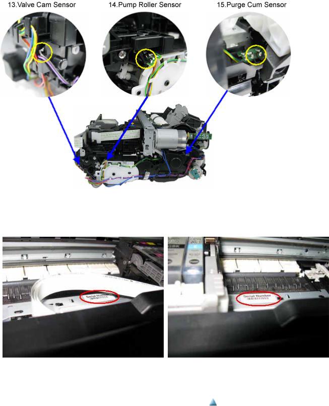
1-5. Serial Number Location
On the inner guide over the upper portion of the spur holder (visible when the scanning unit (cover) is opened)
When the machine power is OFF. |
When the machine power is ON. |
 <1. MAINTENANCE>
6 / 64

MX860 / MX868 |
TABLE OF CONTENTS |
|
|
2. LIST OF ERROR DISPLAY / INDICATION
Errors and warnings are displayed by the following ways:
1.Operator call errors are indicated by the Alarm LED lit in orange, and the error and its solution are displayed on the LCD in text and by icon.
2.Messages during printing from a computer are displayed on the MP driver Status Monitor.
3.Error codes (the latest 10 error codes at the maximum) are printed in the "operator call/service call error record" area in EEPROM information print
Buttons valid when an operator call error occurs:
1.ON button: To turn the machine off and on again.
2.OK button: To clear and recover from an error. In some operator call errors, the error will automatically be cleared when the cause of the error is eliminated, and pressing the OK button may not be necessary.
3.Stop button: To cancel the job at error occurrence, and to clear the error.
2-1. Operator Call Errors (by Alarm LED Lit in Orange)
Error
No paper in the rear tray.
No paper in the cassette.
Error |
|
U |
|
Message on the LCD |
|
Solution |
code |
|
No. |
|
|
||
|
|
|
|
|
||
[1000] |
--- |
|
Rear tray. |
|
Confirm that the rear tray is |
|
|
|
|
|
There is no paper. Load |
|
selected as the paper source. |
|
|
|
|
paper and press [OK]. |
|
Set the paper in the rear tray, |
|
|
|
|
|
|
and press the OK button. |
[1003] |
--- |
|
Cassette. |
|
Confirm that the cassette is |
|
|
|
|
|
There is no paper. Load |
|
selected as the paper source. |
|
|
|
|
paper and press [OK]. |
|
Set the paper in the cassette, |
|
|
|
|
|
|
and press the OK button. |
Parts that are likely to be faulty
-ASF unit
-Pressure roller unit
-Switch system unit
-Paper feed motor
-Pick-up arm unit
-Pressure roller unit
-Switch system unit
-Paper feed motor
Paper jam. |
[1300] |
--- |
The paper is jammed. |
Remove the jammed paper or |
- ASF unit |
|
Paper jam in the |
[1303] |
--- |
Clear the paper and press |
foreign material causing a |
- Pick-up arm unit |
|
[OK]. |
paper jam (paper remainings, |
- Cassette unit |
||||
rear guide. |
|
|
||||
|
|
|
clips, pens, etc.), and press the |
- Pressure roller unit |
||
Paper jam in the |
[1304] |
--- |
|
|||
|
OK button. |
|
||||
under guide. |
|
|
|
|
|
|
Ink may have run |
[1600] |
U041 |
The following ink may |
Replace the applicable ink |
- Ink tank |
|
out. |
|
|
have run out. Replacing |
tank, or press the OK button to |
- Spur unit |
|
|
|
|
the ink tank is |
clear the error without ink tank |
- Logic board |
|
|
|
|
recommended. |
replacement. When the error is |
|
|
|
|
|
|
cleared by pressing the OK |
|
|
|
|
|
|
button, ink may run out during |
|
|
|
|
|
|
printing. |
|
|
Ink tank not |
[1660] |
U043 |
The following ink tank |
Install the applicable ink tank |
- Ink tank |
|
installed. |
|
|
cannot be recognized. |
(s) properly, and confirm that |
- Carriage unit |
|
|
|
|
(Applicable ink tank |
the LED's of all the ink tanks |
- Logic board |
|
|
|
|
icon) |
light red. |
|
|
Print head not |
[1401] |
U051 |
Print head is not |
Install the print head properly. |
- Print head |
|
installed, or not |
|
|
installed. Install the print |
|
- Carriage unit |
|
properly |
|
|
head. |
|
- Logic board |
|
installed. |
|
|
|
|
|
|
Faulty print head |
|
U052 |
The type of print head is |
Re-set the print head. If the |
- Print head |
|
ID. |
|
|
incorrect. Install the |
error is not cleared, the print |
- Logic board |
7 / 64
Print head |
[1403] |
correct print head. |
head may be defective. |
temperature |
|
|
Replace the print head. |
sensor error. |
|
|
|
Faulty EEPROM |
[1405] |
|
|
data of the print |
|
|
|
head. |
|
|
|
Multiple ink |
[1487] |
U071 |
More than one ink tank |
tanks of the same |
|
|
of the following color is |
color installed. |
|
|
installed. |
Ink tank in a |
[1680] |
U072 |
Some ink tanks are not |
wrong position. |
|
|
installed in place. |
Warning: The |
[1700] |
--- |
Contact the support |
ink absorber |
|
|
center or service center |
becomes almost |
|
|
for ink absorber |
full. |
|
|
replacement. Press [OK] |
|
|
|
to continue printing. |
The connected |
[2001] --- Incompatible device |
digital camera or |
detected. Remove the |
digital video |
device. |
camera does not |
|
support Camera Direct Printing.
Replace the wrong ink tank(s) |
- Ink tank |
with the correct one(s). |
- Logic board |
Install the ink tank(s) in the |
- Ink tank |
correct position. |
- Logic board |
Replace the ink absorber, and |
- Absorber kit |
reset its counter. [See 4-5. |
|
Special Notes on Servicing, (5) |
|
Ink absorber counter setting.] |
|
Pressing the OK button will |
|
exit the error, and enable |
|
printing without replacing the |
|
ink absorber. However, when |
|
the ink absorber becomes full, |
|
no further printing can be |
|
performed unless the |
|
applicable ink absorber is |
|
replaced. |
|
Remove the cable between the |
- PictBridge board |
camera and the machine. |
- Logic board |
Automatic duplex [1310] |
--- This paper is not |
printing cannot |
compatible with duplex |
be performed. |
printing. Remove the |
|
paper and press [OK]. |
The remaining |
[1683] U130 (Applicable ink tank |
ink amount |
icon) |
unknown (raw |
The remaining level of |
ink present). |
the ink cannot be |
|
correctly detected. |
The paper length is not |
- Duplex feed roller unit |
supported for duplex printing. |
- PE sensor board |
Press the OK button to eject |
- Logic board |
the paper being used at error |
|
occurrence. |
|
Data which was to be printed |
|
on the back side of paper at |
|
error occurrence is skipped |
|
(not printed). |
|
An ink tank which has once |
- Ink tank |
been empty is installed. |
- Spur unit |
Replace the applicable ink tank |
|
with a new one. Printing with a |
|
once-empty ink tank can |
|
damage the machine. |
|
To continue printing without |
|
replacing the ink tank(s), press |
|
the Stop button for 5 sec. or |
|
longer to disable the function |
|
to detect the remaining ink |
|
amount. After the operation, it |
|
is recorded in the machine |
|
EEPROM that the function to |
|
detect the remaining ink |
|
amount was disabled. |
|
8 / 64

Ink tank not |
[1684] U140 The following ink tank |
recognized. |
cannot be recognized. |
|
(Applicable ink tank |
|
icon) |
Ink tank not |
[1682] |
U150 |
The following ink tank |
recognized. |
|
|
cannot be recognized. |
|
|
|
(Applicable ink tank |
|
|
|
icon) |
No ink (no raw |
[1688] |
U163 |
The ink has run out. |
ink). |
|
|
Replace the ink tank. |
|
|
|
(Applicable ink tank |
|
|
|
icon) |
A non-supported ink tank (an |
- Ink tank |
ink tank that is sold in a |
- Logic board |
different region from where the |
|
machine was purchased) is |
|
installed (the ink tank LED is |
|
turned off). Install the |
|
supported ink tanks. |
|
A hardware error occurred in |
- Ink tank |
an ink tank (the ink tank LED |
- Logic board |
is turned off). Replace the ink |
|
tank(s). |
|
Replace the empty ink tank(s), |
- Ink tank |
and close the scanning unit |
- Spur unit |
(cover). |
- Logic board |
Printing with an empty ink |
|
tank can damage the machine. |
|
To continue printing without |
|
replacing the ink tank(s), press |
|
the Stop button for 5 sec. or |
|
longer to disable the function |
|
to detect the remaining ink |
|
amount. After the operation, it |
|
is recorded in the machine that |
|
the function to detect the |
|
remaining ink amount was |
|
disabled. |
|
Non-supported |
[2002] --- An unsupported USB |
hub. |
hub is connected. |
|
Remove the hub. |
Remove the applicable USB |
- PictBridge board |
hub from the PictBridge (USB) |
- Logic board |
connector. |
|
Document cover |
--- |
--- The feeder cover is open. |
not closed. |
|
Close cover and press |
|
|
[OK]. |
Close the document cover, and |
- DF unit |
press the OK button. |
- DF switch unit |
Paper jam in the |
--- |
--- Document in ADF. Redo |
ADF. |
|
operation after checking |
|
|
document in ADF and |
|
|
pressing [OK]. |
No paper in the |
--- |
--- No document in ADF. |
ADF. |
|
Press [OK] and redo |
|
|
operation after setting |
|
|
document. |
Remove the paper from the |
- DF unit |
ADF, and press the OK button. |
|
Press the OK button to clear |
- DF unit |
the error. |
|
Paper in the ADF |
--- |
--- Document size is too |
is too long. |
|
long. Redo operation |
|
|
after checking document |
|
|
on ADF and pressing |
|
|
[OK]. |
Remove the paper from the |
- DF unit |
ADF, and press the OK button. |
|
Duplex printing |
--- |
--- Document size not |
not available with |
|
suitable for two-sided |
the paper in the |
|
scanning. Press [OK] to |
ADF. |
|
cancel operation and |
|
|
discharge document. |
Remove the paper from the |
- DF unit |
ADF, and press the OK button. |
|
9 / 64

2-2. Service Call Errors (by Cyclic Blinking of Alarm and Power LEDs)
Service call errors are indicated by the number of cycles the Alarm and Power LEDs blink, and the corresponding error code with the message,
"Printer error has occurred. Turn off power then back on again. If problem persists, see the manual." is displayed on the LCD.
Cycles of |
|
|
|
|
|
|
|
|
Solution |
blinking of |
|
Error |
|
Error |
|
Conditions |
|
|
|
Alarm and |
|
|
|
|
|
(Check points and replacement |
|||
|
|
code |
|
|
|
||||
Power |
|
|
|
|
|
|
|
items) |
|
|
|
|
|
|
|
|
|
||
LEDs |
|
|
|
|
|
|
|
|
|
2 times |
|
Carriage error |
|
[5100] An error occurred in the carriage |
(1) |
Smearing or scratches on the carriage |
|||
|
|
|
|
|
|
encoder signal. |
|
slit film; |
|
|
|
|
|
|
|
|
|
|
clean the timing slit film. |
|
|
|
|
|
|
|
(2) |
Foreign material or paper debris that |
|
|
|
|
|
|
|
|
|
obstructs the carriage movement; |
|
|
|
|
|
|
|
|
|
|
remove foreign material. |
|
|
|
|
|
|
|
(3) |
Ink tank conditions; |
|
|
|
|
|
|
|
|
|
|
re-set the ink tanks. |
|
|
|
|
|
|
|
(4) |
Cable connection |
|
|
|
|
|
|
|
|
(5) |
Part replacement: |
|
|
|
|
|
|
|
|
|
|
- Timing slit disk film |
|
|
|
|
|
|
|
|
|
- Carriage unit |
|
|
|
|
|
|
|
|
|
- Logic board |
|
|
|
|
|
|
|
|
|
- Carriage motor |
3 times |
|
Line feed error |
|
[6000] An error occurred in the LF |
(1) |
Smearing or scratches on the LF / EJ slit |
|||
|
|
|
|
|
|
encoder signal. |
|
film; |
|
|
|
|
|
|
|
|
|
|
clean the LF / EJ slit film. |
|
|
|
|
|
|
|
(2) |
Foreign material or paper debris in the |
|
|
|
|
|
|
|
|
|
LF drive; |
|
|
|
|
|
|
|
|
|
|
remove foreign material. |
|
|
|
|
|
|
|
(3) |
Cable connection |
|
|
|
|
|
|
|
|
(4) |
Part replacement: |
|
|
|
|
|
|
|
|
|
|
- LF / EJ slit film |
|
|
|
|
|
|
|
|
|
- LF / EJ timing sensor unit |
|
|
|
|
|
|
|
|
|
- Paper feed roller unit |
|
|
|
|
|
|
|
|
|
- Logic board |
|
|
|
|
|
|
|
|
|
- Paper feed motor |
4 times |
|
Purge cam sensor |
|
[5C00] An error occurred in the purge |
(1) |
Foreign material or paper debris around |
|||
|
|
error |
|
|
|
unit. |
|
the purge drive system unit; |
|
|
|
|
|
|
|
|
|
|
remove foreign material. |
|
|
|
|
|
|
|
(2) |
Cable connection |
|
|
|
|
|
|
|
|
(3) |
Part replacement: |
|
|
|
|
|
|
|
|
|
|
- Purge drive system unit |
|
|
|
|
|
|
|
|
|
- Logic board |
5 times |
|
ASF (cam) sensor |
|
[5700] An error occurred in the ASF |
(1) |
Cable connection |
|||
|
|
error |
|
|
|
cam sensor. |
(2) |
Part replacement: |
|
|
|
|
|
|
|
|
|
|
- ASF unit |
|
|
|
|
|
|
|
|
|
- PE sensor board unit |
|
|
|
|
|
|
|
|
|
- Logic board |
6 times |
|
Internal |
|
[5400] The internal temperature is not |
(1) |
Cable connection |
|||
|
|
temperature error |
|
|
|
normal. |
(2) |
Part replacement: |
|
|
|
|
|
|
|
|
|
|
- Spur unit |
|
|
|
|
|
|
|
|
|
- Logic board |
|
|
|
|
|
|
|
|
|
- Print head |
7 times |
|
Ink absorber full |
|
[5B00, The ink absorber is supposed to |
(1) |
Ink absorber condition |
|||
10 / 64

|
|
5B01] |
be full. |
|
|
|
Message on the LCD: |
|
|
|
Ink absorber full. Service |
|
|
|
required. |
|
|
|
Error codes: |
|
|
|
5B00: Main ink absorber is |
|
|
|
full (overseas). |
|
|
|
5B01: Main ink absorber is |
|
|
|
full (Japan). (In EEPROM |
|
|
|
information print, "5B00" is |
|
|
|
printed instead of "5B01.") |
8 times |
Print head |
[5200] |
The print head temperature |
|
temperature rise |
|
exceeded the specified value. |
|
error |
|
|
9 times |
EEPROM error |
[6800, |
A problem occurred in reading |
|
|
6801] |
from or writing to the EEPROM. |
10 times |
VH monitor error |
[B200] |
The internal temperature |
|
|
|
exceeded the specified value. |
11 times |
Carriage lift |
[5110] |
The carriage did not move up or |
|
mechanism error |
|
down properly. |
12 times |
APP position error [6A80] An error occurred in the APP |
|
motor. |
14 times |
APP sensor error |
[6A90] An error occurred during paper |
|
|
feeding or purging. |
Paper feed cam |
[6B10] An error occurred in the paper |
sensor error |
feed cam sensor during paper |
|
feeding from the cassette, or the |
|
paper absorbing a large amount |
|
of ink jammed in the PF rear |
|
guide. |
16 times |
Pump roller sensor |
[5C20] |
The pump roller position cannot |
|
error |
|
be detected. |
17 times |
Paper eject encoder |
[6010] |
An error occurred in the paper |
|
error |
|
eject encoder signal. |
11 / 64
(2)Part replacement:
-Ink absorber kit
(3)Ink absorber counter value in the EEPROM;
reset the ink absorber counter.
(1)Print head condition
(2)Cable connection
(3)Part replacement:
-Print head
-Logic board
(1)Part replacement:
-Logic board
(1)Part replacement:
-Print head and logic board (Replace them at the same time.)
-Power supply unit
(1)Foreign material or paper debris that obstructs the carriage movement;
remove foreign material.
(2)Part replacement:
-Switch system unit
-Carriage unit
(1)Foreign material or paper debris around the purge drive system unit;
remove foreign material.
(2)Foreign material or paper debris around the ASF unit;
remove foreign material.
(3)Cable connection
(4)Part replacement:
-Purge drive system unit
-Logic board
(1)Jammed paper in the PF rear guide (when a large amount of ink was absorbed in the paper);
remove the jammed paper and foreign material.
(2)Foreign material or paper debris in the cassette or in the PF rear guide;
remove foreign material.
(3)Part replacement:
-PF pick-up unit
-Logic board
(1)Cable connection
(2)Part replacement:
-Purge drive system unit
(1) Smearing or scratches on the LF / EJ slit film;
clean the LF / EJ slit film.

|
|
|
(2) |
Foreign material or paper debris in the |
|
|
|
paper path; |
|
|
|
|
|
remove foreign material. |
|
|
|
(3) |
Cable connection |
|
|
|
(4) |
Part replacement: |
|
|
|
|
- LF / EJ slit film |
|
|
|
|
- LF / EJ timing sensor unit |
|
|
|
|
- Platen unit |
|
|
|
|
- Logic board |
|
|
|
|
- Paper feed motor |
19 times |
Ink tank position |
[6502] None of the ink tank position is |
(1) Ink tank position; |
|
|
sensor error |
detected. |
|
confirm the ink tank position. |
|
|
|
(2) |
Re-set or replacement of ink tanks |
|
|
|
(3) |
Cable connection |
|
|
|
(4) |
Part replacement: |
|
|
|
|
- Spur unit |
|
|
|
|
- Logic board |
20 times |
Other errors |
[6500] An unidentified error or a |
(1) Part replacement: |
|
|
|
network error occurred. |
|
- Logic board |
|
|
|
|
- WLAN board |
21 times |
Drive switch error |
[C000] Drive was not switched properly. |
(1) Foreign material or paper debris in the |
|
|
|
|
drive switch area; |
|
|
|
|
|
remove foreign material. |
|
|
|
(2) |
Ink tank conditions; |
|
|
|
|
confirm that the ink tanks are |
|
|
|
|
seated properly, or re-set the ink |
|
|
|
|
tanks properly. |
|
|
|
(3) |
Part replacement: |
|
|
|
|
- Carriage unit |
|
|
|
|
- Purge drive system unit |
|
|
|
|
- ASF unit |
22 times |
Scanner error |
[5011] An error occurred in the scanner. |
(1) Document pressure sheet conditions |
|
|
|
|
(1) |
Cable connection |
|
|
|
(2) |
Part replacement: |
|
|
|
|
- Document pressure sheet (sponge |
|
|
|
|
sheet) |
|
|
|
|
- Scanner unit |
|
|
|
|
- Logic board |
|
FB motor error |
[5012] An error occurred in the scanner |
(1) Cable connection |
|
|
|
FB motor. |
(2) Part replacement: |
|
|
|
|
|
- Scanner unit |
23 times |
Valve cam sensor |
[6C10] The valve cam sensor was faulty |
(1) Foreign material or paper debris around |
|
|
error |
at power-on or when purging was |
the purge drive system unit; |
|
|
|
attempted. |
|
remove foreign material. |
|
|
|
(2) |
Cable connection |
|
|
|
(3) |
Part replacement: |
|
|
|
|
- Purge drive system unit |
|
|
|
|
- Logic board |
Before replacement of the logic board ass'y, check the ink absorber counter value (by service test print or EEPROM information print). If the counter value is 7% or more, also replace the ink absorber kit when replacing the logic board ass'y. If the counter value is less than 7%, register the current ink absorber counter value to the replaced new logic board instead. [See 4-5. Special Notes on Servicing, (5) Ink absorber counter setting, for details.]
12 / 64

2-3. FAX Errors
For errors other than those listed below, please refer to the "G3 / G4 Facsimile Error Code List (Rev. 2." (HY8-23A0-020 in Japanese, HY8-22A6-020 in English).
(1) User error codes
Error code |
|
TX / RX |
|
Meaning |
|
Solution |
|
|
|
(Parts that are likely to be |
|||
|
|
|
|
|
|
faulty) |
#001 |
|
TX |
|
Document jam |
|
- DF unit |
#003 |
|
TX / RX |
|
Document is too long, or page time-over |
|
- DF unit |
#005 |
|
TX / RX |
|
Initial identification (T0 / T1) time-over |
|
- Check the telephone line type |
|
|
|
|
|
|
settings (rotary pulse / touch tone). |
#009 |
|
RX |
|
Recording paper jam, or no recording paper |
|
- ASF unit |
|
|
|
|
|
|
- Pick-up arm unit |
|
|
|
|
|
|
- Cassette unit |
|
|
|
|
|
|
- Pressure roller unit |
#012 |
|
TX |
|
No recording paper at the receiving machine |
|
|
#017 |
|
TX |
|
Redial time-over, but no DT detected |
|
|
#018 |
|
TX |
|
Auto dialing transmission error, or redial |
|
- Check the telephone line type |
|
|
|
|
time-over |
|
settings (rotary pulse / touch tone). |
#022 |
|
TX |
|
Call failed (no dial registration) |
|
- Register a dial number. |
#037 |
|
RX |
|
Memory overflow at reception of an image |
|
- Delete unnecessary image data from |
|
|
|
|
|
|
the memory. |
#085 |
TX |
No color fax function supported in the |
|
|
receiving machine |
- Send a fax in the B&W mode.
#099 |
TX / RX |
Transmission terminated mid-way by pressing |
|
|
the Stop/Reset button |
#995 |
TX / RX |
During TX (sending): Memory transmission |
|
|
reservation cancelled |
|
|
During RX (receiving): Image data received |
|
|
in the memory cleared |
(2) Service error codes
Error |
|
TX / |
code |
|
RX |
##100 |
|
TX |
Meaning
Re-transmission of the procedure signal has been attempted the specified number of times, but failed.
Solution
(Parts that are likely to be faulty)
- Try a higher transmission level.
##101 |
TX / Sender's modem speed does not match the receiving machine. |
|
RX |
##102 |
TX |
Fallback is not available. |
##103 |
RX |
EOL has not been detected for 5 seconds (or 15 seconds in |
|
|
CBT). |
-Try a higher transmission level.
-Increase the transmission level of the sending machine.
##104 |
TX |
RTN or PIN has been received. |
- Try a higher transmission level. |
##106 |
RX |
The procedure signal has been expected for 6 seconds, but not |
- Increase the transmission level of the |
|
|
received. |
sending machine. |
##107 |
RX |
Fallback is not available at the sending machine. |
- Increase the transmission level of the |
|
|
|
sending machine. |
13 / 64

##109 |
TX |
After DCS transmission, a signal other than DIS, DTC, FTT, |
|
|
CFR, or CRP has been received, and re-transmission of the |
|
|
procedure signal has been attempted the specified number of |
|
|
times but failed. |
##111 |
TX / |
Memory error |
|
RX |
|
##114 |
RX |
RTN has been received. |
##200 |
RX |
A carrier has not been detected for 5 seconds during image |
|
|
reception. |
##201 |
TX / |
DCN has been received in a method other than the binary |
|
RX |
procedure. |
##204 |
TX |
DTC has been received even when there is no sending data. |
##220 |
TX / |
System error (main program hang-up) |
|
RX |
|
##224 |
TX / |
An error has occurred in the procedure signal in G3 |
|
RX |
transmission. |
##226 |
TX / |
The stack pointer has shifted from the RAM area. |
|
RX |
|
##229 |
RX |
The recording area has been locked for 1 minute. |
##232 |
TX |
The encoder control unit has malfunctioned. |
##237 |
RX |
The decoder control unit has malfunctioned. |
##238 |
RX |
The print control unit has malfunctioned. |
##261 |
TX / |
A system error has occurred between the modem and the |
|
RX |
system control board. |
##280 |
TX |
Re-transmission of the procedure signal has been attempted |
|
|
the specified number of times, but failed. |
##281 |
TX |
Re-transmission of the procedure signal has been attempted |
|
|
the specified number of times, but failed. |
##282 |
TX |
Re-transmission of the procedure signal has been attempted |
|
|
the specified number of times, but failed. |
##283 |
TX |
Re-transmission of the procedure signal has been attempted |
|
|
the specified number of times, but failed. |
##284 |
TX |
After TCF transmission, DCN has been received. |
##285 |
TX |
After EOP transmission, DCN has been received. |
##286 |
TX |
After EOM transmission, DCN has been received. |
##287 |
TX |
After MPS transmission, DCN has been received. |
##288 |
TX |
After EOP transmission, a signal other than PIN, PIP, MCF, |
|
|
RTP, RTN has been received. |
##289 |
TX |
After EOM transmission, a signal other than PIN, PIP, MCF, |
-Eliminate all the data, and register them again.
-Increase the transmission level of the sending machine.
-Increase the transmission level of the sending machine.
-Set the other machine ready for reception.
-Turn the machine off, and turn it on again
-Modular board
-Logic board
-Turn the machine off, and turn it on again.
-After the area is unlocked, print the recorded image.
-Modular board
-Logic board
-Modular board
-Logic board
-Modular board
-Logic board
-Modular board
-Logic board
-Try a higher transmission level.
-Try a higher transmission level.
-Try a higher transmission level.
-Try a higher transmission level.
-Set the receiving machine ready for reception.
-Re-send the fax.
-Re-send the fax.
-Re-send the fax.
14 / 64

|
|
RTP, RTN has been received. |
##290 |
TX |
After MPS transmission, a signal other than PIN, PIP, MCF, |
|
|
RTP, RTN has been received. |
##670 |
TX |
In V.8 late start, the DIS V.8 ability from the receiving |
|
|
machine was detected, and CI was sent in response; however, |
|
|
the procedure failed, causing T1 time-over. |
-In bit 0 of the service data #1 SSSW SW28, prohibit the V.8 / V.34 procedure of the sending machine.
##671 |
RX |
In V.8 call reception, the procedure fails to proceed to phase 2 |
|
|
after CM detection, causing T1 time-over. |
-In bit 0 of the service data #1 SSSW SW28, prohibit the V.8 / V.34 procedure of the sending machine.
##672 |
TX |
In V.34 transmission, the procedure fails to proceed from |
|
|
phase 2 to phase 3 or later, causing T1 time-over |
-In bit 0 of the service data #1 SSSW SW28, prohibit the V.8 / V.34 procedure of the sending machine.
##673 |
RX |
In V.34 reception, the procedure fails to proceed from phase 2 |
|
|
to phase 3 or later, causing T1 time-over |
-In bit 0 of the service data #1 SSSW SW28, prohibit the V.8 / V.34 procedure of the sending machine.
##674 |
TX |
In V.34 transmission, the procedure fails to proceed from |
|
|
phase 3 or 4 to the control channel or later, causing T1 time- |
|
|
over |
-In bit 0 of the service data #1 SSSW SW28, prohibit the V.8 / V.34 procedure of the sending machine.
##675 |
RX |
In V.34 reception, the procedure fails to proceed from phase 3 |
|
|
or 4 to the control channel or further, causing T1 time-over |
-In bit 0 of the service data #1 SSSW SW28, prohibit the V.8 / V.34 procedure of the sending machine.
##750 TX After transmitting PPS-NULL in ECM transmission, no - Try a higher transmission level. significant signal has been received, and re-transmission of
the procedure signal has been attempted the number of specified times but failed.
##752 |
TX |
After transmitting PPS-NULL in ECM transmission, DCN |
|
|
has been received. |
##753 |
TX |
After transmitting PPS-NULL in ECM transmission, re- |
|
|
transmission of the procedure signal has been attempted the |
|
|
number of specified times but failed, or T5 time-over (60 |
|
|
sec.) has occurred. |
##754 |
TX |
After transmitting PPS-NULL in ECM transmission, re- |
|
|
transmission of the procedure signal has been attempted the |
|
|
number of specified times but failed. |
-Try a higher transmission level.
-Increase the period of time of the T5 time-over.
-Try a higher transmission level.
##755 TX After transmitting PPS-MPS in ECM transmission, no - Try a higher transmission level. significant signal has been received, and re-transmission of
the procedure signal has been attempted the number of specified times but failed.
##757 |
TX |
After transmitting PPS-MPS in ECM transmission, DCN has |
|
|
been received. |
##758 |
TX |
After transmitting PPS-MPS in ECM transmission, re- |
|
|
transmission of the procedure signal has been attempted the |
|
|
number of specified times but failed, or T5 time-over (60 |
|
|
sec.) has occurred. |
##759 |
TX |
After transmitting PPS-MPS in ECM transmission, re- |
|
|
transmission of the procedure signal has been attempted the |
|
|
number of specified times but failed. |
##760 |
TX |
After transmitting PPS-EOM in ECM transmission, no |
|
|
significant signal has been received, and re-transmission of |
|
|
the procedure signal has been attempted the number of |
|
|
specified times but failed. |
|
|
15 / 64 |
-Try a higher transmission level.
-Increase the period of time of the T5 time-over.
-Try a higher transmission level.
-Try a higher transmission level.

##762 |
TX |
After transmitting PPS-EOM in ECM transmission, DCN has |
|
|
been received. |
##763 |
TX |
After transmitting PPS-EOM in ECM transmission, re- |
|
|
transmission of the procedure signal has been attempted the |
number of specified times but failed, or T5 time-over (60 sec.) has occurred.
-Try a higher transmission level.
-Increase the period of time of the T5 time-over.
##764 |
TX |
After transmitting PPS-EOM in ECM transmission, re- |
|
|
transmission of the procedure signal has been attempted the |
|
|
number of specified times but failed. |
##765 |
TX |
After transmitting PPS-EOP in ECM transmission, no |
|
|
significant signal has been received, and re-transmission of |
|
|
the procedure signal has been attempted the number of |
|
|
specified times but failed. |
##767 |
TX |
After transmitting PPS-EOP in ECM transmission, DCN has |
|
|
been received. |
##768 |
TX |
After transmitting PPS-EOP in ECM transmission, re- |
|
|
transmission of the procedure signal has been attempted the |
|
|
number of specified times but failed, or T5 time-over (60 |
|
|
sec.) has occurred. |
##769 |
TX |
After transmitting PPS-EOP in ECM transmission, re- |
|
|
transmission of the procedure signal has been attempted the |
|
|
number of specified times but failed. |
##770 |
TX |
After transmitting EOR-NULL in ECM transmission, no |
|
|
significant signal has been received, and re-transmission of |
the procedure signal has been attempted the number of specified times but failed.
-Try a higher transmission level.
-Increase the transmission level of the receiving machine.
-Try a higher transmission level.
-Increase the transmission level of the receiving machine.
-Try a higher transmission level.
-Increase the period of time of the T5 time-over.
-Try a higher transmission level.
-Increase the transmission level of the receiving machine.
-Try a higher transmission level.
-Increase the transmission level of the receiving machine.
##772 |
TX |
After transmitting EOR-NULL in ECM transmission, DCN |
|
|
has been received. |
##773 |
TX |
After transmitting EOR-NULL in ECM transmission, re- |
|
|
transmission of the procedure signal has been attempted the |
number of specified times but failed, or T5 time-over (60 sec.) has occurred.
-Try a higher transmission level.
-Increase the period of time of the T5 time-over.
##774 |
TX |
After transmitting EOR-NULL in ECM transmission, ERR |
|
|
has been received. |
##775 |
TX |
After transmitting EOR-MPS in ECM transmission, no |
|
|
significant signal has been received, and re-transmission of |
the procedure signal has been attempted the number of specified times but failed.
-Try a higher transmission level.
-Try a higher transmission level.
##777 |
TX |
After transmitting EOR-MPS in ECM transmission, DCN has |
|
|
been received. |
##778 |
TX |
After transmitting EOR-MPS in ECM transmission, re- |
|
|
transmission of the procedure signal has been attempted the |
number of specified times but failed, or T5 time-over (60 sec.) has occurred.
-Try a higher transmission level.
-Increase the period of time of the T5 time-over.
##779 |
TX |
After transmitting EOR-MPS in ECM transmission, ERR has |
|
|
been received. |
##780 |
TX |
After transmitting EOR-EOM in ECM transmission, no |
|
|
significant signal has been received, and re-transmission of |
the procedure signal has been attempted the number of specified times but failed.
-Try a higher transmission level.
-Increase the transmission level of the receiving machine.
##782 |
TX |
After transmitting EOR-EOM in ECM transmission, DCN |
- Increase the transmission level of the |
16 / 64

has been received. |
receiving machine. |
##783 |
TX |
After transmitting EOR-EOM in ECM transmission, re- |
|
|
transmission of the procedure signal has been attempted the |
number of specified times but failed, or T5 time-over (60 sec.) has occurred.
-Increase the period of time of the T5 time-over.
##784 |
TX |
After transmitting EOR-EOM in ECM transmission, ERR has |
|
|
been received. |
##785 |
TX |
After transmitting EOR-EOP in ECM transmission, no |
|
|
significant signal has been received, and re-transmission of |
|
|
the procedure signal has been attempted the number of |
|
|
specified times but failed. |
##787 |
TX |
After transmitting EOR-EOP in ECM transmission, DCN has |
|
|
been received. |
##788 |
TX |
After transmitting EOR-EOP in ECM transmission, re- |
|
|
transmission of the procedure signal has been attempted the |
|
|
number of specified times but failed, or T5 time-over (60 |
|
|
sec.) has occurred. |
-Try a higher transmission level.
-Try a higher transmission level.
-Increase the transmission level of the receiving machine.
-Try a higher transmission level.
-Increase the period of time of the T5 time-over.
##789 |
TX |
After transmitting EOR-EOP in ECM transmission, ERR has |
|
|
been received. |
##790 |
RX |
After receiving EOR-EOP in ECM reception, ERR has been |
|
|
transmitted. |
##791 |
TX / |
During the ECM mode procedure, a signal other than a |
|
RX |
significant one has been received. |
##792 |
RX |
In ECM reception, PPS-NULL between partial pages has not |
|
|
been detected. |
##793 |
RX |
During high-speed signal reception in ECM, no effective |
|
|
frame has been detected, and a time-over has occurred. |
-Try a higher transmission level.
-Increase the transmission level of the sending machine.
-Increase the transmission level of the sending machine.
-Try a higher transmission level.
-Increase the transmission level of the sending machine.
17 / 64
2-4. Troubleshooting by Symptom
|
|
Symptom |
Faulty operation |
|
The power does not turn on. |
|
|
The power turns off immediately |
|
|
after power-on. |
A strange noise occurs.
The LCD does not display properly. A portion of the LCD is not displayed.
The display flickers.
Paper feed problems (multi-feeding, skewed feeding, no feeding).
Faulty scanning (no scanning, strange noise).
Unsatisfactory print quality No printing, or no color ejected. Faint printing, or white lines on printouts.
Uneven printing. Improper color hue.
Solution
(1)Confirm connection of the power supply unit:
-Harness and connector conditions
(2)Replace the following item(s):
-Logic board
-Power supply unit
-Panel board
(1)Examine and remove any foreign material or paper debris.
(2)Replace the following item(s):
-The part generating the strange noise
-Logic board
(1)Confirm cable connection (LCD FFC and panel harness):
-Harness and connector conditions
-No cable breakage, etc.
(2)Replace the following item(s):
-LCD FFC
-LCD viewer unit
-Panel board
-Logic board
(1)Examine and remove any foreign material or paper debris.
(2)Confirm the PF rear cover and the cassette conditions.
(3)Confirm cable connection.
(4)Replace the following item(s):
-ASF unit (for paper feeding error from the rear tray)
-PF pick-up unit (for paper feeding error from the cassette)
-DF unit (for document scanning error)
-PE sensor board
-Pressure roller unit
-Cassette unit
(1)Confirm cable connection (scanner motor cable and CIS FFC):
-Harness and connector conditions
-No cable breakage, etc.
(2)Replace the following item(s):
-Scanner unit
-Logic board
(1)Confirm the ink tank conditions:
-Confirmation of the air-through of an ink tank
-Re-setting of an ink tank
(2)Remove foreign material from the purge unit caps, if any.
(3)Perform cleaning or deep cleaning of the print head.
(4)Perform print head alignment.
(5)Replace the following item(s):
-Print head*1, and ink tanks
-Logic board
-Purge drive system unit
18 / 64

Paper gets smeared. |
(1) |
Clean the inside of the machine. |
|
(2) |
Perform bottom plate cleaning. |
|
(3) |
Perform paper feed roller cleaning. |
The back side of paper gets smeared.
Graphic or text is enlarged on printouts in the carriage movement direction.
(1)Clean the inside of the machine.
(2)Perform bottom plate cleaning.
(3)Examine the platen ink absorber.
(4)Examine the paper eject roller.
(5)Replace the following item(s):
-The part in the paper path causing the smearing
(1)Confirm that the carriage slit film is free from smearing or scratches:
-Cleaning of the timing slit film.
(2)Replace the following item(s):
-Timing slit film
-Carriage unit
-Logic board
-Scanner unit (for copying)
Graphic or text is enlarged on printouts in the paper feed direction.
(1)Confirm that the LF / EJ slit film is free from smearing or scratches:
-Cleaning of the LF / EJ slit film..
(2)Replace the following item(s):
-LF / EJ slit film
-LF / EJ timing sensor unit
-Platen unit
-Logic board
-Scanner unit (for copying)
Faulty scanning |
No scanning. |
|
Streaks or smears on the scanned |
|
image. |
(1)Replace the following item(s):
-Scanner unit
-Logic board
(1)Clean the platen glass and the document pressure sheet.
(2)Confirm the position of the document pressure sheet.
(3)Replace the following item(s):
-Scanner unit
-Document pressure sheet
-Logic board
Network connection problem No printing. |
(1) |
Examine if printing is performed properly via USB |
|
connection. |
|
|
(2) |
Confirm the network settings. |
|
(3) |
Replace the following item(s): |
- Logic board (for wired / wireless LAN) - WLAN board (for wireless LAN)
FAX problem |
No FAX sending or reception. |
(1)Confirm the FAX settings.
(2)Replace the following item(s):
-Modular board
-Logic board
*1: Replace the print head only after the print head deep cleaning is performed 2 times, and when the problem persists.
 <2. LIST OF ERROR DISPLAY / INDICATION>
19 / 64

MX860 / MX868 |
TABLE OF CONTENTS |
|
|
3. REPAIR
3-1. Major Replacement Parts (and Notes on Disassembling / Reassembling)
Service
part
Logic board ass'y
Absorber kit
Carriage unit
Est. time |
|
|
Recommended removal |
|
|
|
|
|
required |
|
|
procedure / Notes on |
|
Adjustment / settings |
|
Operation check |
|
(min.) |
|
|
replacement*1 |
|
|
|
|
|
15 |
(1) |
Right cover |
|
After replacement: |
|
- EEPROM information |
||
|
(2) |
Logic board |
1. |
Initialize the EEPROM. |
|
|||
|
|
|
|
2. |
Set the ink absorber |
|
- Service test print |
|
|
|
- Before removal of the logic board |
|
|
counter value. |
|
- Printing via USB |
|
|
|
ass'y, remove the power cord, and |
3. |
Set the destination in the |
|
connection |
||
|
|
allow for approx. 1 minute (for |
|
|
EEPROM. |
|
- Copying |
|
|
|
discharge of capacitor's accumulated |
4. |
Correct the CD / DVD |
|
- Direct printing from a |
||
|
|
charges), to prevent damages to the |
|
|
and automatic print head |
|
digital camera |
|
|
|
logic board ass'y. |
|
|
alignment sensors. |
|
(PictBridge) |
|
|
|
- Before replacement, check the ink |
5. |
Check the ink system |
|
|
||
|
|
absorber counter value (by service |
|
|
function. |
|
|
|
|
|
test print or EEPROM information |
6. |
Perform LF / Eject |
|
|
||
|
|
print). |
|
|
correction. |
|
|
|
|
|
|
|
7. |
Perform button and LCD |
|
|
|
|
|
|
|
|
|
test. |
|
|
|
|
|
|
|
|
Perform 1 to 7 in the |
|
|
|
|
|
|
|
|
service mode. |
|
|
|
|
|
|
|
|
[See 4-2. Service Mode, |
|
|
|
|
|
|
|
|
for details.] |
|
|
|
|
|
|
8. |
Perform print head |
|
|
|
|
|
|
|
|
|
alignment and LCD |
|
|
|
|
|
|
|
|
language setting in the |
|
|
|
|
|
|
|
|
user mode. |
|
|
15 |
(1) |
Right cover |
|
After replacement: |
|
- Ink absorber counter |
||
|
(2) |
Left cover |
1. |
Reset the ink absorber |
|
value print (After the ink |
||
|
(3) |
Document cover / Scanning unit |
|
|
counter. |
|
absorber counter is reset, |
|
|
|
(cover) |
|
|
[See 4-2. Service Mode, |
|
the counter value is |
|
|
(4) |
Main case |
|
|
for details.] |
|
printed automatically.) |
|
|
(5) |
Printer unit |
|
|
|
|
|
|
|
(6) |
Absorber kit |
|
|
|
|
|
|
20 |
(1) |
Right cover |
|
At replacement: |
|
- Service test print |
||
|
(2) |
Left cover |
1. |
Before removal of the |
|
(Confirm ink system |
||
|
(3) |
Document cover / Scanning unit |
|
|
carriage rail, mark the |
|
function.) |
|
|
|
(cover) |
|
|
carriage rail position. |
|
|
|
|
(4) |
Main case |
|
|
[See 4-5. Special Notes |
|
|
|
|
(5) |
Printer unit |
|
|
on Servicing, (3) |
|
|
|
|
(6) |
Logic board / PE sensor |
|
|
Carriage unit |
|
|
|
|
(7) |
ASF unit |
|
|
replacement, for details.] |
|
|
|
|
(8) |
Carriage unit |
2. |
Apply grease to the |
|
|
||
|
|
|
|
|
|
sliding portions of the |
|
|
|
|
|
|
|
|
carriage rail. |
|
|
|
|
|
|
|
|
[See 4-4. Grease |
|
|
|
|
|
|
|
|
Application, for details.] |
|
|
|
|
|
|
3. |
Check the ink system |
|
|
|
|
|
|
|
|
|
function. |
|
|
|
|
|
|
|
|
[See 4-2. Service Mode, |
|
|
|
|
|
|
|
|
for details.] |
|
|
|
|
|
|
4. |
Perform print head |
|
|
|
20 / 64

|
|
|
|
alignment in the user mode. |
|
Switch |
30 |
(1) Right cover |
At replacement: |
- EEPROM information |
|
system unit |
|
(2) Left cover |
1. Adjust the paper feed |
||
|
|
(3) |
Document cover / Scanning unit |
motor. |
- Service test print |
|
|
(cover) |
[See 4-5. Special Notes |
|
|
|
|
(4) |
Main case |
on Servicing, (2) Paper |
|
|
|
(5) |
Printer unit |
feed motor adjustment, |
|
|
|
(6) |
Logic |
for details.] |
|
|
|
board / PE sensor |
|
|
|
|
|
(7) |
ASF unit |
|
|
Paper feed |
|
(8) Carriage unit |
|
|
|
motor |
|
(9) Spur unit / Platen unit |
|
|
|
|
|
(10) Switch system / Paper feed motor |
|
|
|
|
|
- The screws securing the paper feed |
|
|
|
|
|
motor are allowed to be loosened |
|
|
|
|
|
only for paper feed motor |
|
|
|
|
|
replacement. (DO NOT loosen them |
|
|
|
|
|
in any other cases.) |
|
|
|
Platen unit |
30 |
(1) Right cover |
After replacement: |
- EEPROM information |
|
|
|
(2) |
Left cover |
1. Perform LF / Eject |
|
|
|
(3) |
Document cover / Scanning unit |
correction in the service |
- Service test print |
|
|
(cover) |
mode. |
|
|
|
|
(4) |
Main case |
[See 4-2. Service Mode, |
|
|
|
(5) |
Printer unit |
for details.] |
|
|
|
(6) |
Logic board |
|
|
|
|
(7) |
Carriage unit |
|
|
|
|
(8) |
Spur unit |
|
|
|
|
(9) |
Platen unit |
|
|
Spur unit |
30 |
(1) Right cover |
After replacement: |
- EEPROM information |
|
|
|
(2) |
Left cover |
1. Check the ink system |
|
|
|
(3) |
Document cover / Scanning unit |
function. |
- Service test print |
|
|
(cover) |
2. Perform LF / Eject |
|
|
|
|
(4) |
Main case |
correction in the service |
|
|
|
(5) |
Printer unit |
mode. |
|
|
|
(6) |
Logic board |
[See 4-2. Service Mode, |
|
|
|
(7) |
Carriage unit |
for details.] |
|
|
|
(8) |
Spur unit |
|
|
|
|
(9) |
Platen unit |
|
|
- DO NOT contact the spur edges.
Purge drive |
30 |
(1) Right cover |
After replacement: |
- Service test print |
|
system unit |
|
(2) |
Left cover |
1. Confirm the purging |
|
|
|
(3) |
Document cover / Scanning unit |
operation and the |
|
|
|
(cover) |
machine operation. |
|
|
|
|
(4) |
Main case |
[See 4-6. Verification |
|
|
|
(5) |
Printer unit |
After Repair for details.] |
|
(6)Logic board / PE sensor
(7)ASF unit
(8)Carriage unit
(9)Spur unit / Platen unit
(10)Purge drive system unit
Carriage rail |
30 |
(1) |
Right cover |
At replacement: |
- Service test print |
and main |
|
(2) |
Left cover |
1. Apply grease to the |
|
chassis |
|
(3) Document cover / Scanning unit |
sliding portions. |
|
|
|
|
(cover) |
[See 4-4. Grease |
|
|
21 / 64

Idler pulley parallel pin
APP code wheel gear shaft
Document pressure sheet
Document bottom cover
Scanner unit
LCD ass'y
Timing slit strip film
Timing slit disk feed film
Print head
Wireless LAN board ass'y
30 (4) Main case
(5) Printer unit
30(6) Logic board / PE sensor
(7)ASF unit
(8)Carriage unit
(9)Spur unit / Platen unit
(10)Purge drive system unit
10(1) Right cover
(2)Left cover
(3)Scanner unit
10
10
10(1) Panel cover
(2)Operation panel
(3)LCD ass'y
-Be cautious not to scratch or damage the LCD cable.
Application, for details.]
At replacement: |
- Service test print |
1.Confirm the document pressure sheet position. [See 4-5. Special Notes on Servicing, (4)
Document pressure sheet replacement, for details.]
At replacement: |
- Service test print |
1.Perform button and LCD test.
[See 4-2. Service Mode, for details.]
15 |
(1) |
Right cover |
After replacement: |
- EEPROM information |
|
|
(2) |
Left cover |
1. |
Perform print head |
|
|
(3) |
Document cover / Scanning unit |
|
alignment in the user |
- Service test print |
|
(cover) |
|
mode. |
|
|
|
(4) |
Main case |
2. |
Perform LF / Eject |
|
15 |
- Upon contact with the film, wipe the |
|
correction in the service |
|
|
|
|
mode. |
|
||
|
film with ethanol. |
|
[See 4-2. Service Mode, |
|
|
|
- Confirm no grease is on the film. |
|
for details.] |
|
|
|
(Wipe off any grease thoroughly |
|
|
|
|
|
with ethanol.) |
|
|
|
|
|
- Do not bend the film |
|
|
|
|
1 |
|
|
After replacement: |
- Service test print |
|
|
|
|
1. |
Perform print head |
|
|
|
|
|
alignment in the user |
|
|
|
|
|
mode. |
|
|
|
|
2. |
Perform nozzle check |
|
|
|
|
|
pattern printing in the |
|
|
|
|
|
user mode. |
|
15 |
(1) |
Right cover |
After replacement: |
- EEPROM information |
|
|
(2) |
Left cover |
1. |
Reset the LAN settings |
|
|
(3) |
Document cover / Scanning unit |
|
in the user mode. |
- Service test print |
|
(cover) |
2. |
Print the EEPROM |
|
|
|
(4) |
Main case |
|
information in the |
|
|
(5) |
Wireless LAN board ass'y |
|
service mode to confirm |
|
|
|
|
|
that the WL LAN MAC |
|
|
|
|
|
address is properly |
|
updated.
[See 4-2. Service Mode, for details.]
22 / 64

*1: General notes:
-Make sure that the flexible cables and wires in the harness are in the proper position and connected correctly. See 3-
2.Part Replacement Procedures or the Parts Catalog for details.
-Do not drop the ferrite core, which may cause damage.
-Protect electrical parts from damage due to static electricity.
-Before removing a unit, after removing the power cord, allow the machine to sit for approx. 1 minute (for capacitor discharging to protect the logic board ass'y from damages).
-Do not touch the timing slit strip film, timing slit disk feed film, and timing slit disk eject film. No grease or abrasion is allowed.
-Protect the units from soiled with ink.
-Protect the housing from scratches.
-Exercise caution with the screws, as follows:
i.The screws of the paper feed motor may be loosened only at replacement of the paper feed motor unit (DO NOT loosen them in other cases).
ii.Before loosening the 3 screws that fix the carriage rail to the main chassis, mark the screw positions so
that the carriage rail will be re-attached to the main chassis in its original position. [See 4-5. Special Notes on Servicing, (3) Carriage unit replacement, for details.]
 <3-1. Major Replacement Parts>
23 / 64

MX860 / MX868 --- 3. REPAIR |
TABLE OF CONTENTS |
|
|
3-2. Part Replacement Procedures (Click on the image to enlarge it.)
Be sure to protect the machine from static electricity in repair servicing, especially for the LCD, operation panel board, scanner unit, logic board, card board, WLAN board, modular board, and PE sensor board.
(1)External housing, scanner unit, and document cover removal
1)Remove the cassette and the rear guide unit. (no screws)
2) Remove the AC adapter. (1 screw)
<Pull out the AC adapter from the bottom of the bottom case.> <The core fits to the AC adapter rib.>
See "4-5. Special Notes on Servicing, (6) Power supply unit and modular board replacement."
24 / 64

3) Remove the side cover R. (2 screws)
<The scanner unit hinges are fitted in the right and left side covers.>
25 / 64

4) Remove the scanner cable, LCD cable, document feeder harness, panel ground harness, and core. (1 screw) <The core fits to the main case rib.>
5) Remove the side cover L, disengage the scanner support, then separate the scanner from the printer. (4 screws)
26 / 64
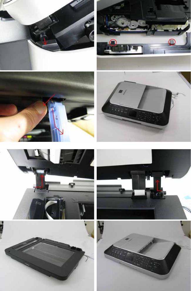
6) Separate the scanner from the document feeder. (no screws)
27 / 64
 Loading...