


 Loading...
PIXMA MP600 / MP600R
SERVICE
MANUAL
Canon
Copyright 2006, Canon U.S.A. This technical publication is the proprietary and confidential information of Canon U.S.A. which shall be retained for reference purposes by Authorized Service Facilities of Canon U.S.A. Its unauthorized use is prohibited.

PIXMA MP600
I. MANUAL OUTLINE
This manual consists of the following three parts to provide information necessary to service the PIXMA MP600:
Part 1: Maintenance
Information on maintenance and troubleshooting of the PIXMA MP600
Part 2: Technical Reference
New technology and technical information such as FAQ's (Frequently Asked Questions) of the PIXMA MP600
Part 3: Appendix
Block diagrams and pin layouts of the PIXMA MP600
Reference
This manual does not provide sufficient information for disassembly and reassembly procedures. Refer to the graphics in the separate Parts Catalog.
 <I. MANUAL OUTLINE>

PIXMA MP600
II. TABLE OF CONTENTS
Part 1: MAINTENANCE
1. MAINTENANCE
1-1. Adjustment, Periodic Maintenance, Periodic Replacement Parts, and Replacement Consumables by Service Engineer
1-2. Customer Maintenance
1-3. Product Life
1-4. Special Tools
1-5. Serial Number Location
2.LIST OF ERROR DISPLAY / INDICATION 2-1. Operator Call Errors
2-2. Service Call Errors
2-3. Other Error Messages
2-4. Warnings
2-5. Troubleshooting by Symptom
3.REPAIR
3-1. Notes on Service Part Replacement
3-2. Special Notes on Repair Servicing
3-3. Adjustment / Settings
(1)Paper feed motor adjustment
(2)Grease application
(3)Ink absorber counter setting
(4)User mode
(5)Service mode
A:Service test print, EEPROM initialization, Ink absorber counter resetting
B:Destination settings
C:LF / Eject correction
D:Left margin correction
E:Ink absorber counter setting
F:Button and LCD test
3-4. Verification Items
(1)Service test print
(2)EEPROM information print
4.MACHINE TRANSPORTATION

Part 2: TECHNICAL REFERENCE
1.NEW TECHNOLOGIES
2.CLEANING MODE AND AMOUNT OF INK PURGED
3.PRINT MODE
4.FAQ (Problems Specific to the MP600 and Corrective Actions)
Part 3: APPENDIX
1.BLOCK DIAGRAM
2.CONNECTOR LOCATION AND PIN LAYOUT 2-1. Logic Board
2-2. Carriage Board (Print Head Connector)
2-3. Print Beam / PictBridge Board
2-4. Card Slot Board (Card Slot Unit)
2-5. Operation Panel Board
3.PIXMA MP600 SPECIFICATIONS
4.PRINT MEDIA SPECIFICATIONS
 <II. TABLE OF CONTENTS>

PIXMA MP600 |
TABLE OF CONTENTS |
|
|
Part 1
MAINTENANCE

Part 1: MAINTENANCE |
TABLE OF CONTENTS |
|
|
1. MAINTENANCE
1-1. Adjustment, Periodic Maintenance, Periodic Replacement Parts, and Replacement Consumables by Service Engineer
(1) Adjustment
|
|
Adjustment |
|
Timing |
|
Purpose |
|
Tool |
|
Approx. |
|
|
|
|
|
|
time |
||||
|
|
|
|
|
|
|
|
|
|
|
|
|
Destination settings |
|
- At logic board replacement |
|
To set destination. |
|
None. |
|
1 min. |
|
|
(EEPROM settings) |
|
|
|
|
|
Perform in the |
|
|
|
|
|
|
|
|
|
|
service mode. |
|
|
|
|
EEPROM |
|
- At logic board replacement |
|
To initialize settings |
|
None. |
|
1 min. |
|
|
initialization |
|
|
|
|
|
Perform in the |
|
|
|
|
|
|
|
|
|
|
service mode. |
|
|
Ink absorber counter |
- At logic board replacement |
resetting |
- At ink absorber replacement |
(EEPROM settings) |
|
Ink absorber counter |
- At logic board replacement |
value setting |
|
(EEPROM settings) |
|
Paper feed motor |
- At paper feed motor |
position adjustment |
replacement |
Print head alignment |
- At print head replacement |
|
|
- At logic board replacement |
|
|
- When print quality is not |
|
|
satisfying |
|
LF / Eject correction |
- At logic board replacement |
|
|
- At feed roller ass'y |
|
New |
replacement |
|
- At platen unit replacement |
||
|
To reset the ink absorber counter.
To set the ink amount data in the ink absorber to the ink absorber counter.
None. |
1 min. |
Perform in the |
|
service mode. |
|
None. |
1 min. |
Perform in the |
|
service mode. |
|
To adjust the belt tension. |
None. |
2 min. |
(Position the paper feed motor so that the |
|
|
belt is stretched tight.) |
|
|
To secure the dot placement accuracy. |
- Computer |
Manual: |
|
(MP driver) |
5 min. |
|
- Machine |
Auto: 4 |
|
button |
|
|
|
min. |
LF correction: |
None. |
5 min. |
To correct line feeding |
Perform in the |
|
Eject correction: |
service mode. |
|
To adjust eject rollers and maintain the |
|
|
paper eject accuracy using the eject |
|
|
encoder for the trailing edge of paper |
|
|
Grease application |
- At carriage unit replacement |
|
- At PR shaft ass'y replacement |
|
- At CL base or CL gear |
|
replacement |
Ink system function |
- At logic board replacement |
check |
- At platen unit replacement |
|
- At carriage unit replacement |
LCD language |
- At logic board replacement |
settings |
|
To maintain sliding properties of the following items:
-Carriage shaft
-Lift cam bushing
-Machine sliding portions (gears)
To maintain detection functionality for presence of the ink tanks and each ink tank position.
To set the language to be displayed on the LCD.
1-1
FLOIL KG- |
1 min. |
107A |
|
None. |
1 min. |
Perform in the |
|
service mode. |
|
None. |
1 min. |
Perform in the |
|
user mode. |
|

Document pressure |
- At document pressure sheet |
To adjust the pressure sheet to fit in place to None. |
1 min. |
sheet position |
replacement |
the four corners of the platen glass when the |
|
adjustment |
|
cover is closed. |
|
Caution: DO NOT loosen the red screws at both ends of the carriage shaft, securing the print head position, as they are not readjustable.
The red screws securing the paper feed motor may be loosened only at replacement of the paper feed motor unit..
(2) Periodic maintenance
No periodic maintenance is necessary.
(3) Periodic replacement parts
There are no parts in this machine that require periodic replacement by a service engineer.
(4) Replacement consumables
There are no consumables that require replacement by a service engineer.
1-2. Customer Maintenance
Adjustment |
|
Timing |
|
Purpose |
|
Tool |
|
|
|
|
|
|
|
Print head |
|
At print head replacement |
|
To ensure |
|
- Machine buttonsComputer |
alignment |
|
|
|
accurate dot |
|
(automatic alignment via MP |
|
|
|
|
placement. |
|
driver) |
Print head cleaning |
|
When print quality is not satisfying. |
|
To improve |
|
- Machine buttonsComputer |
|
|
|
|
nozzle conditions. |
|
(MP driver) |
Print head deep |
|
When print quality is not satisfying, and not |
|
To improve |
|
- Machine buttonsComputer |
cleaning |
|
improved by print head cleaning. |
|
nozzle conditions. |
|
(MP driver) |
Ink tank |
|
When an ink tank becomes empty. ("No ink |
|
― |
|
― |
replacement |
|
error" displayed on the monitor or on the |
|
|
|
|
|
|
machine LCD, or short flashing of an ink tank |
|
|
|
|
|
|
LED) |
|
|
|
|
Approx.
time
4 min.
1min.
2min.
2min.
Paper feed roller |
When paper does not feed properly. |
To clean the paper - Machine buttons |
2 min. |
cleaning |
|
feed rollers. |
|
Bottom plate |
When the back side of the paper is smeared. |
To clean the |
- Plain paperComputer (MP |
1 min. |
cleaning |
|
platen ribs. |
driver)- Machine buttons |
|
ASF subroller |
When the paper fed from the ASF is smeared due |
To clean the ASF |
- Plain paperMachine buttons |
1 min. |
cleaning |
to ink mist attached to the ASF sub-rollers. |
sub-rollers. |
See Part 2, 4. FAQ, How to make |
|
|
|
|
and set the ASF sub-roller |
|
|
|
|
cleaning sheet, for details. |
|
Scanning area |
When the platen glass is dirty. |
To clean the |
None. |
1 min. |
cleaning |
|
platen glass. |
|
|
1-2
1-3. Product Life
(1) Machine
Specified print volume (I) or the years of use (II), whichever comes first.
(I) Print volume: 24,000 pages
Black |
1500 character pattern |
11,000 pages |
|
7.5% duty per color pattern |
7,200 pages |
Color |
||
|
A4, photo, borderless printing |
500 pages |
|
4 x 6, photo, borderless printing |
4,300 pages |
|
Postcard, photo, borderless printing |
1,000 pages |
|
|
|
(II)Years of use: 5 years of use
(2)Print head
Print volume: 33,600 pages
(3) Ink tank (target value)
Average yield |
|
PGI-5BK |
|
CLI-8BK |
|
CLI-8C |
|
CLI-8M |
|
CLI-8Y |
( ): Estimated supplemental yield |
|
|
|
|
|
|||||
|
|
|
|
|
|
|
|
|
|
|
Color document (ISO/IEC FCD24712)*1 |
|
520 pages |
|
(5,220) pages |
|
890 pages |
|
670 pages |
|
700 pages |
Photo (4" x 6")*2 |
|
(3,095) pages |
|
(1,305) pages |
|
387 pages |
|
271 pages |
|
291 pages |
*1: Declared yield value in accordance with ISO/IEC FCD24711. Values obtained by continuous printing.
*2: When printing Canon standard patterns on 4" x 6" Photo Paper Plus Glossy continuously with the default settings of Photo Paper Plus Glossy using Windows XP printer driver in borderless printing mode and Windows XP Photo Printing Wizard. Declared yield value determined based on Canon standard method referring to ISO/IEC FCD24712.
Note: Ink yield may vary depending on texts/photos printed, applications software used, print mode and type of paper
used.
1-4. Special Tools
Name |
|
Tool No. |
|
|
|
FLOIL KG-107A QY9-0057-000
Price |
|
Application |
|
Remarks |
(JPY) |
|
|
||
|
|
|
|
|
210 |
|
To the carriage shaft sliding portions, and lift cam |
|
In common with the |
|
bushing |
|
S520. |
|
|
|
|
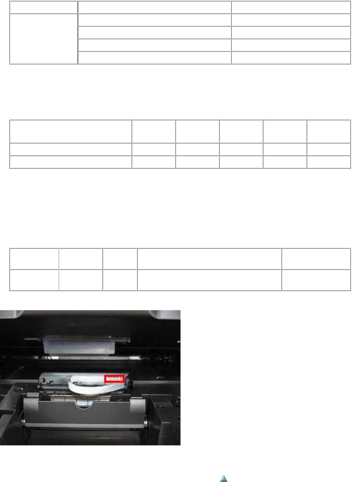
1-5. Serial Number Location
On the carriage flexible cable holder (visible on the left of the carriage: open the scanning unit after turning off the machine.)
 <1-1. MAINTENANCE>
1-3
Part 1: MAINTENANCE |
TABLE OF CONTENTS |
|
|
2. LIST OF ERROR DISPLAY / INDICATION
Errors and warnings are displayed by the following ways:
1)Operator call errors are indicated by the Alarm LED lit in orange, and the error and its solution are displayed on the LCD in text and by icon.
2)Messages during printing from a computer are displayed on the MP driver Status Monitor.
3)Error codes are printed in the "operator call/service call error record" area in EEPROM information print.
Buttons valid when an operator call error occurs:
1)ON/OFF button: To turn the machine off and on again.
2)OK button: To clear and recover from an error. In some operator call errors, the error will automatically be cleared when the cause of the error is eliminated, and pressing the OK button may not be necessary.
3)Stop/Reset button: To cancel the job at error occurrence, and to clear the error.
2-1. Operator Call Errors (by Alarm LED Lit in Orange)
Error [Error code]
No paper in the ASF. [1000]
No paper in the front paper feed cassette. [1003]
Paper jam. [1300]
Paper jam in the rear guide. [1303]
Paper jam in the under guide. [1304]
Ink may have run out. [1600]
Ink tank not installed. [1660]
-Print head not installed, or not properly installed. [1401]
-Print head temperature sensor error. [1403]
U |
|
Message on the LCD |
|
Solution |
|
Remarks |
No. |
|
|
|
|||
|
|
|
|
|
|
|
|
|
|
|
|
|
|
--- Auto sheet feeder.
There is no paper. Load paper and press [OK].
--- Cassette.
There is no paper. Load paper and press [OK].
--- Paper output slot / Rear
|
cover / Duplex transport |
|
--- |
unit. |
|
The paper is jammed. |
||
|
||
--- |
Clear the paper and |
|
press [OK]. |
||
|
U041 (Applicable ink tank icon)
The following ink may have run out. Replacing the ink tank is recommended.
Set the paper in the ASF, and press the OK button.
Set the paper in the cassette, and press the OK button.
Remove the jammed paper, and press the OK button.
Replace the applicable ink tank, or press the OK button to clear the error without ink tank replacement.
U043 |
(Applicable ink tank |
Install the applicable ink tank(s) properly, |
|
icon) |
and confirm that the LED's of all the ink |
|
The following ink tank |
tanks light red. |
|
cannot be recognized. |
|
U051 |
Print head is not |
Install the print head properly. |
|
installed. Install the print |
|
|
head. |
|
U052 |
The type of print head is |
|
|
|
1-4 |
Error during paper feeding from the ASF
Error in the duplexing transport unit
Error during paper feeding from the cassette
When the error is cleared by pressing the OK button, ink may run out during printing.

- Faulty EEPROM data of |
incorrect. Install the |
the print head. [1405] |
correct print head. |
- Print head hardware |
|
error. [1682] |
|
Inner cover open. [1841]
Inner cover open during printing on paper. [1846]
Multiple ink tanks of the same color installed. [1681]
Ink tank in a wrong position. [1680]
Warning: The ink absorber becomes almost full. [1700, 1701 (Japan)]
---Inner cover is open. Close the inner cover
---and press [OK].
U071 (Applicable ink tank icon)
More than one ink tank of the following color is installed.
U072 Some ink tanks are not installed in place.
---Contact the support center or service center for ink absorber replacement. Press [OK] to continue printing.
Close the inner cover, and press the OK button.
Close the inner cover, and press the OK button.
Replace the wrong ink tank(s) with the correct one(s).
Install the ink tank(s) in the correct position.
Press the OK button.
The service call error, indicating the ink absorber is full, is likely to occur soon.
The connected digital |
--- The device may be |
camera or digital video |
incompatible. Remove |
camera does not support |
the device and check the |
Camera Direct |
manual supplied with |
Printing. [2001] |
the connected device. |
Automatic duplex |
--- This paper is not |
printing cannot be |
compatible with duplex |
performed. [1310] |
printing. Remove the |
|
paper and press [OK]. |
Remove the cable between the camera and the machine.
Press the OK button to eject the paper being used at error occurrence. Printing will resume from on the front side of the next page.
Failed in automatic print |
--- Auto head align has |
head alignment. [2500] |
failed. |
|
Press [OK] and repeat |
|
operation. <See manual> |
Press the OK button.
-If paper is being fed at error occurrence, the error is indicated after the paper is ejected.
-If the error occurs, the print head alignment values are not changed.
-After exit from the error by the OK
1-5
Data which was to be printed on the back side of paper at error occurrence is skipped (not printed).
The error will occur (a) when the print head alignment pattern is not printed due to no ink or non-ejection of ink, (b) when the sensor's AD value is incorrect, or (c) when the paper is shorter than the specified length.
The remaining ink |
U130 (Applicable ink tank |
amount unknown. [1683] |
icon) |
|
The remaining level of |
|
the following ink cannot |
|
be correctly detected. |
|
Replace the ink tank. |
Ink tank not recognized. |
U140 |
(Applicable ink tank |
[1684] |
|
icon) |
|
|
The following ink tank |
|
|
cannot be recognized. |
Ink tank not recognized. |
U150 |
The following ink tank |
[1410 to 1419] |
|
cannot be recognized. |
|
|
(Applicable ink tank |
|
|
icon) |
No ink. [1688] |
U163 |
(Applicable ink tank |
|
|
icon) |
The following ink has run out. Replace the ink tank.
Scanning unit (printer |
--- Cover is open. Close |
cover) open. [1200] |
cover. |
button, the automatic print head alignment will not be re-done.
An ink tank which has once been empty is installed. Replace the applicable ink tank with a new one.
Printing with a once-empty ink tank can damage the printer.
To continue printing without replacing the ink tank(s), press the Stop/Reset button for 5 sec. or longer to disable the function to detect the remaining ink amount. After the operation, it is recorded in the printer EEPROM that the function to detect the remaining ink amount was disabled.
A non-supported ink tank is installed (the ink tank LED is turned off). Install the supported ink tanks.
A hardware error occurred in an ink tank (the ink tank LED is turned off). Replace the ink tank(s).
Each error code corresponds to each ink tank, from left (the opposite side of the home position) to right, respectively.
The error is indicated when raw ink is detected but the dot count number exceeds the threshold of complete exhaustion of ink.
Ink tank positioning (from left to right):
BK, PigBK, Y, M, C
Replace the empty ink tank(s), and close the scanning unit (printer cover).
Printing with an empty ink tank can damage the printer.
To continue printing without replacing the ink tank(s), press the Stop/Reset button for 5 sec. or longer to disable the function to detect the remaining ink amount. After the operation, it is recorded in the printer that the function to detect the remaining ink amount was disabled.
Close the scanning unit (printer cover).
The error is indicated when "no raw ink" is detected and when the dot count number exceeds the threshold of complete exhaustion of ink.
Printing stops because the scanning unit (printer cover) is open.
 <1-2-1. Operator Call Errors>
1-6

Part 1: MAINTENANCE |
TABLE OF CONTENTS |
|
|
2-2. Service Call Errors (by Cyclic Blinking in Orange (Alarm LED) and Green (COPY button), or Alarm LED Lit in Orange)
Service call errors are indicated by the number of cycles the Alarm LED and COPY button blink, and the corresponding error code is displayed on the LCD.
Cycles of blinking in orange
(Alarm Error LED) and
green (COPY button)
2 times |
Carriage error |
|
[5100] |
Solution (Replacement of listed Conditions parts, which are likely to be
faulty)
An error occurred in the carriage encoder signal. |
- Carriage unit (QM2-3936) |
|
- Timing slit strip film (QC1- |
|
6526) |
|
- Logic board ass'y (QM3-0250)*1 |
|
- Carriage motor (QK1-1500) |
3 times |
Line feed error |
An error occurred in the LF encoder signal. |
- Timing sensor unit (QM3-1271) |
|
[6000] |
|
- Timing slit disk film (QC2- |
|
|
|
0475) |
|
|
|
- Feed roller ass'y (QL2-1490) |
|
|
|
- Logic board ass'y (QM3-0250)*1 |
|
|
|
- Paper feed motor (QK1-1502) |
4 times |
Purge cam sensor error [5C00] |
An error occurred in the purge unit. |
- Purge unit (QM3-0033) |
|
|
|
- Logic board ass'y (QM3-0250)*1 |
5 times |
ASF (cam) sensor error [5700] |
This error takes place when feeding paper from the |
- Sheet feed unit (QM3-0064) |
|
|
ASF after an error occurred in the ASF cam sensor. |
|
6 times |
Internal temperature error [5400] |
The internal temperature is not normal. |
- Logic board ass'y (QM3-0250)*1 |
|
|
|
- Carriage unit (QM2-3936) |
7 times |
Ink absorber full [5B00, 5B01 |
The ink absorber is supposed to be full.Message on |
- Ink absorber kit (QY5-0181) |
|
(Japan)] |
the LCD: Ink absorber full. Service required. |
|
8 times |
Print head temperature rise error |
The print head temperature exceeded the specified |
- Print head (QY6-0061) |
|
[5200] |
value. |
- Logic board ass'y (QM3-0250)*1 |
9 times |
EEPROM / NVRAM error [6800] |
A problem occurred in writing to the EEPROM. |
- Logic board ass'y (QM3-0250)*1 |
10 times |
VH monitor error [B200] |
The VH output is not normal. |
- Print head (QY6-0061) |
|
|
|
- Logic board ass'y (QM3-0250)*1 |
11 times |
Carriage lift mechanism error |
The carriage did not move up or down properly. |
- PR lift shaft ass'y (QL2-1450) |
|
[5110] |
|
- Sheet feed unit (QM3-0064) |
|
|
|
- Logic board ass'y (QM3-0250)*1 |
|
|
|
- Carriage lift sensor unit (QM3- |
|
|
|
1273) |
12 times |
AP position error [6A00] |
An error occurred in the AP motor during purging |
- Sheet feed unit (QM3-0064) |
|
|
operation. |
- Logic board ass'y (QM3-0250)*1 |
|
|
|
- Purge unit (QM3-0033) |
13 times |
Paper feed position error [6B00] |
An error occurred in the paper feed motor. |
- Sheet feed unit (QM3-0064) |
|
|
|
- Logic board ass'y (QM3-0250)*1 |
14 times |
Paper feed cam sensor error |
|
[6B10] |
An error occurred in the paper feed cam sensor |
- Sheet feed unit (QM3-0064) |
during paper feeding from the front paper feed |
- Logic board ass'y (QM3-0250)*1 |
cassette. |
|
This error is also indicated when the ink absorber |
|
counter value is 60% or more, and a paper jam |
|
occurs in the under guide. |
|
1-7

15 times USB Host VBUS overcurrent |
The USB Host VBUS is overloaded. |
- Logic board ass'y (QM3-0250)*1 |
[9000] |
|
|
16 times Pump roller sensor error [5C20] |
The pump roller position cannot be detected. |
- Logic board ass'y (QM3-0250)
*1
|
|
|
- Purge unit (QM3-0033) |
17 times |
Paper eject encoder error [6010] |
An error occurred in the paper eject encoder signal. |
- Logic board ass'y (QM3-0250) |
|
|
|
*1 |
|
|
|
- Platen unit (QM3-1794) |
19 times |
Ink tank position sensor error |
None of the ink tank position is detected. |
- Platen unit (QM3-1794) |
|
[6502] |
|
- Logic board ass'y (QM3-0250)*1 |
20 times |
Other hardware error [6500] |
The PCI bus error is detected by the ASIC. |
- Logic board ass'y (QM3-0250)*1 |
22 times |
Scanner home position error |
The scanner unit cannot detect the home position, or |
- Scanner unit (QM2-3940) |
|
[5010] |
the scanner unit warming-up is not performed |
|
|
|
properly at power-on. |
|
|
|
On the LCD, "Scanner is not operating correctly." is |
|
|
|
displayed. |
|
Power |
ROM error |
The check sum value is incorrect in the ROM check |
- Logic board ass'y (QM3-0250)*1 |
LED |
|
at hard-power-on. |
|
turned off, |
|
|
|
and Alarm |
|
|
|
LED lit |
|
|
|
Power |
RAM error |
The RAM error occurred in the RAM check at hard- |
- Logic board ass'y (QM3-0250)*1 |
LED |
|
power-on. |
|
turned off, |
|
|
|
and Alarm |
|
|
|
LED lit |
|
|
|
*1: Before replacement of the logic board ass'y, check the ink absorber counter value (by service test print or EEPROM information print). If the counter value is 7% or more, also replace the ink absorber kit (QY5-0181) when replacing the logic board ass'y.
[See 3-3. Adjustment / Settings, (5) Service mode, for details.]
 <1-2-2. Service Call Errors>
1-8

Part 1: MAINTENANCE |
TABLE OF CONTENTS |
|
|
2-3. Other Error Messages
Message on the LCD
The selected paper cannot be fed from cassette. Change the paper source and press [OK].
Device memory is full. Reduce the amount of photos, films, copies to scan.
Failed to scan. Either document cannot be scanned or is not placed on the platen glass.
Press <>.
(<>: Color button icon)
Press <>.
(<>: Black button icon)
There are no photos in memory card.
Cause |
|
Solution |
The paper type being used (business card, |
|
Change the paper source to the ASF. |
Credit Card size paper, or stickers, etc.) is not |
|
|
supported for paper feeding from the cassette. |
|
|
The memory is not sufficient to do the print |
|
Reduce the amount of data to be printed, or |
job. |
|
print from a computer. |
The machine failed in scanning the document |
|
Press the OK button to clear the error. The |
for Fit-to-page copy. |
|
LCD automatically returns to the display |
|
|
before the error occurrence. |
The Black button was pressed, but it is invalid. |
|
A temporary error. Press the Color button to |
|
|
continue the operation. |
The Color button was pressed, but it is invalid. |
|
A temporary error. Press the Black button to |
|
|
continue the operation. |
Supported image files are not in the memory |
|
A temporary error. |
card. |
|
|
The value exceeds the number of copies you can print.
Memory card is not set. Insert the card after checking the direction.
During selecting images or specifying the number of copies, the total print quantity exceeds the prescribed value of 999.
No memory card is inserted in the slot.
A temporary error. The last operation before the error is cancelled, and the total print quantity returns to the value before the error.
Set a memory card.
DPOF information is not saved in the memory card.
DPOF print was selected in the menu, but no DPOF files are contained in the memory card.
A temporary error. The LCD automatically returns to the display before the error occurrence.
This layout is available only for A4 or 8.5"x11"(215x279).
In Layout print, "Mixed 1, 2, or 3" which is available only with A4 or Letter size paper is selected, but the paper size is not set to A4 or Letter.
A temporary error. The LCD automatically returns to the display before the error occurrence.
Change the setting after removing the card.
The card is currently write-enabled. Set to read-only mode before performing operation.
The paper size is not correct. Check the page size you have set.
Failed to scan handwriting sheet. Check for missed and improper markings.
Failed to scan handwriting sheet. Check orientation and position, and make sure platen and sheet are clean. <See manual>
Failed to scan Photo Index Sheet. Check for missed and improper markings.
Failed to scan Photo Index Sheet. Check the orientation, position and marking. <See manual>
With a memory card inserted in the slot, change of the Read/Write attribute was attempted.
With the memory card set to the Read/write mode, Card Direct printing operation was attempted from the menu.
Non-supported size of paper for Camera Direct printing is selected.
The machine failed in scanning the handwritten Photo Index Sheet.
A temporary error. The LCD automatically returns to the display before the error occurrence.
A temporary error. The LCD automatically returns to the display before the error occurrence.
Cancel printing on the digital camera.
Press the OK button to clear the error. The LCD automatically returns to the display before the error occurrence.
The machine failed in scanning the handwritten Photo Index Sheet.
The machine failed in scanning the Photo Index Sheet.
Press the OK button to clear the error. The LCD automatically returns to the display before the error occurrence.
Press the OK button to clear the error. The LCD automatically returns to the display before the error occurrence.
The machine failed in scanning the Photo |
Press the OK button to clear the error. The |
Index Sheet. |
LCD automatically returns to the display |
|
before the error occurrence. |
 <1-2-3. Other Error Messages>
1-9

Part 1: MAINTENANCE |
TABLE OF CONTENTS |
|
|
2-4. Warnings
Warning
Low ink
Print head temperature rise
Protection of excess rise of the print head temperature
Restrictions on paper
Message on the LCD
The following ink is low. Continue? (Icon of each ink tank)
Yes No
In Camera Direct Printing, only "Yes" can be selected.
If the print head temperature does not fall, the error code "5200" is displayed, indicating the print head temperature rise error.
If the print head temperature does not fall, the error code "5200" is displayed, indicating the print head temperature rise error.
The current paper cannot be set. Change the size and type.
Solution
- Select Yes, and press the OK button.
=> Printing starts, and it is indicated on the LCD. - Select No, and press the OK button.
=> Printing is cancelled, and the LCD returns to the display immediately before printing was attempted.
When the print head temperature falls, the error is automatically cleared.
Note: If the print head temperature exceeds the specified limit when the scanning unit (printer cover) is opened, the carriage does not move to the ink tank replacement position.
If the print head temperature exceeds the specified limit, an intermission is inserted during printing.
Re-select the supported paper type and size.
Recommendation of the print head alignment (only on arrival of the machine)
Head alignment required. Load paper and press [OK]. Yes No
- Select Yes, and press the OK button.
=> Automatic print head alignment is performed. - Select No, and press the OK button.
=> The procedures on arrival of the machine are finished.
USB cable not connected |
Connect USB cable and turn on the PC. |
Cancellation of image |
Reset the selected photo information? |
select information |
Yes |
 <1-2-4. Warnings>
Connect the USB cable.
When one or more images are selected in Multi-photo print or Layout print, and if a user tries to display the menu or sub-menu, the message is displayed.
- Select Yes, and press the OK button.
=> The image selection is cancelled, and the menu or sub-menu is displayed.
1-10

Part 1: MAINTENANCE |
TABLE OF CONTENTS |
|
|
2-5. Troubleshooting by Symptom
|
|
Symptom |
Faulty operation |
|
The power does not turn on. |
|
|
The power turns off immediately after |
|
|
power-on. |
A strange noise occurs.
Nothing is displayed on the LCD.
A portion of the LCD is not displayed.
Paper feed problems (multi-feeding, skewed feeding, no feeding).
Carriage movement problems (contact to other parts, strange noise).
Faulty scanning (no scanning, strange noise).
Unsatisfactory print quality No printing, or no color ejected.
1-11
Solution
-Confirm the connection of
-the power cord, and
-between the logic board and the power supply unit.
-Replace the
-AC adapter, or
-logic board*1.
-Remove foreign material.
-Attach a removed part if any.
-Check the operation of the moving parts (such as purge unit, carriage unit, and paper feeding mechanism)
-Replace a faulty part, if any.
-Confirm the connection between the operation panel, the scanning unit, and the logic board.
-Replace the
-LCD, or
-logic board*1.
-Perform the button and LCD test in the service mode, and confirm that the LCD is displayed without any segments missing.
-Confirm the connection between the operation panel, the scanning unit, and the logic board.
-Replace the
-LCD, or
-logic board*1.
-Examine the inside to confirm that no parts are damaged, and the rollers are clean.
-Remove foreign material.
-Adjust the paper guide properly.
-Confirm the connection of each harness and the logic board.
-Replace the
-sheet feeder unit,
-cassette, or
-logic board*1.
-Confirm that the timing slit strip film is free from damage or grease.
-Clean the timing slit strip film.
-Replace the
-timing slit strip film, or
-carriage unit.
-Remove foreign material.
-Confirm the connection between the scanning unit and the logic board.
-Replace the
-scanning unit, or
-logic board*1.
-Replace the
-ink tank,
-print head*2, or

Printing is faint, or white lines appear on printouts even after print head cleaning.
Line(s) not included in the print data appears on printouts.
Paper gets smeared.
A part of a line is missing on printouts.
Color hue is incorrect.
Printing is incorrect.
No ejection of black ink.
Graphic or text is enlarged on printouts.
Faulty scanning |
No scanning. |
Streaks or smears on the scanned image.
1-12
-logic board*1.
-Remove foreign material from the purge unit caps, if any.
-Replace the purge unit.
-Remove and re-install the print head.
-Replace the
-ink tank,
-print head*2,
-purge unit, or
-logic board*1.
-Feed several sheets of paper.
-Perform bottom plate cleaning.
-Clean the paper path with cotton swab or cloth.
-Clean the ASF sub-rollers.
-Replace the
-ink tank, or
-print head*2.
-Perform print head alignment.
-Replace the
-ink tank, or
-print head*2.
-Perform print head alignment.
Replace the logic board*1.
-Replace the
-ink tank, or
-print head*2.
-Remove foreign material from the purge unit caps, if any.
-Replace the purge unit.
When enlarged in the carriage movement direction:
-Clean grease or oil off the timing slit strip film
-Replace the
-timing slit strip film,
-carriage unit, or
-logic board*1.
When enlarged in the paper feed direction:
-Clean grease or oil off the timing slit disk film
-Replace the
-timing slit disk film,
-timing sensor unit, or
-logic board*1.
-Confirm the connection between the scanning unit and the logic board.
-Replace the
-scanning unit, or
-logic board*1.
-Clean the platen glass and the ADF.
-Confirm the connection between the scanning unit and the logic board.
-Replace the
-scanning unit,
-logic board*1.

*1: Before replacement of the logic board ass'y, check the ink absorber counter value (by service test print or EEPROM information print). If the counter value is 7% or more, also replace the ink absorber kit (QY5-0181) when replacing the logic board ass'y.
[See 3-3. Adjustment / Settings, (5) Service mode, for details.]
*2: Replace the print head only after the print head deep cleaning is performed 2 times, and when the problem persists.
 <1-2-5. Troubleshooting by Symptom>
1-13

Part 1: MAINTENANCE |
TABLE OF CONTENTS |
|
|
3. REPAIR
3-1. Notes on Service Part Replacement (and Disassembling / Reassembling)
Service part
Logic board ass'y QM3-0250
Ink absorber kit
QY5-0181
Carriage unit
QM2-3936
Paper feed motor QK1-1502
Platen unit
QM3-1794
PR lift shaft ass'y QL2-1450
Input carriage lift gear QC2-1873
Timing slit strip film QC1-6526
Notes on replacement*1 |
|
|
Adjustment / settings |
|
|
Operation check |
- Before removal of the logic |
|
After replacement: |
|
- EEPROM information print |
||
board ass'y, remove the power |
1. |
Initialize the EEPROM. |
- |
Service test print |
||
cord, and allow for approx. 1 |
2. |
Reset the ink absorber counter. |
- |
Printing via USB connection |
||
minute (for discharge of |
3. |
Set the destination in the |
- |
Direct printing from a digital |
||
capacitor's accumulated |
|
|
EEPROM. |
|
|
camera |
charges), to prevent damages to |
4. |
Correct the CD / DVD and |
|
|
|
|
the logic board ass'y. |
|
|
automatic print head alignment |
|
|
|
- Before replacement, check the |
|
|
sensors. |
|
|
|
ink absorber counter value (by |
5. |
Check the ink system function. |
|
|
|
|
service test print or EEPROM |
|
|
[See 3-3. Adjustment / Settings, |
|
|
|
information print). If the value is |
|
|
(5) Service mode, for details of 1 |
|
|
|
7% or more, also replace the ink |
|
|
to 5.] |
|
|
|
absorber kit (QY5-0181) when |
6. |
Perform the print head |
|
|
|
|
replacing the logic board ass'y. |
|
|
alignment in the user mode. |
|
|
|
[See 3-3. Adjustment / Settings, |
|
|
|
|
|
|
(5) Service mode, for details.] |
|
|
|
|
|
|
|
|
After replacement: |
- |
Service test print |
||
|
1. |
Reset the ink absorber counter. |
- |
EEPROM information print |
||
|
|
|
[See 3-3. Adjustment / Settings, |
|
|
|
|
|
|
(5) Service mode, for details.] |
|
|
|
-The red screws securing the paper feed motor are allowed to be loosened. (DO NOT loosen any other red screws.)
At replacement: |
- Service test print (Confirm |
1. Apply grease to the sliding |
automatic print head |
portions. |
alignment sensor correction, |
[See 3-3. Adjustment / Settings, |
and ink system function.) |
(2) Grease application.] |
|
After replacement:
1.Correct the automatic print head alignment sensors.
[See 3-3. Adjustment / Settings,
(5)Service mode, for details.]
2.Check the ink system function. [See 3-3. Adjustment / Settings,
(5)Service mode, for details.]
3.Perform the print head alignment in the user mode.
At replacement: |
|
|
1. |
Adjust the paper feed motor. |
|
|
[See 3-3. Adjustment / Settings, |
|
|
(1) Paper feed motor |
|
|
adjustment.] |
|
After replacement: |
- Service test print |
|
1. |
Check the ink system function. |
|
|
[See 3-3. Adjustment / Settings, |
|
|
(5) Service mode, for details.] |
|
At replacement: |
- Service test print |
|
1. |
Apply grease to the sliding |
|
|
portions. |
|
|
[See 3.3. Adjustment / Settings, |
|
|
(2) Grease application.] |
|
- Upon contact with the film, wipe |
After replacement: |
- Service test print |
the film with ethanol. |
1. Perform the print head |
|
1-14

Timing slit disk eject film QC2-0476
Timing slit disk film QC2-0475
Print head
QY6-0061
*1: General notes:
- Confirm no grease is on the film. alignment in the user mode. (Wipe off any grease thoroughly
with ethanol.)
- Do not bend the film |
|
After replacement: |
- Service test print |
1. Perform the print head |
|
alignment in the user mode. |
|
-Make sure that the flexible cables and wires in the harness are in the proper position and connected correctly. [See 3-2. Special Notes on Repair Servicing, (5) Flexible cable and harness wiring, connection, for details.]
-Do not drop the ferrite core, which may cause damage.
-Protect electrical parts from damage due to static electricity.
-Before removing a unit, after removing the power cord, allow the machine to sit for approx. 1 minute (for capacitor discharging to protect the logic board ass'y from damages).
-Do not touch the timing slit strip film, timing slit disk film, and timing slit disk eject film. No grease or abrasion is allowed.
-Protect the units from soiled with ink.
-Protect the housing from scratches.
-Exercise caution with the red screws, as follows:
i.The red screws of the paper feed motor may be loosened only at replacement of the paper feed motor unit (DO NOT loosen them in other cases).
ii.DO NOT loosen the red screws on both sides of the main chassis, securing the carriage shaft positioning (they are not adjustable in servicing)
 <1-3-1. Notes on Service Part Replacement>
1-15
Part 1: MAINTENANCE |
TABLE OF CONTENTS |
|
|
3-2. Special Notes on Repair Servicing
(1) External cover and scanner unit removal
(i) Front cover L removal
Insert a flat-blade screwdriver in the location indicated by the red circle, and release the front cover L while pushing it upward using the screwdriver.
(ii) Front cover R removal
Insert the flat-blade screwdriver in the location indicated by the red circle, and release the front cover R in the same way as step
(i).
(iii) Remove 4 screws from the back of the machine, and 2 screws from the top back.
1-16

(iv) Remove 2 screws from the front of the machine (1 each on the right and left sides).
(v) Remove the side covers L and R.
(vi) Scanner lock arm unit removal
Push the main case tab outward to unlock the unit.
When assembling the scanner lock arm unit, make sure that the unit is in the correct orientation.
1-17
Loading...