


MX7600
Service Manual
Revision 0
QY8-13BU-000
COPYRIGHTc2008 CANON INC. CANON MX7600 032008 XX 0.00-0
Scope
This manual has been issued by Canon Inc., to provide the service technicians of this product with the information necessary for qualified persons to learn technical theory, installation, maintenance, and repair of products. The manual covers information applicable in all regions where the product is sold. For this reason, it may contain information that is not applicable to your region.
This manual does not provide sufficient information for disassembly and reassembly procedures. Refer to the graphics in the separate Parts Catalog.
Revision
This manual could include technical inaccuracies or typographical errors due to improvements or changes made to the product. When changes are made to the contents of the manual, Canon will release technical information when necessary. When substantial changes are made to the contents of the manual, Canon will issue a revised edition.
The following do not apply if they do not conform to the laws and regulations of the region where the manual or product is used:
Trademarks
Product and brand names appearing in this manual are registered trademarks or trademarks of the respective holders.
Copyright
All rights reserved. No parts of this manual may be reproduced in any form or by any means or translated into another language without the written permission of Canon Inc., except in the case of internal business use.
Copyright © 2008 by Canon Inc. CANON INC.
Inkjet Device Quality Assurance Div. 2
451, Tsukagoshi 3-chome, Saiwai-ku, Kawasaki-shi, Kanagawa 212-8530, Japan

MX7600
TABLE OF CONTENTS
1. MAINTENANCE
1-1. Adjustment, Periodic Maintenance, Periodic Replacement Parts, and Replacement Consumables by Service Engineer
1-2. Customer Maintenance
1-3. Special Tools
1-4. Serial Number Location
2. LIST OF ERROR DISPLAY / INDICATION
2-1. Operator Call Errors
2-2. Service Call Errors
2-3. Fax Errors
2-4. Other Error Messages
2-5. Warnings
2-6. Troubleshooting by Symptom
3. REPAIR
3-1. Notes on Service Part Replacement
3-2. Special Notes on Repair Servicing
(1)External housing, ADF, and scanner unit removal
(2)Printer unit separation from the bottom case (how to remove the screw under the purge unit)
(3)Operation panel removal
(4)AC adapter removal
(5)Emblem removal
(6)Positioning of the RCT pump valve unit tube
(7)Cable wiring and connecter connection
3-3. Adjustment / Settings
(1)Paper feed motor adjustment
(2)Grease application
(3)Ink absorber counter setting
(4)User mode
(5)Service mode
A:Service mode operation
B:Destination settings
C:Ink absorber counter resetting
D:Wetting liquid counter resetting
E:Ink absorber counter setting
F:LF / Eject correction
G:Button and LCD test
(6)PTT parameter mode
A:PTT parameter mode operation
B:#1 BIT SWITCH
C:#2 NUMERIC PARAM
D:Confirmation of the setting values
3-4. Verification Items
(1)Service test print
(2)Ink absorber counter value print
4.MACHINE TRANSPORTATION
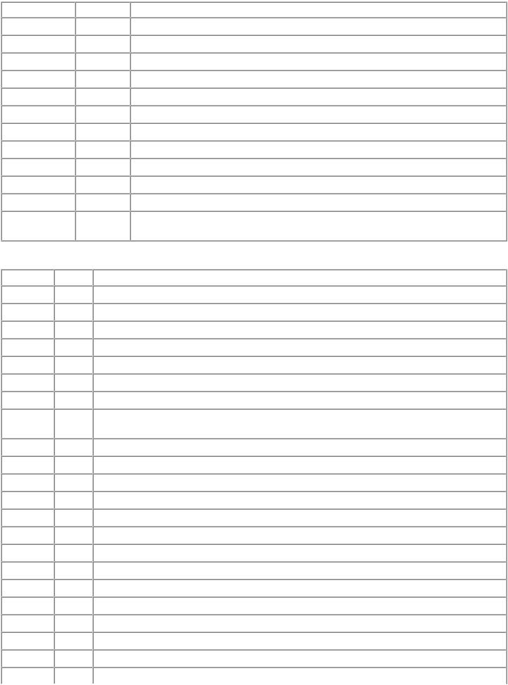
 <TABLE OF CONTENTS>

MX7600 |
TABLE OF CONTENTS |
|
|
1. MAINTENANCE
1-1. Adjustment, Periodic Maintenance, Periodic Replacement Parts, and Replacement Consumables by Service Engineer
(1) Adjustment
|
|
Adjustment |
|
Timing |
|
Purpose |
|
Tool |
|
Approx. |
|
|
|
|
|
|
time |
||||
|
|
|
|
|
|
|
|
|
|
|
|
|
EEPROM |
|
- At logic board replacement |
|
To initialize settings |
|
None. |
|
1 min. |
|
|
initialization |
|
|
|
|
|
Perform in the service |
|
|
|
|
|
|
|
|
|
|
mode. |
|
|
|
|
Destination |
|
- At logic board replacement |
|
To set destination. |
|
None. |
|
1 min. |
|
|
settings (EEPROM |
|
|
|
|
|
Perform in the service |
|
|
|
|
settings) |
|
|
|
|
|
mode. |
|
|
|
|
Ink absorber |
|
- At logic board replacement |
|
To reset the ink absorber or |
|
None. |
|
1 min. |
|
|
counter / wetting |
|
- At ink absorber |
|
wetting liquid counter. |
|
Perform in the service |
|
|
|
|
liquid counter |
|
replacement*1 |
|
|
|
mode. |
|
|
|
|
resetting |
|
- At wetting liquid unit |
|
|
|
|
|
|
|
|
(EEPROM |
|
replacement*1 |
|
|
|
|
|
|
|
|
settings) |
|
|
|
|
|
|
|
|
|
|
Ink absorber |
|
- At logic board replacement |
|
To set the ink amount data in |
|
None. |
|
1 min. |
|
|
counter value |
|
|
|
the ink absorber to the ink |
|
Perform in the service |
|
|
|
|
setting |
|
|
|
absorber counter. |
|
mode. |
|
|
|
|
(EEPROM |
|
|
|
|
|
|
|
|
|
|
settings) |
|
|
|
|
|
|
|
|
|
|
Ink absorber / |
|
- When the ink absorber |
|
To replace the ink absorber or |
|
Screwdriver, a pair of |
|
20 min. |
|
|
wetting liquid unit |
|
becomes full*1 |
|
the wetting liquid unit with a |
|
tweezers, etc. |
|
|
|
|
replacement |
|
- When the wetting liquid unit |
|
new one. |
|
|
|
|
|
|
|
|
becomes empty*1 |
|
|
|
|
|
|
|
|
Paper feed motor |
|
- At paper feed motor |
|
To adjust the belt tension. |
|
None. |
|
5 min. |
|
|
position |
|
replacement |
|
(Position the paper feed motor |
|
|
|
|
|
|
adjustment |
|
|
|
so that the belt is stretched |
|
|
|
|
|
|
|
|
|
|
tight.) |
|
|
|
|
Automatic print |
- At print head replacement |
head alignment |
- At logic board replacement |
|
- When print quality is not |
|
satisfying |
To secure the dot placement accuracy.
4 sheets of plain paper. 9 min. Perform in the user
mode.
Manual print head |
- At print head replacement |
alignment |
- At logic board replacement |
|
- When print quality is not |
|
satisfying |
To secure the dot placement accuracy.
2 sheets of plain paper. 10 min. Perform in the user
mode.
Grease application |
- At carriage unit replacement |
To maintain sliding properties |
FLOIL KG-107A |
1 min. |
|
- At lift cam replacement |
of the following items: |
|
|
|
- To gears |
- Carriage shaft |
|
|
|
|
- Lift cam bushing |
|
|
|
|
- Machine sliding portions |
|
|
|
|
(gears) |
|
|
Ink system |
- At logic board replacement |
To maintain detection |
None. |
1 min. |
function check |
- At spur base replacement |
functionality for presence of the |
Perform in the service |
|
|
- At carriage unit replacement |
ink tanks and each ink tank |
mode. |
|
|
|
position. |
|
|
LCD language |
- At logic board replacement |
To set the language to be |
None. |
1 min. |
settings |
|
displayed on the LCD. |
Perform in the user |
|
|
|
1 / 65 |
|
|

|
|
|
mode. |
LF / Eject |
- At logic board replacement |
To correct line feeding (LF |
None. |
correction |
- At feed roller ass'y |
roller diameter). |
Perform in the service |
|
replacement |
|
mode. |
|
- At logic board replacement |
To correct line feeding (eject |
None. |
|
- At platen unit replacement |
roller diameter). |
Perform in the service |
|
|
|
mode. |
5 min. (LF correction and Eject correction is performed at the same time.)
LAN resetting |
- At protection sheet |
To initialize the network setting. |
None. |
1 min. |
|
replacement |
|
Perform in the user |
|
|
|
|
mode. |
|
|
|
|
- Machine buttons |
|
|
|
|
- Computer (IJ Network |
|
|
|
|
tool) |
|
LAN setting |
- At confirmation of the |
To confirm the network setting. |
None. |
1 min. |
information |
network setting (as needed) |
|
Perform in the user |
|
display |
|
|
mode. |
|
|
|
|
- Machine buttons |
|
|
|
|
- Computer (IJ Network |
|
|
|
|
tool) |
|
*1: The ink absorber and wetting liquid unit should be replaced at the same time.
-DO NOT loosen the red screws at both ends of the carriage shaft, securing the print head position, as they are not re-adjustable.
-The red screws securing the paper feed motor may be loosened only at replacement of the paper feed motor unit.
(2)Periodic maintenance
No periodic maintenance is necessary.
(3) Periodic replacement parts
There are no parts in this machine that require periodic replacement by a service engineer.
(4) Replacement consumables
There are no consumables that require replacement by a service engineer.
2 / 65

1-2. Customer Maintenance
Adjustment |
|
Timing |
|
Purpose |
|
Tool |
|
Approx. |
|
|
|
|
time |
||||
|
|
|
|
|
|
|
|
|
Automatic print head |
|
- At print head replacement |
|
To ensure accurate dot |
|
- Machine |
|
9 min. |
alignment |
|
- When print quality is not satisfying |
|
placement. |
|
buttons |
|
|
|
|
(uneven printing, etc.) |
|
|
|
- Plain paper |
|
|
|
|
|
|
|
|
- Computer |
|
|
|
|
|
|
|
|
(MP driver) |
|
|
Manual print head |
|
- At print head replacement |
|
To ensure accurate dot |
|
- Machine |
|
10 min. |
alignment |
|
- When print quality is not satisfying |
|
placement. |
|
buttons |
|
|
|
|
(uneven printing, etc.) |
|
|
|
- Plain paper |
|
|
|
|
|
|
|
|
- Computer |
|
|
|
|
|
|
|
|
(MP driver) |
|
|
Print head cleaning |
|
When print quality is not satisfying. |
|
To improve nozzle |
|
- Machine |
|
1 min. |
|
|
|
|
conditions. |
|
buttons |
|
|
|
|
|
|
|
|
- Computer |
|
|
|
|
|
|
|
|
(MP driver) |
|
|
Print head deep |
|
When print quality is not satisfying, and |
|
To improve nozzle |
|
- Machine |
|
2 min. |
cleaning |
|
not improved by print head cleaning. |
|
conditions. |
|
buttons |
|
|
|
|
|
|
|
|
- Computer |
|
|
|
|
|
|
|
|
(MP driver) |
|
|
Ink tank replacement |
When an ink tank becomes empty. ("No |
|
ink error" displayed on the monitor or on |
|
the machine LCD, or short flashing of an |
|
ink tank LED) |
To replace the empty ink |
--- |
1 min. |
tank. |
|
|
Pick-up roller cleaning |
- When paper does not feed properly. |
To clean the pick-up rollers |
- Machine |
2 min. |
(Roller cleaning) |
- When the front side of the paper is |
of the rear tray. |
buttons |
|
|
smeared. |
|
- Computer |
|
|
|
|
(MP driver) |
|
Rear tray sub-roller |
When the paper fed from the rear tray is |
cleaning |
smeared due to ink mist attached to the |
|
rear tray sub-rollers. |
Bottom plate cleaning |
When the back side of the paper is |
|
smeared. |
To clean the rear tray sub- |
- Machine |
1 min. |
rollers. |
buttons |
|
To clean the platen ribs. |
- Machine |
1 min. |
|
buttons |
|
|
- Computer |
|
|
(MP driver) |
|
Scanning area cleaning |
When the platen glass or document |
|
pressure sheet is dirty. |
Exterior cleaning |
When necessary |
Paper feed roller |
When "The transport unit may not be |
cleaning |
clean." is displayed. |
(Sheet cleaning) |
Perform cleaning using the cleaning sheet. |
Ink quality maintenance |
One time per week (when no printing is |
(automatic maintenance |
performed for a week) |
at default) |
|
To clean the platen glass and |
Soft, dry, and |
1 min. |
pressure sheet. |
clean lint-free |
|
|
cloth. |
|
To clean the machine |
Soft, dry, and |
1 min. |
exterior. |
clean lint-free |
|
|
cloth. |
|
To clean the paper feed |
- Machine |
2 min. |
rollers. |
buttons |
|
|
- Computer |
|
|
(MP driver) |
|
To prevent pigment |
- Machine |
10 sec. to |
components from settling to |
buttons |
2 min. |
the bottom, and to equalize |
- Computer |
|
ink density |
(MP driver) |
|
3 / 65

1-3. Special Tools
Name |
|
Tool No. |
|
Application |
|
Remarks |
FLOIL KG-107A |
|
QY9-0057-000 |
|
To the carriage shaft sliding portions and lift cam bushing. |
|
In common with the MP610, etc. |
1-4. Serial Number Location
On the carriage flexible cable holder (visible on the right of the carriage after the machine is turned on, the scanning unit is opened, and the carriage stops at the ink tank replacement position)
 <1. MAINTENANCE>
4 / 65

MX7600 |
TABLE OF CONTENTS |
|
|
2. LIST OF ERROR DISPLAY / INDICATION
Errors and warnings are displayed by the following ways:
1.Operator call errors are indicated by the Alarm LED lit in orange, and the error and its solution are displayed on the LCD in text and by icon.
2.Messages during printing from a computer are displayed on the MP driver Status Monitor.
3.Error codes are printed in the "operator call/service call error record" area in EEPROM information print
Buttons valid when an operator call error occurs:
1.ON/OFF button: To turn the machine off and on again.
2.OK button: To clear and recover from an error. In some operator call errors, the error will automatically be cleared when the cause of the error is eliminated, and pressing the OK button may not be necessary.
3.Stop/Reset button: To cancel the job at error occurrence, and to clear the error.
2-1. Operator Call Errors (by Alarm LED Lit in Orange)
Error
No paper in the rear tray.
No paper in the cassette.
Paper jam.
Paper jam in the rear guide (when paper feeding from the cassette).
Error
code
[1000]
[1003]
[1300]
[1303]
U No. |
|
Message on the LCD |
|
Solution |
|
|
|
||
|
|
|
|
|
--- |
|
Rear tray. |
|
Confirm that the rear tray is selected as the paper source. |
|
|
There is no paper. Load paper |
|
Set the paper in the rear tray, and press the OK button. |
|
|
and press [OK]. |
|
|
--- |
|
Cassette. |
|
Confirm that the cassette is selected as the paper source. |
|
|
There is no paper. Load paper |
|
Set the paper in the cassette, and press the OK button. |
|
|
and press [OK]. |
|
|
--- The paper is jammed. Clear |
|
Remove the jammed paper, and press the OK button. |
||
---the paper and press [OK].
Paper jam in the [1304] ---
under guide (during automatic duplex printing).
Ink may have run |
[1600] |
U041 |
The ink may have run out. |
out. |
|
U044 |
Replacing the ink tank is |
|
|
|
recommended. |
Ink tank not installed. |
[1660] |
U043 |
The following ink tank cannot |
|
|
|
be recognized. |
|
|
|
(Applicable ink tank icon) |
No Clear ink. |
[1692] |
U045 |
The clear ink tank is empty. |
Print head not |
[1401] |
U051 Print head is not installed. |
|
installed, or not |
|
Install the print head. |
|
properly installed. |
|
|
|
Faulty print head ID. |
[1401] |
U052 The type of print head is |
|
Print head |
[1403] |
incorrect. Install the correct |
|
print head. |
|||
temperature sensor |
|
||
|
|
||
error. |
|
|
|
Faulty EEPROM data |
[1405] |
|
|
|
|
5 / 65 |
Replace the applicable ink tank, or press the OK button to clear the error without ink tank replacement. When the error is cleared by pressing the OK button, ink may run out during printing.
Install the applicable ink tank(s) properly, and confirm that the LED's of all the ink tanks light red.
Replace the Clear ink tank with a new one, or press the OK button to continue printing without Clear ink tank replacement. However, when Clear ink is completely used up, no further printing on plain paper can be performed unless the empty Clear ink tank is replaced with a new one.
Install the print head properly.
Re-set the print head. If the error is not cleared, the print head may be defective. Replace the print head.

of the print head. |
|
Multiple ink tanks of |
[1681] U071 More than one ink tank of the Replace the wrong ink tank(s) with the correct one(s). |
the same color |
following color is installed. |
installed. |
|
Ink tank in a wrong |
[1680] |
U072 |
Some ink tanks are not |
position. |
|
|
installed in place. |
Warning: The ink |
[1700, |
--- |
Contact the support center or |
absorber becomes |
1701] |
|
service center for ink absorber |
almost full. |
|
|
replacement. Press [OK] to |
|
|
|
continue printing. |
Install the ink tank(s) in the correct position.
Replace the ink absorber, and reset its counter. [See 3-3. Adjustment / Settings, (5) Service mode.]
Pressing the OK button will exit the error, and enable printing without replacing the ink absorber. However, when the ink absorber becomes full, no further printing can be performed unless the applicable ink absorber is replaced.
The connected digital |
[2001] |
--- The device may be |
camera or digital |
|
incompatible. Remove the |
video camera does |
|
device and check the manual |
not support Camera |
|
supplied with the connected |
Direct Printing. |
|
device. |
Automatic duplex |
[1310] |
--- This paper is not compatible |
printing cannot be |
|
with duplex printing. Remove |
performed. |
|
the paper and press [OK]. |
Remove the cable between the camera and the machine.
The paper length is not supported for duplex printing. Press the OK button to eject the paper being used at error occurrence.
Data which was to be printed on the back side of paper at error occurrence is skipped (not printed).
Failed in automatic |
[2500] |
--- Auto head align has failed. |
Press the OK button to clear the error, then perform the |
print head alignment. |
|
Press [OK] and repeat |
automatic print head again. |
|
|
operation. <See manual> |
(In the MX7600, use plain paper.) |
Dirty paper feed |
[2600] |
--- The transport unit may not be |
roller. |
|
clean. Perform sheet cleaning. |
|
|
<See manual> |
When the time to perform periodic cleaning of the paper feed rollers comes, the message is displayed for several seconds during printing.
Ink tank not |
[1684] |
U140 |
The following ink tank cannot |
A non-supported ink tank is installed (the ink tank LED is |
recognized. |
|
|
be recognized. |
turned off). Install the supported ink tanks. |
|
|
|
(Applicable ink tank icon) |
|
Ink tank not |
[141#] |
U150 |
The following ink tank cannot |
A hardware error occurred in an ink tank (the ink tank |
recognized. |
|
|
be recognized. |
LED is turned off). Replace the ink tank(s). |
|
|
|
(Applicable ink tank icon) |
|
No Clear ink at all |
[1693] U165 The clear ink has run out. |
|
Replace the ink tank. |
No Clear ink at all, |
[1694] |
U166 |
The clear ink has run out. |
and the error cannot |
|
|
Replace the ink tank. |
be cleared. |
|
|
|
No ink (no raw ink). |
[1688] |
U171 |
The ink has run out. Stop |
|
|
|
printing, then |
|
|
|
replace the ink tank. |
6 / 65
Replace the Clear ink tank, or press the Stop/Reset button to clear the error without replacing the Clear ink tank. When the Stop/Reset button is pressed, printing being performed at error occurrence is cancelled.
Without the Clear ink, the print quality on plain paper becomes significantly low, and the paper feed mechanism of the cassette can be damaged. For this reason, printing on plain paper cannot be performed unless the applicable Clear ink tank is replaced with a new one.
If the Clear ink is completely used up when the machine is forcibly turned off, such as by disconnecting the power cord before the machine is turned off by the ON/OFF button, the error may not be cleared. Replace the Clear ink tank with a new one.
The PGI-7BK ink is used up (the ink tank LED flashes). Press the Stop/Reset button to stop printing, replace the empty ink tank(s), then resume printing.
Printing with an empty ink tank can damage the machine. To continue printing without replacing the ink tank(s), press the Stop/Reset button for 5 sec. or longer to disable the function to detect the remaining ink amount. After the operation, it is recorded in the machine that the function to detect the remaining ink amount was disabled.

No ink (no raw ink). |
[1698] |
U172 |
The ink has run out. Stop |
The PGI-9PBK, PGI-9Y, PGI-9M, or PGI-9C ink is used |
|
|
|
printing, then |
up (the applicable ink tank LED flashes). Press the |
|
|
|
replace the ink tank. |
Stop/Reset button to stop printing, replace the empty ink |
|
|
|
(Applicable ink tank icon) |
tank(s), then resume printing. |
|
|
|
|
To prevent faulty printing such as ink mixture, the error is |
|
|
|
|
indicated and printing is stopped when the remaining ink |
|
|
|
|
amount in the ink tank becomes lower than the amount |
|
|
|
|
required to maintain the print quality. |
Unknown ink. |
[1689] |
U181 |
The ink has run out. Stop |
The PGI-7BK ink is detected to be used up (the ink tank |
|
|
|
printing, then |
LED flashes). Stop printing, replace the ink tank, then |
|
|
|
replace the ink tank. |
resume printing. The ink tank must be replaced before |
|
|
|
|
resuming printing. |
|
|
|
|
An ink tank which has once been empty is installed. |
|
|
|
|
Printing with a once-empty ink tank can cause faulty |
|
|
|
|
printing such as improper ink mixture, or it can damage |
|
|
|
|
the machine. To continue printing without replacing the |
|
|
|
|
ink tank, press the Stop/Reset button for 5 sec. or longer |
|
|
|
|
to disable the function to detect the remaining ink amount. |
|
|
|
|
After the operation, it is recorded in the machine that the |
|
|
|
|
function to detect the remaining ink amount was disabled. |
Unknown ink. |
[1699] |
U182 |
The ink has run out. Stop |
The PGI-9PBK, PGI-9Y, PGI-9M, or PGI-9C ink is |
|
|
|
printing, then |
detected to be used up (the applicable ink tank LED |
|
|
|
replace the ink tank. |
flashes). Stop printing, replace the ink tank, then resume |
|
|
|
(Applicable ink tank icon) |
printing. The ink tank must be replaced before resuming |
|
|
|
|
printing. |
|
|
|
|
An ink tank which has once been empty is installed. |
|
|
|
|
Printing with a once-empty ink tank can cause faulty |
|
|
|
|
printing such as improper ink mixture, or it can damage |
|
|
|
|
the machine. To continue printing without replacing the |
|
|
|
|
ink tank(s), press the Stop/Reset button for 5 sec. or |
|
|
|
|
longer to disable the function to detect the remaining ink |
|
|
|
|
amount. After the operation, it is recorded in the machine |
|
|
|
|
that the function to detect the remaining ink amount was |
|
|
|
|
disabled. |
Non-supported hub. |
[2002] |
--- |
An unsupported USB hub is |
Remove the applicable USB hub from the PictBridge |
|
|
|
connected. Remove the hub. |
(USB) connector. |
No paper in the |
--- |
--- |
|
1. Press the Stop./Reset button. |
ADF, |
|
|
|
2. Except the document page stuck in the ADF, remove |
Paper jam in the |
|
|
|
all the other pages from the ADF, and open the |
ADF, |
|
|
|
document feeder cover. |
Non-supported length |
|
|
|
3. Raise the lever to release the paper, and pull out the |
of paper in the ADF |
|
|
|
stuck paper from under the pick-up roller to the |
(too long or too |
|
|
|
document feeder cover side. |
short). |
|
|
|
4. Pull out the stuck paper from the ADF. |
|
|
|
|
5. Lower the lever, and close the document feeder cover. |
|
|
|
Document in ADF. Redo |
The document is jammed in the ADF. Remove the |
|
|
|
operation after |
jammed document, press the OK button, then perform the |
|
|
|
checking document in ADF |
operation again. |
|
|
|
and pressing [OK]. |
|
Document size is too long. Redo operation after checking document on ADF and pressing [OK].
The document page is too long, or it is jammed in the ADF. Remove the document from the ADF, and press the OK button to clear the error. Confirm that the document length is supported, and perform the operation again.
7 / 65

2-2. Service Call Errors (by Cyclic Blinking of Alarm and Power LEDs)
Service call errors are indicated by the number of cycles the Alarm and Power LEDs blink, and the corresponding error code is displayed on the LCD.
Cycles of |
|
|
blinking of |
|
Error |
Alarm and |
|
|
|
|
|
Power LEDs |
|
|
2 times |
|
Carriage error |
Error |
|
Conditions |
code |
|
|
|
|
|
|
|
|
[5100] An error occurred in the carriage encoder signal.
Solution (Replacement of listed parts, which are likely to be faulty)
-Carriage unit
-Timing slit film
-Logic board
-Carriage motor
3 times |
Line feed error |
[6000] |
An error occurred in the LF encoder |
- Timing sensor unit |
|
|
|
signal. |
- Timing slit disk film |
|
|
|
|
- Feed roller |
|
|
|
|
- Logic board |
|
|
|
|
- Paper feed motor |
4 times |
Purge cam sensor error |
[5C00] |
An error occurred in the purge unit. |
- Purge unit |
|
|
|
|
- Logic board |
5 times |
ASF (cam) sensor error |
[5700] |
This error takes place when paper feeds |
- Sheet feed unit |
|
|
|
from the rear tray after an error |
- ASF_PE sensor board |
|
|
|
occurred in the ASF cam sensor. |
- Logic board |
6 times |
Internal temperature |
[5400] |
The internal temperature is not normal. |
- Logic board |
|
error |
|
|
|
7 times |
Ink absorber full |
[5B00, |
The ink absorber is supposed to be full. |
- Ink absorber kit |
|
|
5B01] |
Message on the LCD: |
|
|
|
|
Ink absorber full. Service required. |
|
|
|
|
Error codes: |
|
|
|
|
5B00: Main ink absorber is full |
|
|
|
|
(overseas). |
|
|
|
|
5B01: Main ink absorber is full |
|
|
|
|
(Japan). |
|
|
No wetting liquid |
[5250] |
The wetting liquid is used up. |
- Blade cleaner unit |
8 times |
Print head temperature |
[5200] |
The print head temperature exceeded the |
- Print head |
|
rise error |
|
specified value. |
- Logic board |
|
Reactor error |
[B300] |
A hardware error in supply of the reactor |
- Valve unit |
|
|
|
liquid. |
- Sheet feed unit |
9 times |
EEPROM error |
[6800, |
A problem occurred in reading from or |
- Logic board |
|
|
6801] |
writing to the EEPROM. |
|
|
|
|
Error codes: |
|
|
|
|
6800: Read error |
|
|
|
|
6801: Write error |
|
10 times |
VH monitor error |
[B200] |
The VH output of the power supply to |
- Print head |
|
|
|
drive the print head is abnormal. |
- Carriage unit |
|
|
|
|
- Logic board |
11 times |
Carriage lift mechanism |
[5110] |
The carriage did not move up or down |
- Sheet feed unit |
|
error |
|
properly. |
- PR lift shaft ass'y |
|
|
|
|
- Carriage lift sensor unit |
|
|
|
|
- Logic board |
12 times |
AP position error |
[6A00] |
An error occurred in the AP motor |
- Sheet feed unit |
|
|
|
during purging operation. |
- Purge unit |
|
|
|
|
- Logic board |
13 times |
PF / RR position error |
[6B00, |
6B00: An error occurred in the paper |
- Sheet feed unit |
|
|
B310] |
feed motor during line feeding. |
- Logic board |
|
|
|
8 / 65 |
|
B310: An error occurred in the reactor roller during rotation of the reactor motor.
14 times |
Paper feed cam sensor |
[6B10] |
An error occurred in the paper feed cam |
- Sheet feed unit |
|
error |
|
sensor during paper feeding from the |
- Logic board |
|
|
|
cassette. |
|
15 times |
USB Host VBUS |
[9000] |
The USB Host VBUS is overloaded. |
- Logic board |
|
overcurrent |
|
|
|
16 times |
Pump roller sensor error |
[5C20] |
The pump roller position cannot be |
- Purge unit |
|
|
|
detected. |
- Logic board |
17 times |
Paper eject encoder error |
[6010] |
An error occurred in the paper eject |
- Platen unit |
|
|
|
encoder signal. |
- Timing sensor unit |
|
|
|
|
- Timing slit disk eject film |
|
|
|
|
- Paper feed motor |
|
|
|
|
- Logic board |
19 times |
Ink tank position sensor |
[6502] |
None of the ink tank position is detected. - Platen unit |
|
|
error |
|
|
- Logic board |
22 times |
Scanner home position |
[5010] |
The scanner unit cannot detect the home |
- Scanner unit |
|
error |
|
position, or the scanner unit warming-up |
- Logic board |
|
|
|
is not performed properly at power-on. |
|
|
|
|
On the LCD, "Scanner is not operating |
|
|
|
|
correctly." is displayed. |
|
Power LED |
ROM / RAM error |
--- |
The check sum value is incorrect in the |
- Logic board |
turned off, and |
|
|
ROM check or RAM check at hard- |
|
Alarm LED lit |
|
|
power-on. |
|
Before replacement of the logic board ass'y, check the ink absorber counter value (by service test print or EEPROM information print). If the counter value is 7% or more, also replace the ink absorber kit when replacing the logic board ass'y. If the counter value is less than 7%, register the current ink absorber counter value to the replaced new logic board instead.
[See 3-3. Adjustment / Settings, (5) Service mode, for details.]
9 / 65
2-3. Fax Errors
For errors other than those listed below, please refer to the "G3 / G4 Facsimile Error Code List (Rev. 2)."
(1) User error codes
Error code |
|
TX / RX |
|
Meaning |
#001 |
|
TX |
|
Document jam |
#003 |
|
TX / RX |
|
Document is too long, or page time-over |
#005 |
|
TX / RX |
|
Initial identification (T0 / T1) time-over |
#009 |
|
RX |
|
Recording paper jam, or no recording paper |
#012 |
|
TX |
|
No recording paper at the receiving machine |
#017 |
|
TX |
|
Redial time-over, but no DT detected |
#018 |
|
TX |
|
Auto dialing transmission error, or redial time-over |
#022 |
|
TX |
|
Call failed (no dial registration) |
#037 |
|
RX |
|
Memory overflow at reception of an image |
#085 |
|
TX |
|
No color fax function supported in the receiving machine |
#099 |
|
TX / RX |
|
Transmission terminated mid-way by pressing the Stop/Reset button |
#995 |
|
TX / RX |
|
During TX (sending): Memory transmission reservation cancelled |
|
|
|
|
During RX (receiving): Image data received in the memory cleared |
(2) Service error codes
Error code |
|
TX / RX |
|
Meaning |
##100 |
|
TX |
|
Re-transmission of the procedure signal has been attempted the specified number of times, but failed. |
##101 |
|
TX / RX |
|
Sender's modem speed does not match the receiving machine. |
##102 |
|
TX |
|
Fallback is not available. |
##103 |
|
RX |
|
EOL has not been detected for 5 seconds (or 15 seconds in CBT). |
##104 |
|
TX |
|
RTN or PIN has been received. |
##106 |
|
RX |
|
The procedure signal has been expected for 6 seconds, but not received. |
##107 |
|
RX |
|
Fallback is not available at the sending machine. |
##109 |
|
TX |
|
After DCS transmission, a signal other than DIS, DTC, FTT, CFR, or CRP has been received, and re- |
|
|
|
|
transmission of the procedure signal has been attempted the specified number of times but failed. |
##111 |
|
TX / RX |
|
Memory error |
##114 |
|
RX |
|
RTN has been received. |
##200 |
|
RX |
|
A carrier has not been detected for 5 seconds during image reception. |
##201 |
|
TX / RX |
|
DCN has been received in a method other than the binary procedure. |
##204 |
|
TX |
|
DTC has been received even when there is no sending data. |
##220 |
|
TX / RX |
|
System error (main program hang-up) |
##224 |
|
TX / RX |
|
An error has occurred in the procedure signal in G3 transmission. |
##226 |
|
TX / RX |
|
The stack pointer has shifted from the RAM area. |
##229 |
|
RX |
|
The recording area has been locked for 1 minute. |
##232 |
|
TX |
|
The encoder control unit has malfunctioned. |
##237 |
|
RX |
|
The decoder control unit has malfunctioned. |
##238 |
|
RX |
|
The print control unit has malfunctioned. |
##261 |
|
TX / RX |
|
A system error has occurred between the modem and the system control board. |
10 / 65

##280 |
TX |
Re-transmission of the procedure signal has been attempted the specified number of times, but failed. |
##281 |
TX |
Re-transmission of the procedure signal has been attempted the specified number of times, but failed. |
##282 |
TX |
Re-transmission of the procedure signal has been attempted the specified number of times, but failed. |
##283 |
TX |
Re-transmission of the procedure signal has been attempted the specified number of times, but failed. |
##284 |
TX |
After TCF transmission, DCN has been received. |
##285 |
TX |
After EOP transmission, DCN has been received. |
##286 |
TX |
After EOM transmission, DCN has been received. |
##287 |
TX |
After MPS transmission, DCN has been received. |
##288 |
TX |
After EOP transmission, a signal other than PIN, PIP, MCF, RTP, RTN has been received. |
##289 |
TX |
After EOM transmission, a signal other than PIN, PIP, MCF, RTP, RTN has been received. |
##290 |
TX |
After MPS transmission, a signal other than PIN, PIP, MCF, RTP, RTN has been received. |
##670 |
TX |
In V.8 late start, the DIS V.8 ability from the receiving machine was detected, and CI was sent in |
|
|
response; however, the procedure failed, causing T1 time-over. |
##671 |
RX |
In V.8 call reception, the procedure fails to proceed to phase 2 after CM detection, causing T1 time-over. |
##672 |
TX |
In V.34 transmission, the procedure fails to proceed from phase 2 to phase 3 or later, causing T1 time- |
|
|
over |
##673 |
RX |
In V.34 reception, the procedure fails to proceed from phase 2 to phase 3 or later, causing T1 time-over |
##674 |
TX |
In V.34 transmission, the procedure fails to proceed from phase 3 or 4 to the control channel or later, |
|
|
causing T1 time-over |
##675 |
RX |
In V.34 reception, the procedure fails to proceed from phase 3 or 4 to the control channel or further, |
|
|
causing T1 time-over |
##750 |
TX |
After transmitting PPS-NULL in ECM transmission, no significant signal has been received, and re- |
|
|
transmission of the procedure signal has been attempted the number of specified times but failed. |
##752 |
TX |
After transmitting PPS-NULL in ECM transmission, DCN has been received. |
##753 |
TX |
After transmitting PPS-NULL in ECM transmission, re-transmission of the procedure signal has been |
|
|
attempted the number of specified times but failed, or T5 time-over (60 sec.) has occurred. |
##754 |
TX |
After transmitting PPS-NULL in ECM transmission, re-transmission of the procedure signal has been |
|
|
attempted the number of specified times but failed. |
##755 |
TX |
After transmitting PPS-MPS in ECM transmission, no significant signal has been received, and re- |
|
|
transmission of the procedure signal has been attempted the number of specified times but failed. |
##757 |
TX |
After transmitting PPS-MPS in ECM transmission, DCN has been received. |
##758 |
TX |
After transmitting PPS-MPS in ECM transmission, re-transmission of the procedure signal has been |
|
|
attempted the number of specified times but failed, or T5 time-over (60 sec.) has occurred. |
##759 |
TX |
After transmitting PPS-MPS in ECM transmission, re-transmission of the procedure signal has been |
|
|
attempted the number of specified times but failed. |
##760 |
TX |
After transmitting PPS-EOM in ECM transmission, no significant signal has been received, and re- |
|
|
transmission of the procedure signal has been attempted the number of specified times but failed. |
##762 |
TX |
After transmitting PPS-EOM in ECM transmission, DCN has been received. |
##763 |
TX |
After transmitting PPS-EOM in ECM transmission, re-transmission of the procedure signal has been |
|
|
attempted the number of specified times but failed, or T5 time-over (60 sec.) has occurred. |
##764 |
TX |
After transmitting PPS-EOM in ECM transmission, re-transmission of the procedure signal has been |
|
|
attempted the number of specified times but failed. |
##765 |
TX |
After transmitting PPS-EOP in ECM transmission, no significant signal has been received, and re- |
|
|
transmission of the procedure signal has been attempted the number of specified times but failed. |
##767 |
TX |
After transmitting PPS-EOP in ECM transmission, DCN has been received. |
##768 |
TX |
After transmitting PPS-EOP in ECM transmission, re-transmission of the procedure signal has been |
|
|
attempted the number of specified times but failed, or T5 time-over (60 sec.) has occurred. |
|
|
11 / 65 |

##769 |
TX |
After transmitting PPS-EOP in ECM transmission, re-transmission of the procedure signal has been |
|
|
attempted the number of specified times but failed. |
##770 |
TX |
After transmitting EOR-NULL in ECM transmission, no significant signal has been received, and re- |
|
|
transmission of the procedure signal has been attempted the number of specified times but failed. |
##772 |
TX |
After transmitting EOR-NULL in ECM transmission, DCN has been received. |
##773 |
TX |
After transmitting EOR-NULL in ECM transmission, re-transmission of the procedure signal has been |
|
|
attempted the number of specified times but failed, or T5 time-over (60 sec.) has occurred. |
##774 |
TX |
After transmitting EOR-NULL in ECM transmission, ERR has been received. |
##775 |
TX |
After transmitting EOR-MPS in ECM transmission, no significant signal has been received, and re- |
|
|
transmission of the procedure signal has been attempted the number of specified times but failed. |
##777 |
TX |
After transmitting EOR-MPS in ECM transmission, DCN has been received. |
##778 |
TX |
After transmitting EOR-MPS in ECM transmission, re-transmission of the procedure signal has been |
|
|
attempted the number of specified times but failed, or T5 time-over (60 sec.) has occurred. |
##779 |
TX |
After transmitting EOR-MPS in ECM transmission, ERR has been received. |
##780 |
TX |
After transmitting EOR-EOM in ECM transmission, no significant signal has been received, and re- |
|
|
transmission of the procedure signal has been attempted the number of specified times but failed. |
##782 |
TX |
After transmitting EOR-EOM in ECM transmission, DCN has been received. |
##783 |
TX |
After transmitting EOR-EOM in ECM transmission, re-transmission of the procedure signal has been |
|
|
attempted the number of specified times but failed, or T5 time-over (60 sec.) has occurred. |
##784 |
TX |
After transmitting EOR-EOM in ECM transmission, ERR has been received. |
##785 |
TX |
After transmitting EOR-EOP in ECM transmission, no significant signal has been received, and re- |
|
|
transmission of the procedure signal has been attempted the number of specified times but failed. |
##787 |
TX |
After transmitting EOR-EOP in ECM transmission, DCN has been received. |
##788 |
TX |
After transmitting EOR-EOP in ECM transmission, re-transmission of the procedure signal has been |
|
|
attempted the number of specified times but failed, or T5 time-over (60 sec.) has occurred. |
##789 |
TX |
After transmitting EOR-EOP in ECM transmission, ERR has been received. |
##790 |
RX |
After receiving EOR-EOP in ECM reception, ERR has been transmitted. |
##791 |
TX / RX |
During the ECM mode procedure, a signal other than a significant one has been received. |
##792 |
RX |
In ECM reception, PPS-NULL between partial pages has not been detected. |
##793 |
RX |
During high-speed signal reception in ECM, no effective frame has been detected, and a time-over has |
|
|
occurred. |
12 / 65

2-4. Other Error Messages
Message on the LCD
Device memory is full. Cannot continue process. Reduce the number of copies to scan.
There is no photo data.
Cause
The memory is not sufficient to perform the print job in copying.
Supported image files are not in the memory card.
Solution
Reduce the amount of data to be printed, or print from a computer.
A temporary error.
-Confirm that supported image files are in the memory card.
-Images with double-byte characters used in the file name (or folder name) may not be recognized. Change the file (or folder) name so that it contains only singlebyte alphanumeric characters.
-If images are edited on a computer, print them from the computer.
The value exceeds the number |
During selecting images or specifying |
of copies you can print. |
the number of copies, the total print |
|
quantity exceeds the prescribed value |
|
of 999. |
The card is currently writeenabled. Remove card and set to read-only mode before performing operation.
Failed to scan Photo Index Sheet. Check orientation/position and check that platen/sheet is clean. <See manual>
With the memory card set to the Read/write mode, Card Direct printing operation was attempted from the menu.
The machine failed in scanning the Photo Index Sheet.
Failed to scan Photo Index Sheet. Check that all items are marked correctly. <See manual>
Failed to scan. Either document cannot be scanned or is not placed on the platen glass.
Cover is open. Close cover.
The machine scanned the Photo Index Sheet, but markings in the sheet were incorrect.
The machine failed in scanning the document for Fit-to-page copy.
The cover was opened during printing.
A temporary error. The last operation before the error is cancelled, and the total print quantity returns to the value before the error.
A temporary error. Remove the memory card, change the memory card setting to Read-only, then perform Card Direct printing.
Press the OK button to clear the error. Confirm the following, then try again:
-Clean the platen glass, and confirm that the Photo Index Sheet is not smeared.
-Place the sheet in the correct orientation and position.
Press the OK button to clear the error. Confirm the following, then try again:
-Fill in all the circles on the Photo Index Sheet properly.
-Place the sheet in the correct orientation and position.
Press the OK button to clear the error. Correct the settings, then try the operation again.
Close the cover. The LCD returns to the display before the error occurrence.
Scanner is not operating |
The CIS cannot detect the home |
correctly. |
position, or the scanner unit warming- |
|
up is not performed properly at power- |
|
on. |
Press the OK button to clear the error, and turn the machine off and on again. If the error still occurs, repair servicing is required.
Document in ADF. Redo operation after checking document in ADF and pressing [OK].
Document size is too long. Redo operation after checking document on ADF and pressing [OK].
Document size not suitable for two-sided scanning. Press [OK] to cancel operation and discharge document.
Photo Index Sheet cannot be scanned from ADF.
The document is left in the ADF.
The document is too long (longer than the Legal size length) for the ADF, or the document jams in the ADF.
The paper size is not supported for scanning on both sides of paper. (Only the A4, B5, A5, and Letter sizes are supported.)
The Photo Index Sheet was attempted to be scanned from the ADF.
Remove the document from the ADF, press the OK button to clear the error, then try the operation again.
Remove the document from the ADF, and press the OK button to clear the error. Confirm that the document size is supported, then try the operation again.
Press the OK button to clear the error.
Remove the Photo Index Sheet from the ADF, and press the OK button to clear the error.
13 / 65

2-5. Warnings
Warning |
|
Message on the LCD |
Low ink |
|
"!" is indicated for an applicable ink tank icon in |
|
|
the Status Monitor. |
Print head temperature |
|
If the print head temperature does not fall, the |
rise |
|
print head error will occur. |
Protection of excess rise |
|
If the print head temperature does not fall, the |
of the print head |
|
print head error will occur. |
temperature |
|
|
Solution
No special solution.
Since the ink will be used up soon, prepare for a new ink tank.
When the print head temperature falls, the error is automatically cleared.
If the print head error is indicated, repair servicing is required.
If the print head temperature exceeds the specified limit, an intermission is inserted during printing.
2-6. Troubleshooting by Symptom
|
|
Symptom |
|
Solution |
Faulty operation |
|
The power does not turn on. |
|
- Confirm the connection of |
|
|
The power turns off immediately after |
|
- the power cord, and |
|
|
power-on. |
|
- between the logic board and the power supply unit. |
|
|
|
|
- Replace the |
|
|
|
|
- power supply unit, or |
|
|
|
|
- logic board. |
|
|
A strange noise occurs. |
|
- Remove foreign material. |
|
|
|
|
- Attach a removed part if any. |
|
|
|
|
- Check the operation of the moving parts (such as purge |
|
|
|
|
unit, carriage unit, and paper feeding mechanism) |
|
|
|
|
- Replace a faulty part, if any. |
|
|
Nothing is displayed on the LCD. |
|
- Confirm the connection between the operation panel, the |
|
|
|
|
LCD unit, and the logic board. |
|
|
|
|
- Replace the |
|
|
|
|
- operation panel unit, or |
|
|
|
|
- logic board. |
A portion of the LCD is not displayed. The display flickers.
-Perform the button and LCD test in the service mode, and confirm that the LCD is displayed without any segments missing or flickering.
-Confirm the connection between the operation panel, the scanning unit, and the harness.
-Replace the
-operation panel unit, or
-logic board.
Paper feed problems (multi-feeding, |
- Examine the inside to confirm that no parts are damaged, |
skewed feeding, no feeding). |
and the rollers are clean. |
|
- Remove foreign material. |
|
- Adjust the paper guide properly. |
|
- Set the paper properly. |
|
- Confirm the following: |
|
- selected paper source |
|
- attachment of the rear cover |
|
- connection of each harness and the logic board |
|
- sheet feeder unit operation |
|
- Replace the |
|
- sheet feeder unit, |
|
- cassette unit, or |
|
- logic board. |
Carriage movement problems (contact |
- Confirm that the carriage timing slit strip film is free from |
to other parts, strange noise). |
damage or grease. |
14 / 65 |
|

- Clean the carriage timing slit strip film (with ethanol and
|
lint-free paper). |
|
- Remove foreign material. |
|
- Replace the |
|
- carriage timing slit strip film, or |
|
- carriage unit. |
Faulty scanning (no scanning, strange |
- Confirm the connection between the scanning unit and |
noise). |
the logic board. |
|
- Replace the |
|
- scanning unit, or |
|
- logic board. |
No feeding from the ADF (no operation |
- Confirm the connection |
of the ADF motor). |
- between the ADF motor and the ADF PWB, and |
|
- between the ADF PWB and the logic board. |
|
- Replace the |
|
- document feed unit, or |
|
- logic board. |
No sound from the speaker. |
- Confirm the connection between the speaker and the logic |
|
board. |
|
- Replace the |
|
- speaker, or |
|
- logic board. |
Unsatisfactory print quality No printing, or no color ejected.
Printing is faint, or white lines appear on printouts even after print head cleaning.
Line(s) not included in the print data appears on printouts.
Paper gets smeared.
-Confirm that the orange tape is properly removed from an ink tank, and the ink tanks are installed properly.
-Perform print head maintenance.
-Replace the
-ink tank, or
-print head*1.
-Remove foreign material from the purge unit caps, if any.
-Replace the
-purge unit, or
-logic board.
-Remove and re-install the print head.
-Confirm that the ink tanks are installed properly.
-Perform print head maintenance.
-Replace the
-ink tank, or
-print head*1.
-Perform the following:
-Automatic or manual print head alignment in the user mode
-LF / Eject correction in the service mode
-Clean the pick-up rollers.
-Replace the
-purge unit, or
-logic board.
-Feed several sheets of paper.
-Perform bottom plate cleaning.
-Clean the paper path with a cotton swab or cloth.
-Clean the pick-up rollers.
The back side of paper gets smeared. |
- Clean the platen rib (clean the paper path with a cotton |
|
swab or cloth). |
|
- Confirm that the platen ink absorber fits in place |
|
properly. |
|
- Confirm that the paper eject rollers are free from ink |
|
smear. |
A part of a line is missing on printouts. |
- Perform nozzle check pattern printing, and confirm that |
|
ink is properly ejected from all the nozzles. |
15 / 65

|
|
- Replace the |
|
|
- ink tank, or |
|
|
- print head*1. |
|
Color hue is incorrect. |
- Confirm that the ink tanks are installed properly. |
|
|
- Perform print head maintenance. |
|
|
- Replace the |
|
|
- ink tank, or |
|
|
- print head*1 |
|
|
- Perform print head alignment. |
|
Printing is incorrect. |
Replace the logic board. |
|
No ejection of black ink. |
- Confirm that the ink tanks are installed properly. |
|
|
- Perform print head maintenance. |
|
|
- Replace the |
|
|
- ink tank, or |
|
|
- print head*1. |
|
|
- Remove foreign material from the purge unit caps, if any. |
|
|
- Replace the purge unit. |
|
Graphic or text is enlarged on printouts. When enlarged in the carriage movement direction: |
|
|
|
- Clean grease or oil off the timing slit strip film. |
|
|
- Replace the |
|
|
- timing slit strip film, |
|
|
- carriage unit, |
|
|
- logic board, or |
|
|
- scanning unit (when copying) |
|
|
When enlarged in the paper feed direction: |
|
|
- Clean grease or oil off the timing slit disk film or the |
|
|
timing slit disk eject film. |
|
|
- Replace the |
|
|
- timing slit disk film, |
|
|
- timing slit disk eject film, |
|
|
- timing sensor unit, |
|
|
- LF roller, |
|
|
- platen unit, |
|
|
- logic board, or |
|
|
- scanning unit (when copying) |
Faulty scanning |
No scanning. |
- Confirm the connection between the scanning unit and |
|
|
the logic board. |
|
|
- Replace the |
|
|
- scanning unit, or |
|
|
- logic board. |
|
|
- Confirm that the MP drivers are installed properly. |
|
|
- Confirm that the USB cable is connected properly. |
|
Streaks or smears on the scanned |
- Clean the platen glass. |
|
image. |
- Confirm the connection between the scanning unit and |
|
|
the logic board. |
|
|
- Replace the |
|
|
- scanning unit, |
|
|
- logic board, or |
|
|
- document pressure sheet. |
|
The document slips over the rollers (a |
- Clean the |
|
copied image is enlarged as a result), or |
- friction tab, |
|
document sheets are not separated from |
- document pick-up rollers, and |
|
each other. |
- separation rollers. |
|
|
- Replace the document feed unit. |
*1: Replace the print head only after the print head deep cleaning is performed 2 times, and when the problem persists.
 <2. LIST OF ERROR DISPLAY / INDICATION>
16 / 65

MX7600 |
TABLE OF CONTENTS |
|
|
3. REPAIR
3-1. Notes on Service Part Replacement (and Disassembling / Reassembling)
Service part
Logic board ass'y
Absorber kit
Notes on replacement*1
-Before removal of the logic board ass'y, remove the power cord, and allow for approx. 1 minute (for discharge of capacitor's accumulated charges), to prevent damages to the logic board ass'y.
-Before replacement, check the ink absorber counter value (by service test print or EEPROM information print).
[See 3-4. Verification Items, (1) Service test print for details.]
Adjustment / settings
After replacement:
1.Initialize the EEPROM.
2.Set the ink absorber counter value.
3.Set the destination in the EEPROM.
4.Perform service test print*2.
5.Check the ink system
function.
6.Perform LF / Eject correction.
7.Perform button and LCD test. [See 3-3. Adjustment / Settings, (5) Service mode, for details of 1 to 7.]
8.Perform print head alignment and LCD language setting in the user mode.
After replacement:
1.Reset the ink absorber counter.
[See 3-3. Adjustment / Settings, (5) Service mode, for details.]
Carriage unit |
At replacement: |
|
|
1. |
Apply grease to the sliding |
|
|
portions. |
|
|
[See 3-3. Adjustment / |
|
|
Settings, (2) Grease |
|
|
application.] |
|
2. |
Check the ink system |
|
|
function. |
|
|
[See 3-3. Adjustment / |
|
|
Settings, (5) Service mode, |
|
|
for details.] |
|
3. |
Perform print head alignment |
|
|
in the user mode. |
Operation check
-EEPROM information print
-Service test print
-Printing via USB connection
-Copying
-Direct printing from a digital camera (PictBridge)
-FAX sending and receiving
-Ink absorber counter value print (After the ink absorber counter is reset, the counter value is printed automatically.)
-Service test print
-Service test print (Confirm automatic print head alignment sensor correction, and ink system function.)
Paper feed motor |
- The red screws securing the |
|
paper feed motor are allowed to |
|
be loosened only for paper feed |
|
motor replacement. (DO NOT |
|
loosen them in any other cases.) |
Sheet feeder unit |
- After replacement, be sure to |
|
confirm that the reactor liquid |
|
is circulated and supplied |
|
properly. |
|
- Confirm that the tubes are |
|
securely connected (to prevent |
|
leakage of Clear ink). |
At replacement: |
- Service test print |
1.Adjust the paper feed motor. [See 3-3. Adjustment / Settings, (1) Paper feed motor adjustment, for details.]
After replacement: |
- Service test print |
1. Perform service test print*2. |
|
Valve unit |
- After replacement, confirm that |
After replacement: |
- Service test print |
|
the sensors to detect the reactor |
1. Perform service test print*2. |
|
|
level (high / low) inside the |
|
|
|
|
17 / 65 |
|

Platen unit
PR lift shaft ass'y
Input carriage lift gear
Operation panel unit LCD unit
Scanner unit Timing slit strip film
Timing slit disk film
Timing slit disk eject film
Print head
*1: General notes:
buffer tank operate properly.
-Confirm that the tubes are securely connected (to prevent leakage of Clear ink).
After replacement: |
- Service test print |
1.Check the ink system function.
2.Perform LF / Eject correction in the service mode.
[See 3-3. Adjustment / Settings, (5) Service mode, for details.]
At replacement: |
- Service test print |
1.Apply grease to the sliding portions.
[See 3-3. Adjustment / Settings, (2) Grease application, for details.]
- Be cautious not to scratch or |
At replacement: |
- Service test print |
|
damage the LCD hinge FFC. |
1. |
Perform button and LCD test. |
|
|
|
[See 3-3. Adjustment / |
|
|
|
Settings, (5) Service mode, |
|
|
|
for details.] |
|
- Upon contact with the film, |
After replacement: |
- Service test print |
|
wipe the film with ethanol. |
1. |
Perform print head alignment |
|
- Confirm no grease is on the |
|
in the user mode. |
|
film. (Wipe off any grease |
2. |
Perform LF / Eject correction |
|
thoroughly with ethanol.) |
|
in the service mode. |
|
- Do not bend the film |
|
[See 3-3. Adjustment / |
|
|
|
Settings, (5) Service mode, |
|
|
|
for details.] |
|
|
After replacement: |
- Service test print |
|
|
1. |
Perform print head alignment |
|
|
|
in the user mode. |
|
-Make sure that the flexible cables and wires in the harness are in the proper position and connected correctly. See 3-2. Special Notes on Repair Servicing or the Parts Catalog for details.
-Do not drop the ferrite core, which may cause damage.
-Protect electrical parts from damage due to static electricity.
-Before removing a unit, after removing the power cord, allow the machine to sit for approx. 1 minute (for capacitor discharging to protect the logic board ass'y from damages).
-Do not touch the timing slit strip film, timing slit disk film, and timing slit disk eject film. No grease or abrasion is allowed.
-Protect the units from soiled with ink.
-Protect the housing from scratches.
-Exercise caution with the screws, as follows:
i.The red screws of the paper feed motor may be loosened only at replacement of the paper feed motor unit (DO NOT loosen them in other cases).
ii.DO NOT loosen the red screws on both sides of the main chassis, securing the carriage shaft positioning
(they are not adjustable in servicing)
18 / 65
*2: Service test print must be performed in every repair servicing
-Feed paper from the cassette.
-When the service test print is attempted, the reactor liquid is automatically supplied prior to print the test pattern, in order to examine whether the reactor liquid level sensors (high / low) inside the buffer tank operate properly.
-If either of the level sensors does not detect presence of the reactor liquid (or neither of them detect presence of the reactor liquid), it is considered that there is something wrong with the sensor, and the service test print is not performed (no error indication).
-If the service test print is not performed, "no clear ink" or "faulty sensor inside the valve unit" is suspected. Replace the clear ink tank or the valve unit. If the machine continues to be used with a faulty sensor in the valve unit, excessive clear ink can be supplied, causing leakage of the clear ink.
-When both of the sensors detect presence of the reactor liquid, the service test print is performed, then the reactor information of the EEPROM is automatically initialized after the service test print.
<For Germany>
A lithium battery is installed in the MX7600. Please be cautious of the following:
-At repair:Risk of explosion if battery is replaced by an incorrect type. Explosionsrisiko, falls Batterie nicht mit vorgeschriebenem Baterrietypus ersetzt wird.
-At disposal:Dispose of used batteries according to the local regulations. Batterienentsorgung gemaess lokalen Vorschriften.
When the Service Manual issued by CINC is localized, be sure to include the above cautions (at repair and disposal) in German.
<For California, U.S.A.>
Included battery contains Perchlorate Material-special handling may apply.
See http://www.dtsc.ca.gov/hazardouswaste/perchlorate/ for detail.
 <3-1. Notes on Service Part Replacement>
19 / 65
MX7600 --- 3. REPAIR |
TABLE OF CONTENTS |
|
|
3-2. Special Notes on Repair Servicing
(You can enlarge the images by clicking them when the mouse pointer becomes the finger icon.)
Be sure to protect the machine from static electricity in repair servicing, especially the LCD, operation panel board, scanner unit, logic board, card board, and NCU board.
****************************************************************************************************
If the power cord is disconnected from the machine (a hard-power-off),
all the documents saved in the machine memory will be lost (though the date and time set on the machine are maintained).
*****************************************************************************************************
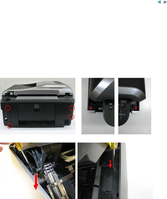
(1)External housing, ADF, and scanner unit removal
1)Remove the cassette, LAN connector cover, and telephone jack cover.
2)Remove the side covers L and R.
i.Remove 4 screws from the rear cover, and 1 screw each from the front left and front right.
ii. Release the hooks inside the cover.
20 / 65

iii. Release the boss on the front right and front left (beside the removed screws).
iv. Release the hooks on both sides of the rear tray.
21 / 65

3)Remove the front covers L and R.
i.Release one screw each from the top of the left and right front covers.
ii. Release the bosses on the top of the front covers.
22 / 65

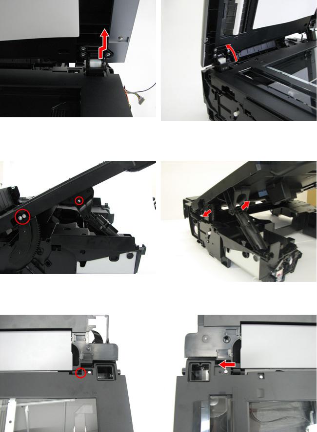
4)Remove the ADF unit, scanner unit, and main case all together.
i.Unlock the clear ink tank locking cover.
ii. Disconnect 4 connectors, and remove 3 screws.
iii. Remove 4 screws on the right side (2 each on the outer and inner sides of the machine), and disconnect 1 connector.
Use a short screwdriver to remove the screws from the inside of the machine. If a short screwdriver is not available, disengage the damper and open the scanning unit full while referring to step 6), "Remove the scanner unit."
23 / 65

iv. Remove 3 screws on the left side (1 each on the side, upper front, and upper back), and disconnect the connector.
v. Release the hooks, and insert a screwdriver between the gap so that the main case will not fall.
vi. Release the hook on the other side, and pull up the entire main case.
< With the main case removed >
24 / 65
5) Remove the ADF unit. (The ADF unit can be removed without removing the main case.)
i.Disengage the right hinge (while slightly pushing the hinge to the right, pull up the document cover).
ii. Disengage the left hinge (slowly lay back the document cover).
6) Remove the scanner unit. (The scanner unit can be removed without removing the main case.)
i.Remove 2 screws from the damper gear and 1 screw from the scanner lock.
ii. Disengage the damper gear and the scanner lock, while pushing them toward the arrow direction.
iii. While holding the scanner unit in the opened position, disengage the right hinge by slightly pushing the hinge to the right and pulling up the scanner unit.
iv. Disengage the left hinge by sliding the scanner unit to the left.
25 / 65

(2)Printer unit separation from the bottom case (how to remove the screw under the purge unit)
1)Rotate the purge unit gear toward the rear side of the machine to unlock the carriage.
2) Slide the carriage to the opposite of the home position (to the left), and remove the blade cleaner unit (2 screws).
3) Remove the screw under the blade cleaner unit.
26 / 65
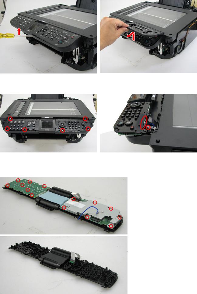
(3)Operation panel removal
1)Remove the panel cover.
Using a flat-blade screwdriver, release the front side of the panel cover.
While slightly lifting up the cover, pull it toward you.
2) Remove the panel unit.
Remove the 6 screws that fix the panel unit to the scanner unit. Pull the panel unit toward you, then disconnect the connector and the ground wire (1 screw).
3) Remove the panel board.
Remove the 14 screws and disconnect the connector.
Caution: DO NOT turn over the panel frame after the panel board is removed. The buttons are not fixed to the frame, thus they will fall if the frame is turned over.
27 / 65
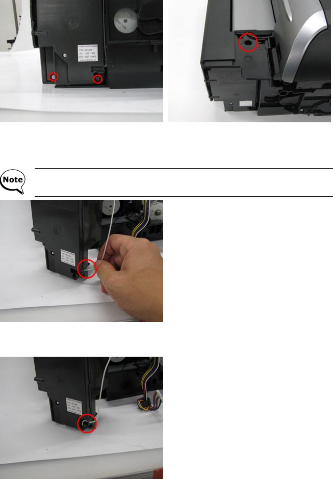
(4)AC adapter removal
1)Remove the side cover L.
2)Remove the AC adapter (2 screws on the side, 1 screw on the top).
Special notes on attaching the AC adapter:
< Japan model >
Insert and push the arrester ground wire in the hole until it fits to the arrester ground pin inside the AC adapter.
After connection, gently pull the ground wire and confirm that it will not be removed.
< Other models>
Fit the arrester ground wire in 2 grooves as shown in the photo.
28 / 65
 Loading...