


DCP-7055
Table of contents
 Loading...
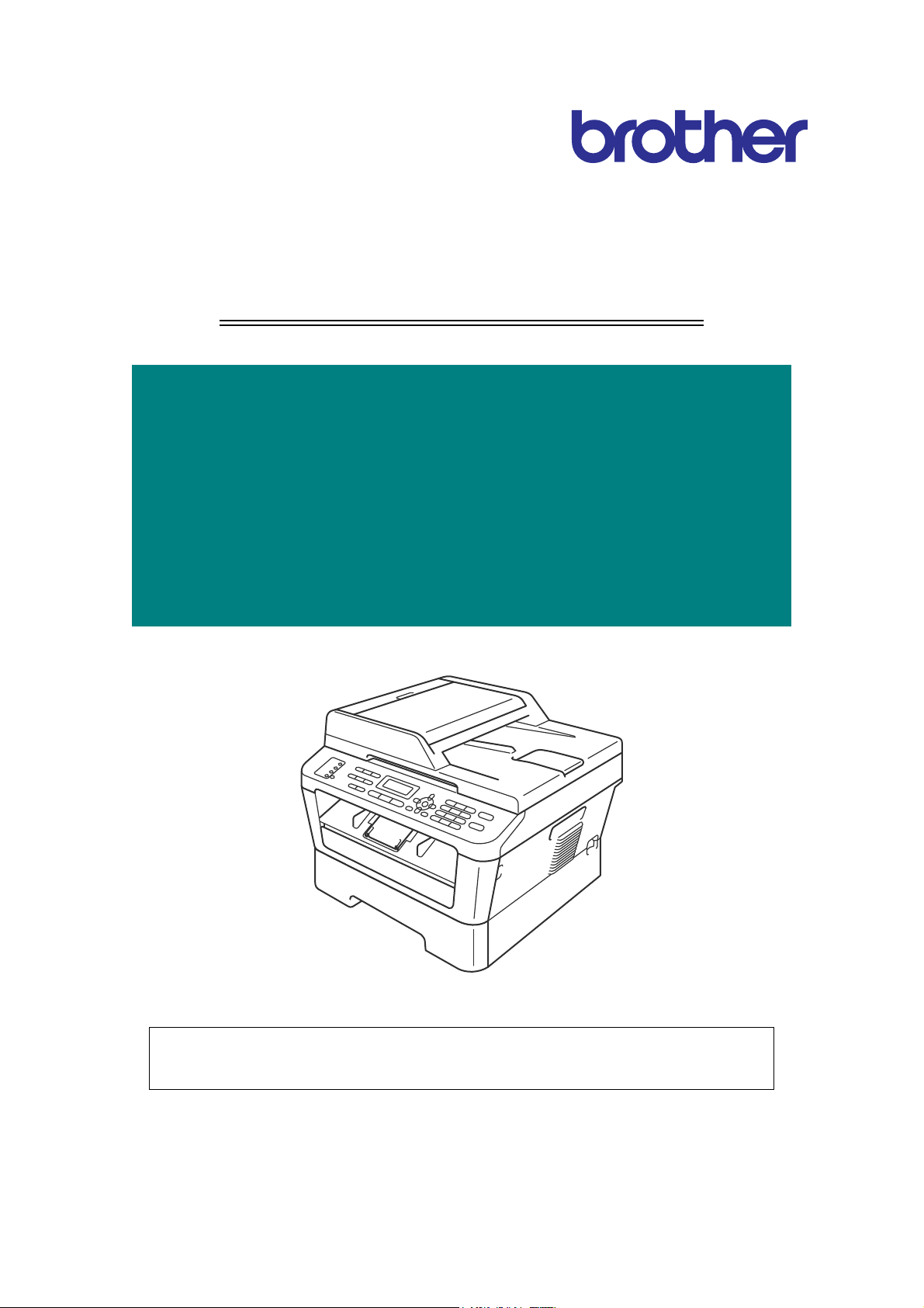
Confidential
Brother Laser MFC
SERVICE MANUAL
MODEL:
DCP- 7055/7055W/7057/7057E/7057W
DCP- 7060D/7065DN
DCP- 7070DW/HL-2280DW
MFC- 7360/7360N/7362N/7365DN/7460DN
MFC- 7470D/7860DN/7860DW
Read this manual thoroughly before maintenance work.
Keep this manual in a convenient place for quick and easy reference at all times.
December 2010
SM-FAX122
8C5E01 (9)

Confidential
TRADEMARKS
The Brother logo is a registered trademark of Brother Industries, Ltd.
Apple and Macintosh are trademarks of Apple Inc., registered in the United States and other countries.
PCL is either a trademark or a registered trademark of Hewlett-Packard Company in the United States
and other countries.
Windows Vista is either a registered trademark or a trademark of Microsoft Corporation in the United
States and/or other countries.
Microsoft, Windows, Windows Server and Internet Explorer are registered trademarks of Microsoft
Corporation in the United States and/or other countries.
Linux is a registered trademark of Linus Torvalds in the United States and other countries.
PostScript and PostScript3 are either registered trademarks or trademarks of Adobe Systems
Incorporated in the United States and/or other countries.
ENERGY STAR is a U.S. registered mark.
Citrix and MetaFrame are registered trademarks of Citrix Systems, Inc. in the United States.
Intel, Intel Xeon and Pentium are trademarks or registered trademarks of Intel Corporation.
AMD, AMD Athlon, AMD Opteron and combinations thereof, are trademarks of Advanced Micro
Devices, Inc.
PictBridge is a trademark.
Each company whose software title is mentioned in this manual has a Software License Agreement
specific to its proprietary programs.
All other trademarks are the property of their respective owners.
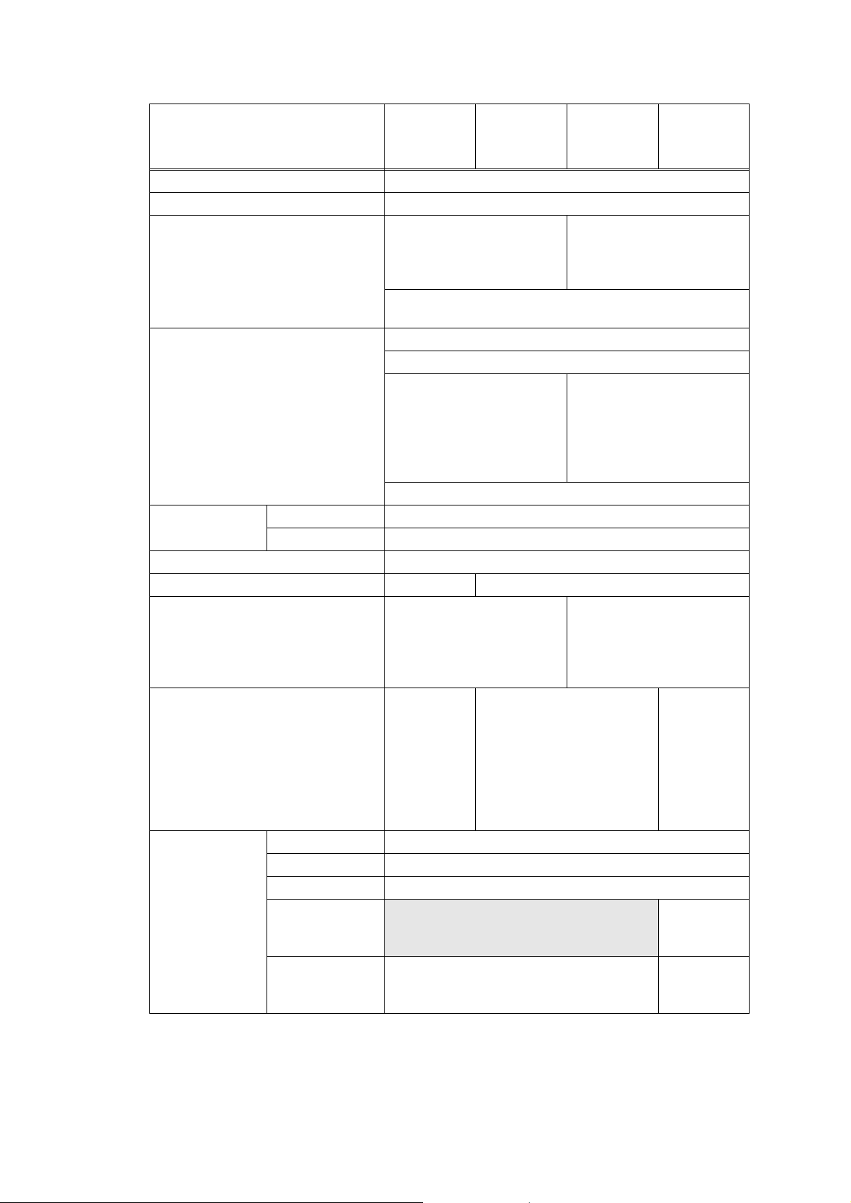
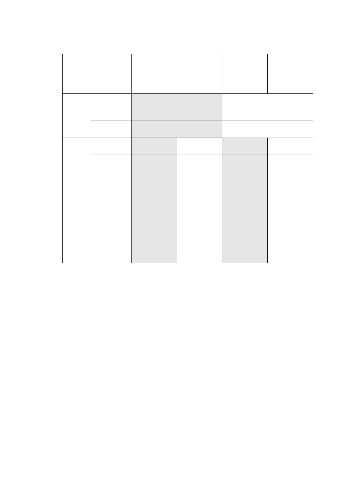
The function comparative table for models as described in this Service Manual are shown below.
© Copyright Brother 2010
All rights reserved.
No part of this publication may be reproduced in any form or by any means without permission in writing
from the publisher.
All other product and company names mentioned in this manual are trademarks or registered
trademarks of their respective holders.
Specifications are subject to change without notice.
Model
DCP-7055
DCP-7055W
DCP-7057W
DCP-7057
DCP-7057E
DCP-7060D
DCP-7065DN
DCP-7070DW
HL-2280DW
LAN
-
Wireless
--
Wired
Wired /
Wireless
Wired /
Wireless
Duplex printing
---
9
999
ADF
----
9
--
Handset
-------
Ten-key pad
-------
Paper Edge
Actuator
----
999
FAX
-------
Model MFC-7360
MFC-7360N
MFC-7362N
MFC-7365DN
MFC-7460DN
MFC-7470D MFC-7860DN MFC-7860DW
LAN
-
Wired Wired
-
Wired
Wired / Wireless
Duplex printing
--
9
999
ADF 999999
Handset
9
(Only for
China)
--
9
(For Asia &
China)
9
(Only for
China)
-
Ten-key pad 999999
Paper Edge
Actuator
--
9999
FAX 999999

i
Confidential
CONTENTS
REGULATION ..........................................................................................................vii
SAFETY INFORMATION .........................................................................................xiv
CHAPTER 1 SPECIFICATIONS
1. SPECIFICATIONS LIST ........................................................................................................... 1-1
1.1 General ............................................................................................................................... 1-1
1.2 Network Connectivity .......................................................................................................... 1-6
1.3 Service Information ............................................................................................................. 1-7
1.4 Consumables ...................................................................................................................... 1-8
1.5 Paper .................................................................................................................................. 1-9
1.5.1 Paper handling ....................................................................................................... 1-9
1.5.2 Media specifications ............................................................................................... 1-9
1.6 Unprintable Area ............................................................................................................... 1-10
1.7 Telephone ......................................................................................................................... 1-10
1.8 FAX ................................................................................................................................... 1-10
1.9 Copy ................................................................................................................................. 1-11
1.10 Scanner ............................................................................................................................ 1-11
1.11 Unscannable Area ............................................................................................................ 1-12
1.12 USB Direct Interface ......................................................................................................... 1-12
CHAPTER 2 ERROR INDICATION AND TROUBLESHOOTING
1. INTRODUCTION ...................................................................................................................... 2-1
1.1 Precautions ......................................................................................................................... 2-1
1.2 Initial Check ........................................................................................................................ 2-2
2. OVERVIEW .............................................................................................................................. 2-4
2.1 Cross-section Drawing ........................................................................................................ 2-4
2.2 Paper Feeding .................................................................................................................... 2-6
2.3 Operation of each part ........................................................................................................ 2-8
2.4 Block Diagram .................................................................................................................... 2-9
2.5 Components ..................................................................................................................... 2-10
2.6 Life of Toner Cartridge and Drum Unit .............................................................................. 2-11
3. ERROR CODES ..................................................................................................................... 2-15
3.1 Error Codes ...................................................................................................................... 2-15
3.2 Error Messages ................................................................................................................ 2-20
3.3 Communications Error Code ............................................................................................ 2-22
3.4 Error Cause and Remedy ................................................................................................. 2-25
3.5 Paper Feeding Problems .................................................................................................. 2-71

ii
Confidential
3.5.1 Pickup function of Paper tray does not work. ....................................................... 2-71
3.5.2 No feeding ............................................................................................................ 2-71
3.5.3 No paper fed manual feed slot (Error code 9A) .................................................... 2-72
3.5.4 Double feeding ..................................................................................................... 2-72
3.5.5 Paper jam ............................................................................................................. 2-73
3.5.6 Dirt on paper ......................................................................................................... 2-75
3.5.7 Paper feeding at an angle .................................................................................... 2-75
3.5.8 Wrinkles or creases .............................................................................................. 2-76
3.5.9 Curl in the paper ................................................................................................... 2-77
3.5.10 Prints only single side of the paper when duplex-printing .................................... 2-78
3.5.11 Cannot make print through duplex-printing .......................................................... 2-78
3.5.12 Paper size error .................................................................................................... 2-78
3.5.13 Paper size error through duplex-printing .............................................................. 2-78
3.6 Image Defect Troubleshooting .......................................................................................... 2-79
3.6.1 Image defect examples ........................................................................................ 2-79
3.6.2 Troubleshooting image defect .............................................................................. 2-80
3.7 Software Setting Problems ............................................................................................... 2-91
3.7.1 Cannot print data .................................................................................................. 2-91
3.8 Network Problems ............................................................................................................ 2-92
3.8.1 Cannot make a print through network connection
(Wireless LAN model only) (Error code DE, EE) .................................................. 2-92
3.9 Document Feeding Problems ........................................................................................... 2-93
3.9.1 No feeding ............................................................................................................ 2-93
3.9.2 Double feeding ..................................................................................................... 2-93
3.9.3 Paper jam ............................................................................................................. 2-94
3.9.4 Wrinkles ................................................................................................................ 2-95
3.10 Scanning Image Defect Troubleshooting .......................................................................... 2-96
3.10.1 Image defect examples ........................................................................................ 2-96
3.10.2 Troubleshooting image defect .............................................................................. 2-96
3.11 Troubleshooting of the Control Panel ............................................................................... 2-99
3.11.1 Nothing is displayed on the LCD .......................................................................... 2-99
3.11.2 The control panel does not work .......................................................................... 2-99
3.11.3 Lamp malfunction ................................................................................................. 2-99
3.12 Troubleshooting of FAX/Telephone Functions ............................................................... 2-100
3.12.1 FAX can't send it ................................................................................................ 2-100
3.12.2 FAX cannot be transmitted and received ........................................................... 2-100
3.12.3 No bell ring ......................................................................................................... 2-100
3.12.4 A communication error occurs ............................................................................ 2-101
3.12.5 Reception mode cannot be changed .................................................................. 2-101
3.12.6 Caller ID are not displayed ................................................................................. 2-101
3.12.7 Cannot talk on the handset ................................................................................ 2-101
3.13 PCB Problems ................................................................................................................ 2-102
3.13.1 Main PCB failure ................................................................................................ 2-102
3.13.2 Out of Memory .................................................................................................... 2-102
3.13.3 High voltage power supply PCB ASSY failure ................................................... 2-102

iii
Confidential
3.13.4 Low voltage power supply PCB ASSY failure .................................................... 2-103
3.13.5 NCU ASSY failure .............................................................................................. 2-103
3.14 Other Problems ............................................................................................................... 2-104
3.14.1 The machine is not turned ON, or the LCD indication does not appear ............. 2-104
3.14.2 Fuser fan does not rotate ................................................................................... 2-104
3.14.3 The room temperature is high or low .................................................................. 2-104
3.14.4 Problem associated with Secure Function Lock ................................................ 2-104
CHAPTER 3 DISASSEMBLY/REASSEMBLY
1. SAFETY PRECAUTIONS ........................................................................................................ 3-1
2. PACKING ................................................................................................................................. 3-2
3. SCREW CATALOGUE ............................................................................................................. 3-3
4. SCREW TORQUE LIST ........................................................................................................... 3-4
5. LUBRICATION ......................................................................................................................... 3-6
6. OVERVIEW OF GEARS ........................................................................................................... 3-7
7. HARNESS ROUTING ............................................................................................................. 3-10
8. DISASSEMBLY FLOW CHART ............................................................................................. 3-26
9. DISASSEMBLY PROCEDURE .............................................................................................. 3-27
9.1 Paper Tray ........................................................................................................................ 3-29
9.2 Cord Hook ......................................................................................................................... 3-32
9.3 Back Cover ....................................................................................................................... 3-33
9.4 Outer Chute ASSY ............................................................................................................ 3-34
9.5 Fuser Cover ...................................................................................................................... 3-35
9.6 Inner Chute ASSY, Eject Pinch Roller R ASSY and Eject Pinch Roller L ASSY .............. 3-36
9.7 Front Cover ASSY, Support Flap 1 ................................................................................... 3-38
9.8 Side cover L / Handset holder ASSY ................................................................................ 3-40
9.9 Side Cover R .................................................................................................................... 3-43
9.10 ADF Unit (For models with ADF) ...................................................................................... 3-44
9.10.1 ADF Unit ............................................................................................................... 3-44
9.10.2 Hinge ASSY L / Hinge Arm R / Hinge R / Hinge R support .................................. 3-46
9.10.3 Document Stopper ............................................................................................... 3-47
9.10.4 Document Sub Tray ............................................................................................. 3-48
9.10.5 ADF Cover ASSY ................................................................................................. 3-49
9.10.6 Gear Cover ........................................................................................................... 3-50
9.10.7 Separation Roller ASSY ....................................................................................... 3-51
9.10.8 Separation Rubber Holder ASSY ......................................................................... 3-52
9.10.9 Upper Document Chute ASSY SX ....................................................................... 3-53
9.10.10Document Feed Roller ASSY ............................................................................... 3-54
9.10.11Lower Document Chute ASSY ............................................................................. 3-55
9.10.12Ejection Roller ASSY ............................................................................................ 3-56
9.10.13ADF motor ............................................................................................................ 3-57

iv
Confidential
9.10.14Document Scanning Position Detection Sensor PCB ASSY/
Document Detection/ADF Cover Open Sensor PCB ASSY ................................. 3-59
9.11 Document Cover ASSY (For models without ADF) .......................................................... 3-61
9.12 Pull Arm L / Pull Arm R / Pull Arm Spring ......................................................................... 3-63
9.13 Document Scanner Unit .................................................................................................... 3-66
9.14 Panel Unit ......................................................................................................................... 3-67
9.14.1 Panel Unit ............................................................................................................. 3-67
9.14.2 Panel PCB ASSY ................................................................................................. 3-68
9.14.3 Rubber Key L/R .................................................................................................... 3-69
9.14.4 LCD ...................................................................................................................... 3-70
9.15 CIS unit ............................................................................................................................. 3-71
9.16 Pull Arm Guide .................................................................................................................. 3-73
9.17 NCU ASSY ....................................................................................................................... 3-74
9.18 Speaker Unit ..................................................................................................................... 3-78
9.19 Joint cover ........................................................................................................................ 3-80
9.20 Fuser Unit ......................................................................................................................... 3-82
9.21 Low voltage power supply PCB ASSY ............................................................................. 3-85
9.22 Fuser Fan ......................................................................................................................... 3-88
9.23 High Voltage Power Supply PCB ASSY ........................................................................... 3-89
9.24 New Toner Sensor PCB ASSY ......................................................................................... 3-90
9.25 Filter .................................................................................................................................. 3-91
9.26 Laser Unit ......................................................................................................................... 3-92
9.27 Wireless LAN PCB ASSY (Wireless LAN model only) ..................................................... 3-94
9.28 Pick-up Roller Holder ASSY ............................................................................................. 3-95
9.29 Rubber Foot ...................................................................................................................... 3-96
9.30 Main PCB ASSY ............................................................................................................... 3-97
9.31 T1 Clutch ASSY, REG Clutch ASSY ................................................................................ 3-98
9.32 Main Frame L ASSY ....................................................................................................... 3-100
9.33 Develop Drive Sub ASSY, Develop Gear Joint/52 ......................................................... 3-102
9.34 Motor Drive Sub ASSY, Main Motor ............................................................................... 3-104
9.35 Internal Temperature Sensor .......................................................................................... 3-106
9.36 Paper Eject Sensor PCB ASSY ...................................................................................... 3-107
9.37 Fuser Gear 28/34 ............................................................................................................ 3-109
CHAPTER 4 ADJUSTMENTS AND UPDATING OF SETTINGS,
REQUIRED AFTER PARTS REPLACEMENT
1. IF YOU REPLACE THE MAIN PCB ASSY .............................................................................. 4-1
1.1 Rewriting the firmware (Sub firmware, Main firmware) ....................................................... 4-2
1.1.1 Checking firmware version ..................................................................................... 4-2
1.1.2 Rewriting the firmware using computer .................................................................. 4-2
1.2 Initialization of EEPROM of Main PCB ASSY (Maintenance Mode: Code 01) ................... 4-3
1.3 Setting by Country (Maintenance Mode: Code 74) ............................................................. 4-3
1.4 Setting the Serial Number ................................................................................................... 4-3

v
Confidential
1.5 Inputting the Adjusted Value of the Laser Unit ................................................................... 4-5
1.6 Acquisition of White Level Data (Maintenance Mode: Code 55) ........................................ 4-9
1.7 Operation Check of Sensors (Maintenance Mode: Code 32) ............................................. 4-9
2. IF YOU REPLACE THE LASER UNIT ................................................................................... 4-10
2.1 Inputting the Adjusted Value of the Laser Unit ................................................................. 4-10
3. IF YOU REPLACE THE LOW VOLTAGE POWER SUPPLY PCB ASSY ............................ 4-14
3.1 Reset of Irregular Power Supply Detection Counter ......................................................... 4-14
4. IF YOU REPLACE THE DOCUMENT SCANNER UNIT / THE CIS UNIT ............................. 4-15
4.1 Acquisition of White Level Data (Maintenance Mode: Code 55) ...................................... 4-15
4.2 Scanning and Printing Check ........................................................................................... 4-15
4.3
Placement of Scanner Unit in Position for Transportation (Maintenance Mode: Code 06)
. 4-15
5. IF YOU REPLACE THE PANEL UNIT ................................................................................... 4-15
5.1 Operation Check of LCD (Maintenance Mode: Code 12) ................................................. 4-15
5.2 Operation Check of Control Panel Button (Maintenance Mode: Code 13) ....................... 4-15
6. IF YOU REPLACE THE LCD UNIT ........................................................................................ 4-16
6.1 Operation Check of LCD (Maintenance Mode: Code 12) ................................................. 4-16
CHAPTER 5 SERVICE FUNCTIONS
1. MAINTENANCE MODE ........................................................................................................... 5-1
1.1 How to Enter the Maintenance Mode ................................................................................. 5-1
1.2 How to Enter the End User-accessible Maintenance Mode ............................................... 5-1
1.3 List of Maintenance-mode Functions .................................................................................. 5-2
1.4 Detailed Description of Maintenance-mode Functions ....................................................... 5-3
1.4.1 EEPROM parameter initialization (Function code 01, 91) ...................................... 5-3
1.4.2 Printout of scanning compensation data (Function code 05) ................................. 5-4
1.4.3 Placement of scanner unit in position for transportation (Function code 06) ......... 5-6
1.4.4 ADF performance test (Function code 08) ............................................................. 5-6
1.4.5 Monochrome image quality test pattern (Function code 09) .................................. 5-7
1.4.6 Worker switch (WSW) setting and printout (Function code 10, 11) ........................ 5-8
1.4.7 Operational check of LCD (Function code 12) ..................................................... 5-12
1.4.8 Operational check of control panel button (Function code 13) ............................. 5-13
1.4.9 Software version check (Function code 25) ......................................................... 5-14
1.4.10 Operational check of sensors (Function code 32) ................................................ 5-15
1.4.11 LAN connection status display (Function code 33) .............................................. 5-17
1.4.12 PC print function (Function code 43) .................................................................... 5-18
1.4.13 Not-disclosed-to-users functions (Function code 45) ........................................... 5-21
1.4.14 EEPROM customizing (User-accessible) (Function code 52) .............................. 5-22
1.4.15 Received data transfer function (Function code 53) (FAX model only) ................ 5-23
1.4.16 Fine adjustment of scan start/end positions (Function code 54) .......................... 5-25
1.4.17 Acquisition of white level data (Function code 55) ............................................... 5-26
1.4.18 Continuous print test (Function code 67) ............................................................. 5-27
1.4.19 Setting by country (Function code 74) .................................................................. 5-28
1.4.20 Printout of maintenance information (Function code 77) ...................................... 5-31

vi
Confidential
1.4.21 Operational check of fan (Function code 78) ....................................................... 5-32
1.4.22 Display of the machine history (log) (Function code 80) ...................................... 5-33
1.4.23 Error code indication (Function code 82) ............................................................. 5-37
1.4.24 Sending communication error list (Function code 87) (FAX model only) ............. 5-37
1.4.25 Counter reset after replacing the fuser unit and paper feeding kit
(Function code 88) ............................................................................................... 5-38
1.4.26 Exit from the maintenance mode (Function code 99) ........................................... 5-38
2. OTHER SERVICE FUNCTIONS ............................................................................................ 5-39
2.1 Developer Roller Counter Reset Function ........................................................................ 5-39
2.2 Parts Life Reset Function ................................................................................................. 5-40
2.3 Deletion of User Setting Information, etc. ......................................................................... 5-40
2.4 Continue mode / Stop mode settings of Toner cartridge .................................................. 5-41
2.5 Drum Cleaning .................................................................................................................. 5-41
2.6 ON/OFF Setting of Deep Sleep Function ......................................................................... 5-42
CHAPTER 6 CIRCUIT DIAGRAMS, WIRING DIAGRAM
1. CIRCUIT DIAGRAMS ............................................................................................................... 6-1
2. WIRING DIAGRAM ................................................................................................................ 6-10
CHAPTER 7 PERIODICAL MAINTENANCE
1. PERIODICAL REPLACEMENT PARTS .................................................................................. 7-1
APPENDIX 1 SERIAL NUMBERING SYSTEM
APPENDIX 2 DELETION OF USER SETTING INFORMATION, ETC.
APPENDIX 3 INSTALLING THE MAINTENANCE DRIVER
APPENDIX 4 HOW TO MAKE PROTECTIVE MATERIAL OF DRUM UNIT

vii
Confidential
REGULATION
Approval Information (MFC only)
THIS EQUIPMENT IS DESIGNED TO WORK WITH A TWO WIRE ANALOGUE PSTN LINE
FITTED WITH THE APPROPRIATE CONNECTOR.
Brother advises that this product may not function correctly in a country other than where it
was originally purchased, and does not offer any warranty in the event that this product is
used on public telecommunication lines in another country.
Declaration of Conformity (Europe only)
(DCP-7055/DCP-7057/DCP-7057E/DCP-7060D/DCP-7065DN/MFC-7360/
MFC-7362N/MFC-7360N/MFC-7460DN/MFC-7470D/MFC-7860DN only)
We, Brother Industries, Ltd.
15-1, Naeshiro-cho, Mizuho-ku, Nagoya 467-8561 Japan
declare that this product is in compliance with the essential requirements of Directives
2004/108/EC, 2006/95/EC and 2005/32/EC.
The Declaration of Conformity (DoC) is on our Website.
Please go to http://solutions.brother.com/.
• choose region (eg. Europe)
• choose country
• choose your model
• choose “Manuals”
• choose Declaration of Conformity (Select Language when required.)
Declaration of Conformity (Europe only)
(DCP-7055W/DCP-7057W/DCP-7070DW/MFC-7860DW only)
We, Brother Industries, Ltd.
15-1, Naeshiro-cho, Mizuho-ku, Nagoya 467-8561 Japan
declare that this product is in compliance with the essential requirements of Directives
1999/5/EC and 2005/32/EC.
The Declaration of Conformity (DoC) is on our Website.
Please go to http://solutions.brother.com/.
• choose region (eg. Europe)
• choose country
• choose your model
• choose “Manuals”
• choose Declaration of Conformity (Select Language when required.)
viii
Confidential
IEC60825-1:2007 Specification (For 220-240V models only)
This product is a Class 1 laser product as defined in IEC60825-1:2007 specifications.
The label shown below is attached in countries where required.
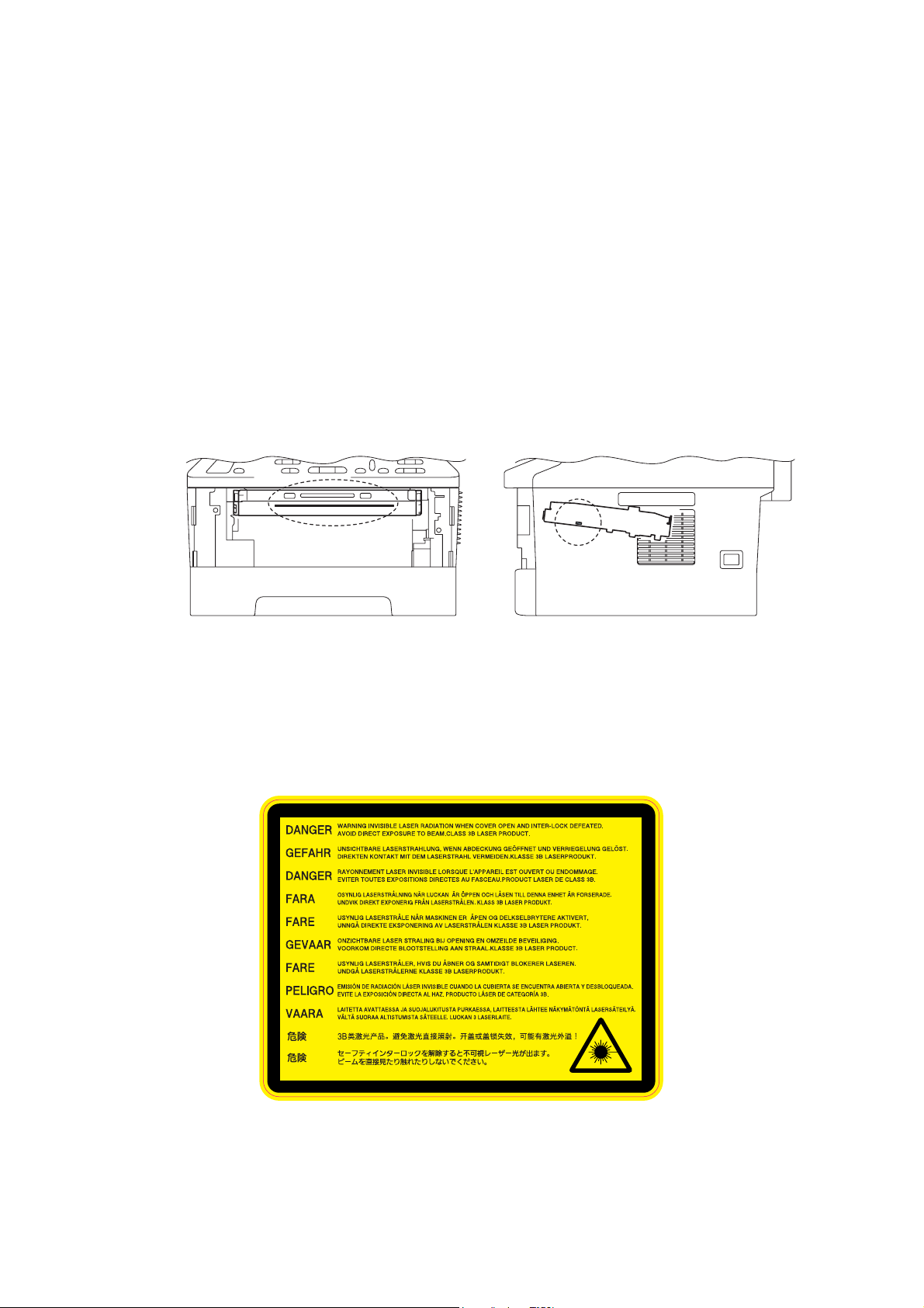
This product has a Class 3B Laser Diode which emits invisible laser radiation in the scanner
unit. The scanner unit should not be opened under any circumstances.
Internal laser radiation
Wave length: 770 - 800 nm
Output: 25 mW max.
Laser Class: Class 3B
Disconnect Device
This product must be installed near an electrical socket that is easily accessible. In case of
emergencies, you must disconnect the power cord from the electrical socket to shut off
power completely.
Wiring Information (U.K. only)
If you need to replace the plug fuse, fit a fuse that is approved by ASTA to BS1362 with the
same rating as the original fuse.
Always replace the fuse cover. Never use a plug that does not have a cover. If in any doubt,
call a qualified electrician.
Warning -This product must be earthed.
The wires in the mains lead are coloured in line with the following code:
• Green and Yellow: Earth
• Blue: Neutral
•Brown: Live
LAN Connection (Network models only)
WARNING
Use of controls, adjustments or performance of procedures other than those specified
in this manual may result in hazardous radiation exposure.
CAUTION
DO NOT connect this product to a LAN connection that is subject to over-voltages.
CLASS 1 LASER PRODUCT
APPAREIL À LASER DE CLASSE 1
LASER KLASSE 1 PRODUKT

ix
Confidential
Radio Interference
This product complies with EN55022 (CISPR Publication 22)/Class B.
EU Directive 2002/96/EC and EN50419
This equipment is marked with the above recycling symbol. It means that at the end of the life
of the equipment you must dispose of it separately at an appropriate collection point and not
place it in the normal domestic unsorted waste stream. This will benefit the environment for
all. (European Union only)

x
Confidential
For USA and Canada
Standard telephone and FCC notices (MFC only)
These notices are in effect on models sold and used in the United States only.
When programming emergency numbers or making test calls to emergency numbers:
• Remain on the line and briefly explain to the dispatcher the reason for the call before
hanging up.
• Perform these activities in the off-peak hours, such as early morning or late evening.
This equipment complies with Part 68 of the FCC rules and the requirements adopted by the
ACTA. On the backside of this equipment is a label that contains, among other information, a
product identifier in the format US: AAAEQ##TXXXX. If requested, this number must be
provided to the telephone company.
You may safely connect this equipment to the telephone line by means of a standard modular
jack, USOC RJ11C.
A plug and jack used to connect this equipment to the premises wiring and telephone
network must comply with the applicable FCC Part 68 rules and requirements adopted by the
ACTA. A compliant telephone cord and modular plug is provided with this product. It is
designed to be connected to a compatible modular jack that is also compliant. (See
installation instructions for details.)
The REN is used to determine the number of devices that may be connected to a telephone
line. Excessive RENs on a telephone line may result in the devices not ringing in response to
an incoming call. In most but not all areas, the sum of RENs should not exceed five (5.0). To
be certain of the number of devices that may be connected to a line, as determined by the
total RENs, contact the local telephone company. For products approved after July 23, 2001,
the REN for this product is part of the product identifier that has the format
US:AAAEQ##TXXXX. The digits represented by ## are the REN without a decimal point
(e.g., 06 is a REN of 0.6). For earlier products, the REN is separately shown on the label.
If this equipment causes harm to the telephone network, the telephone company will notify
you in advance that temporary discontinuance of service may be required. But if advance
notice is not practical, the telephone company will notify the customer as soon as possible.
Also, you will be advised of your right to file a complaint with the FCC if you believe it is
necessary.
The telephone company may make changes in its facilities, equipment, operations or
procedures that could affect the operation of the equipment. If this happens the telephone
company will provide advance notice in order for you to make necessary modifications to
maintain uninterrupted service.
If trouble is experienced with this equipment, for repair or warranty information, please
contact Brother Customer Service. (See Brother numbers in the Basic User's Guide.) If the
equipment is causing harm to the telephone network, the telephone company may request
that you disconnect the equipment until the problem is resolved.
Connection to party line service is subject to state tariffs. Contact the state public utility
commission, public service commission or corporation commission for information.
If your home has specially wired alarm equipment connected to the telephone line, ensure
the installation of this equipment does not disable your alarm equipment. If you have
questions about what will disable alarm equipment, call your telephone company or a
qualified installer.
If you are not able to solve a problem with your product, call Brother Customer Service. (See
Brother numbers in the Basic User's Guide.)
WARNING
For protection against the risk of electrical shock, always disconnect all cables from
the wall outlet before servicing, modifying or installing the equipment.

xi
Confidential
Federal Communications Commission (FCC) Declaration of Conformity
(For USA)
Responsible Party: Brother International Corporation
100 Somerset Corporate Boulevard
P. O . B o x 6 9 11
Bridgewater, NJ 08807-0911
USA
Telephone: (908) 704-1700
declares, that the products
Product name: DCP-7060D/DCP-7065DN/HL-2280DW/
MFC-7360N/MFC-7365DN/MFC-7460DN/MFC-7860DW
complies with Part 15 of the FCC Rules. Operation is subject to the following two conditions:
(1) This device may not cause harmful interference, and (2) this device must accept any
interference received, including interference that may cause undesired operation.
This equipment has been tested and found to comply with the limits for a Class B digital
device, pursuant to Part 15 of the FCC Rules. These limits are designed to provide
reasonable protection against harmful interference in a residential installation. This
equipment generates, uses, and can radiate radio frequency energy and, if not installed and
used in accordance with the instructions, may cause harmful interference to radio
communications. However, there is no guarantee that interference will not occur in a
particular installation. If this equipment does cause harmful interference to radio or television
reception, which can be determined by turning the equipment off and on, the user is
encouraged to try to correct the interference by one or more of the following measures:
• Reorient or relocate the receiving antenna.
• Increase the separation between the equipment and receiver.
• Connect the equipment into an outlet on a circuit different from that to which the receiver is
connected.
• Consult the dealer or an experienced radio/TV technician for help.
(Wireless network models only)
This transmitter must be co-located or operated in conjunction with any other antenna or
transmitter.
Important
A shielded interface cable should be used to ensure compliance with the limits for a Class B
digital device. Changes or modifications not expressly approved by Brother Industries, Ltd.
could void the user’s authority to operate the equipment.

xii
Confidential
Industry Canada Compliance Statement (For Canada)
This Class B digital apparatus complies with Canadian ICES–003.
Cet appareil numérique de la classe B est conforme à la norme NMB–003 du Canada.
Operation is subject to the following two conditions: (1) this device may not cause
interference, and (2) this device must accept any interference, including interference that
may cause undesired operation of this device.
L’utilisation de ce dispositif est autorisée seulement aux conditions suivantes:
(1) il ne doit pas produire de brouillage et (2) l’utilisateur du dispositif doit être prêt à accepter
tout brouillage radioélectrique reçu, même si ce brouillage est susceptible de compromettre
le fonctionnement du dispositif.
Equipment Attachment Limitations (Canada only)
(MFC only)
NOTICE
This product meets the applicable Industry Canada technical specifications.
Le présent materiel est conforme aux specifications techniques applicables d’Industrie
Canada.
NOTICE
The Ringer Equivalence Number is an indication of the maximum number of devices allowed
to be connected to a telephone interface. The termination on an interface may consist of any
combination of devices subject only to the requirement that the sum of the RENs of all the
devices does not exceed five.
L’indice d’équivalence de la sonnerie (IES) sert à indiquer le nombre maximal de terminaux
qui peuvent être raccordés à une interface téléphonique. La terminaison d’une interface peut
consister en une combinaison quelconque de dispositifs, à la seule condition que la somme
d’indices d’équivalence de la sonnerie de tous les dispositifs n’excède pas 5.
Laser Safety (110 to 120 volt model only)
This machine is certified as a Class 1 laser product under the USA. Department of Health
and Human Services (DHHS) Radiation Performance Standard according to the Radiation
Control for Health and Safety Act of 1968. This means that the machine does not produce
hazardous laser radiation.
Since radiation emitted inside the machine is completely confined within protective housings
and external covers, the laser beam cannot escape from the machine during any phase of
user operation.

xiii
Confidential
FDA Regulations (110 to 120 volt model only)
The USA Food and Drug Administration (FDA) has implemented regulations for laser
products manufactured on and after August 2, 1976. Compliance is mandatory for products
marketed in the United States. The following label on the back of the machine indicates
compliance with the FDA regulations and must be attached to laser products marketed in the
United States.
Internal laser radiation
Maximum radiation power: 25 mW
Wave length: 770 - 800 nm
Laser class: Class 3B
MANUFACTURED:
BROTHER INDUSTRIES (VIETNAM) LTD.
Phuc Dien Industrial Zone Cam Phuc Commune, Cam giang Dist Hai Duong Province,
Vietnam.
This product complies with FDA performance standards for laser products except for
deviations pursuant to Laser Notice No. 50, dated June 24, 2007.
MANUFACTURED:
Brother Technology (Shenzhen) Ltd.
NO6 Gold Garden Ind., Nanling Nanwan, Longgang, Shenzhen, China
This product complies with FDA performance standards for laser products except for
deviations pursuant to Laser Notice No.50, dated Jun 24, 2007.
xiv
Confidential
SAFETY INFORMATION
Caution for Laser Product (WARNHINWEIS fur Laser drucker)
CAUTION: When the machine during servicing is operated with the cover open, the
regulations of VBG 93 and the performance instructions for VBG 93 are
valid.
CAUTION: In case of any trouble with the laser unit, replace the laser unit itself. To
prevent direct exposure to the laser beam, do not try to open the enclosure
of the laser unit.
ACHTUNG: Im Falle von Störungen der Lasereinheit muß diese ersetzt werden. Das
Gehäuse der Lasereinheit darf nicht geöffnet werden, da sonst
Laserstrahlen austreten können.
Additional Information
When servicing the optical system of the machine, be careful not to place a screwdriver or
other reflective object in the path of the laser beam. Be sure to take off any personal
accessories such as watches and rings before working on the machine. A reflected beam,
though invisible, can permanently damage the eyes.
Since the beam is invisible, the following caution label is attached on the laser unit.
<Location of the laser beam window>
xv
Confidential
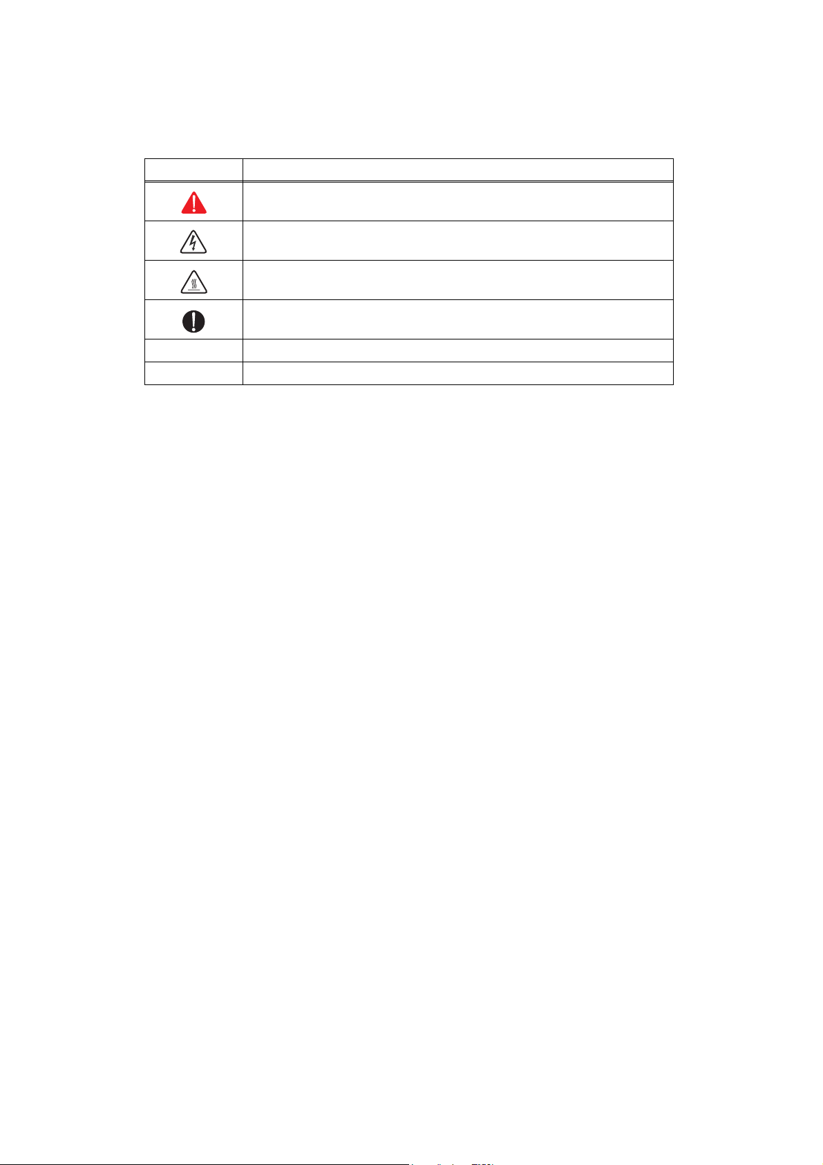
Definitions of Warnings, Cautions, Notes and Memos
The following conventions are used in this manual:
Mark Contents
Warnings tell you what to do to prevent possible personal injury.
Electrical Hazard icons alert you to a possible electrical shock.
Hot Surface icons warn you not to touch machine parts that are hot.
Cautions specify procedures you must follow or avoid to prevent
possible damage to the machine or other objects.
Note Notes tell you useful tips when servicing the machine.
Memo Memo tells you bits of knowledge to help understand the machine.

xvi
Confidential
Safety Precautions
Listed below are the various kinds of “WARNING” messages included in this manual.
WARNING
There are high voltage electrodes inside the machine. Before you clean the inside of
the machine or replace parts, make sure that you have turned off the power switch
and unplugged the machine from the AC power outlet.
DO NOT handle the plug with wet hands. Doing this might cause an electrical shock.
The fuser unit becomes extremely hot during operation. Wait until it has cooled down
sufficiently before replacing consumable items. DO NOT remove or damage the
caution label located on or around the fuser.
xvii
Confidential
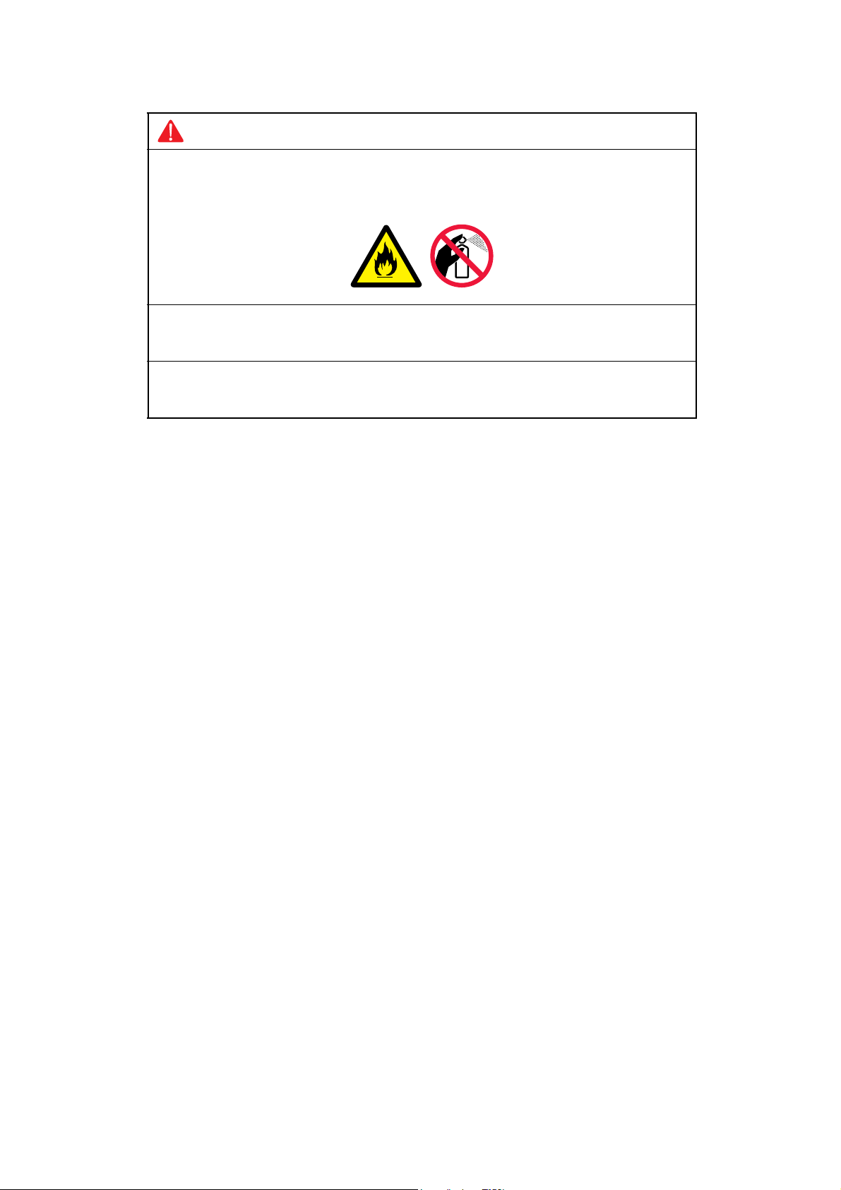
WARNING
DO NOT use flammable substances such as alcohol, benzine, thinner or any type of
spray to clean the inside or outside of the machine. Doing this may cause a fire or
electrical shock.
If the machine becomes hot, blows smoke, or generates obscure odor, immediately
turn off the power switch and unplug the machine from the AC power outlet.
If metal objects, water or other liquids get inside the machine, immediately turn off the
power switch and unplug the machine from the AC power outlet.
xviii
Confidential
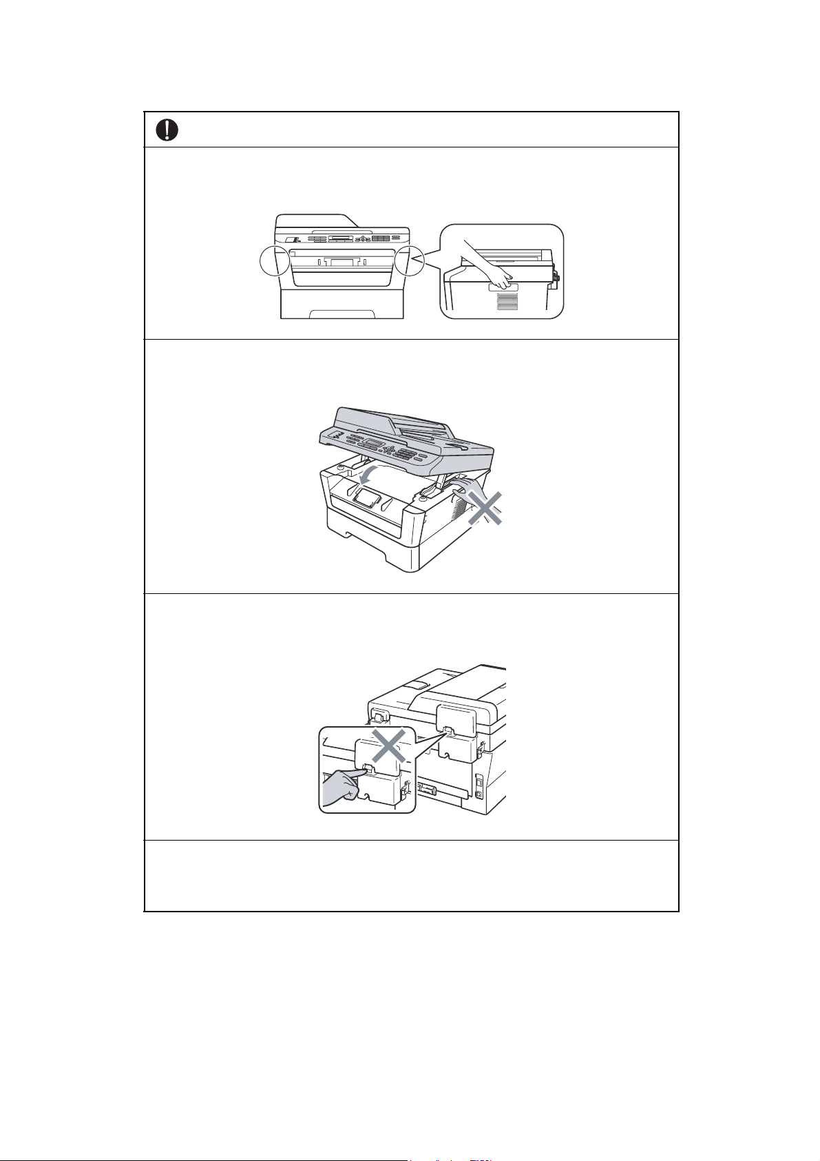
CAUTION
When you move the machine, grasp the side handholds that are under the scanner.
DO NOT carry the machine by holding it at the bottom.
To prevent injuries, be careful not to put your hands on the edge of the product under
the scanner as shown in the illustrations.
To prevent injuries, be careful not to put your fingers in the areas shown in the
illustrations.
Lightning and power surges can damage this product! We recommend that you use a
quality surge protection device on the AC power line, or unplug the machine during a
lightning storm.

CHAPTER 1
SPECIFICATIONS

Confidential
CHAPTER 1 SPECIFICATIONS
This chapter lists the specifications of each model.
CONTENTS
1. SPECIFICATIONS LIST................................................................................................1-1
1.1 General.................................................................................................................. 1-1
1.2 Network Connectivity.............................................................................................1-6
1.3 Service Information................................................................................................1-7
1.4 Consumables......................................................................................................... 1-8
1.5 Paper .....................................................................................................................1-9
1.5.1 Paper handling ........................................................................................... 1-9
1.5.2 Media specifications ................................................................................... 1-9
1.6 Unprintable Area.................................................................................................. 1-10
1.7 Telephone ............................................................................................................ 1-10
1.8 FAX...................................................................................................................... 1-10
1.9 Copy .................................................................................................................... 1-11
1.10 Scanner ............................................................................................................... 1-11
1.11 Unscannable Area ............................................................................................... 1-12
1.12 USB Direct Interface............................................................................................ 1-12
1-1
Confidential
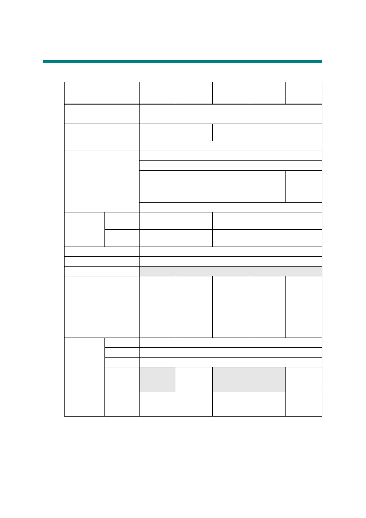
1. SPECIFICATIONS LIST
1.1 General
Specifications are subject to change without notice.
Model
DCP-7055
DCP-7057
DCP-7057E
DCP-7055W
DCP-7057W
DCP-7060D DCP-7065DN
DCP-7070DW
HL-2280DW
Print method Electrophotographic / Laser
Resolution 600 dpi x 600 dpi, HQ1200 (2400 X 600 dpi) quality
Print speed Up to 20/21 ppm Up to 24/24
ppm
Up to 26/27 ppm
* When loading A4 or Letter-size paper from the paper tray.
Warm-up time From Sleep Mode: Less than 7 seconds
* At 23°C (73.4F)
From Power OFF → ON: Less than 27 seconds From Power
OFF → ON:
Less than
28 seconds
* At 23°C (73.4F)
First print
time
From Ready
mode
Less than 10.0 seconds Less than 8.5 seconds
From Sleep
mode
Less than 19.0 seconds Less than 16.5 seconds
CPU ARM9 200MHz
Memory 16 MB 32 MB
Backup Clock
N/A
Interface Hi-Speed
USB 2.0
Hi-Speed USB
2.0,
IEEE802.11b/g
(Infrastructure
Mode / Adhoc
Mode)
Hi-Speed
USB 2.0
Hi-Speed
USB 2.0,
Ethernet 10/
100 BASE-
TX
Hi-Speed USB
2.0, Ethernet
10/100 BASE-
TX,
IEEE802.11b/g
(Infrastructure
Mode / Adhoc
Mode)
Power
Consumption
* Measured
with only
USB
connected
Peak 1080 W
Copying Average: Approximately 445 W
Ready Average: Approximately 55 W
Sleep,
Wireless
LAN: ON
N/A
Average:
Approximately
2.8 W
N/A
Average:
Approximately
2.8 W
Deep Sleep
Average:
Approximately
0.9 W
Average:
Approximately
1.0 W
Average: Approximately
0.9 W
Average:
Approximately
1.0 W
1-2
Confidential
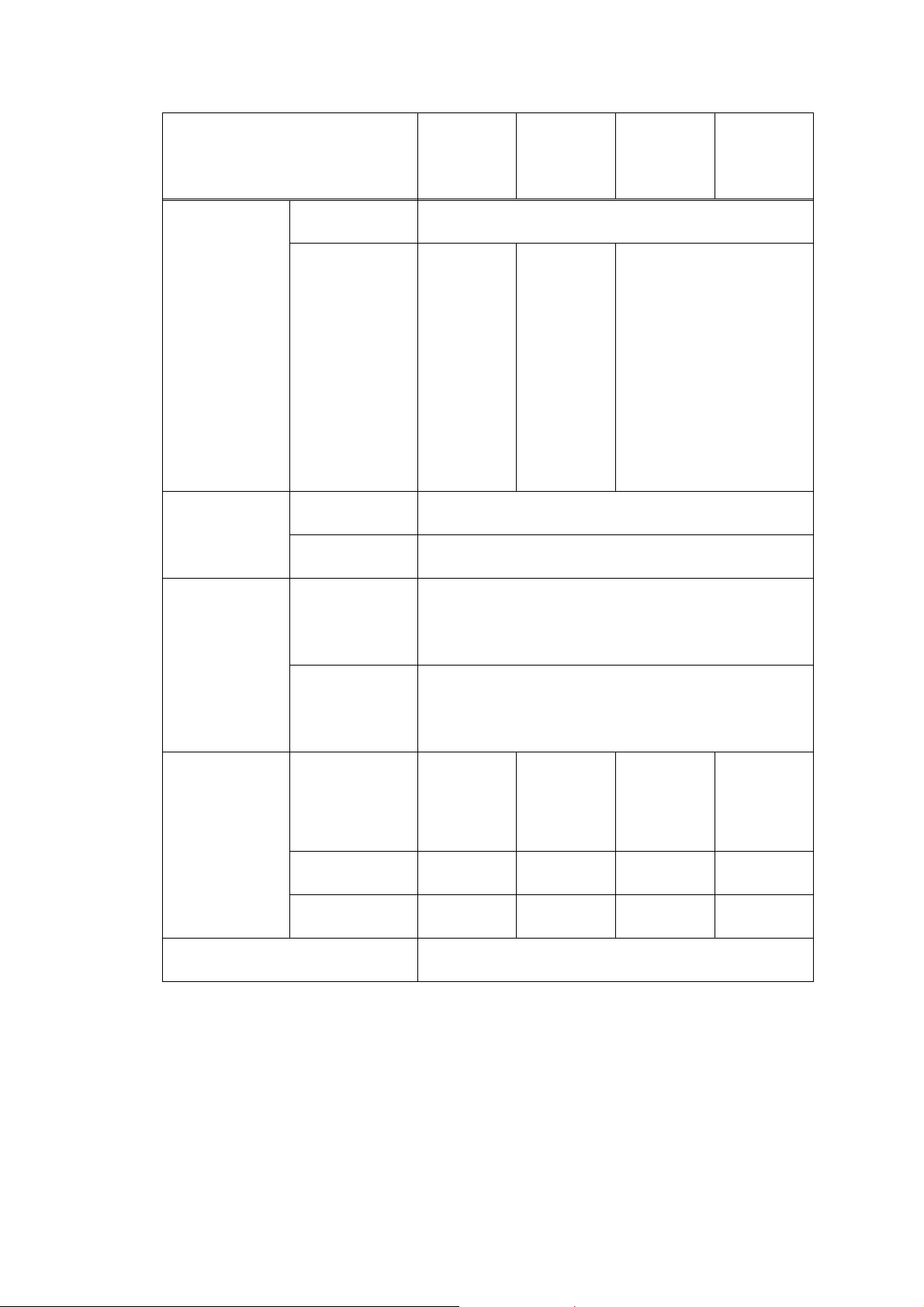
Specifications are subject to change without notice.
Model
DCP-7055
DCP-7055W
DCP-7057
DCP-7057E
DCP-7057W
DCP-7060D
DCP-7065DN
DCP-7070DW
HL-2280DW
Noise Level Sound pressure Printing: 53 dB (A)
Ready: 30 dB (A)
Sound power Printing:
6.60 B (A)
Ready:
4.30 B (A)
For U.S.A.
/China
Printing:
6.74 B (A)
Ready:
4.30 B (A)
Except for
U.S.A.
/China
Printing:
6.40 B (A)
Ready:
4.27 B (A)
For U.S.A.
Printing: 6.81 B (A)
Ready: 4.30 B (A)
Except for U.S.A.
Printing: 6.40 B (A)
Ready: 4.22 B (A)
Environment Temperature Operating: 10 to 32.5 °C
Storage: 0 to 40 °C
Humidity Operating: 20 to 80 %
Storage: 10 to 90 %
Dimensions
(W x D x H)
Carton Size
For models with ADF :
527 x 510 x 493 mm (20.8 x 20.1 x 19.4 inch)
For models without ADF :
527 x 510 x 440 mm (20.8 x 20.1 x 17.4 inch)
Machine Size
For models with ADF :
405 x 398.5 x 316 mm (15.95 x 15.7 x 12.45 inch)
For models without ADF :
405 x 398.5 x 268 mm (15.95 x 15.7 x 10.6 inch)
Weights With Carton
12.9 kg / 28.4 lb 13.2 kg / 29.1 lb 14.6 kg / 32.2 lb For U.S.A.
12.6 kg / 27.8 lb
Except for
U.S.A.
13.4 kg / 29.5 lb
Without Carton,
With toner/drum
9.8 kg / 21.6 lb 10.1 kg / 22.3 lb 11.4 kg / 25.1 lb 10.3kg / 22.7 lb
Without Carton
and toner/drum
8.6 kg / 19.0 lb 8.9 kg / 19.6 lb 10.2 kg / 22.5 lb 9.1 kg / 20.1 lb
LCD Size Except for China: 16 Characters x 2 lines
For China: 10 Characters x 2 lines
1-3
Confidential
Specifications are subject to change without notice.
Model MFC-7360
MFC-7360N
MFC-7362N
MFC-7365DN
MFC-7460DN
MFC-7470D
MFC-7860DN
MFC-7860DW
Print method Electrophotographic / Laser
Resolution 600 dpi x 600 dpi, HQ1200 (2400 X 600 dpi) quality
Print speed Up to 24/24 ppm For MFC-7365DN
Up to 24/24 ppm
Except for MFC-7365DN
Up to 26/27 ppm
* When loading A4 or Letter-size paper from the paper
tray.
Warm-up time From Sleep Mode: Less than 7seconds
* At 23°C (73.4F)
From Power OFF → ON:
Less than 27 seconds
From Power OFF
→
ON
For MFC-7365DN/7460DN
Less than 27 seconds
Except for MFC-7365DN/
7460DN
Less than 28 seconds
* At 23°C (73.4F)
First print time
From Ready mode
Less than 8.5 seconds
From Sleep mode
Less than 16.5 seconds
CPU ARM9 200MHz
Memory 16 MB 32 MB
Backup Clock Up to 2 hours For MFC-7365DN/7460DN
Up to 2 hours
Except for MFC-7365DN/
7460DN
Up to 60 hours
Interface Hi-Speed
USB 2.0
For MFC-7470D
Hi-Speed USB 2.0
Except for MFC-7470D
Hi-Speed USB 2.0,
Ethernet 10/100 BASE-TX
Hi-Speed USB
2.0, Ethernet
10/100 BASE-
TX,
IEEE802.11b/g
(Infrastructure
Mode / Adhoc
Mode)
Power
Consumption
* Measured with
only USB
connected
Peak 1080 W
Copying Average: Approximately 445 W
Ready Average: Approximately 55 W
Sleep, Wireless
LAN: ON
N/A Average:
Approximately
3.9 W
Deep Sleep Average: Approximately 1.5 W Average:
Approximately
1.7 W

1-4
Confidential
Specifications are subject to change without notice.
Model MFC-7360
MFC-7360N
MFC-7362N
MFC-7365DN
MFC-7460DN
MFC-7470D
MFC-7860DN
MFC-7860DW
Noise Level Sound pressure Printing: 53 dB (A)
Ready: 30 dB (A)
Sound power Printing: 6.74 B (A)
Ready: 4.30 B (A)
For Europe/
Oceania
Printing:
6.40 B (A)
Ready:
4.22 B (A)
Except for
Europe/
Oceania
Printing:
6.81 B (A)
Ready:
4.30 B (A)
For U.S.A.
Printing:
6.81 B (A)
Ready:
4.30 B (A)
Except for
U.S.A.
Printing:
6.40 B (A)
Ready:
4.22 B (A)
Environment Temperature Operating: 10 to 32.5 °C
Storage: 0 to 40 °C
Humidity Operating: 20 to 80 %
Storage: 10 to 90 %
Dimensions
(W x D x H)
Carton Size
For models without Handset:
527 x 510 x 493 mm (20.8 x 20.1 x 19.4 inch)
For models with Handset:
573 x 510 x 493 mm (22.6 x 20.1 x 19.4 inch)
Machine Size
For models without Handset:
405 x 398.5 x 316 mm (15.95 x 15.7 x 12.45 inch)
For models with Handset
:
477 x 398.5 x 316 mm (18.8 x 15.7 x 12.45 inch)
Weights With Carton
For Asia:
14.5 kg / 32.0 lb
For China:
15.1 kg / 33.3 lb
14.6 kg / 32.2 lb
For models without Handset:
14.8 kg / 32.6 lb
For models with Handset:
15.4 kg / 34.0 lb
Without Carton,
With toner/drum
For Asia:
11.3 kg / 24.9 lb
For China:
11.7 kg / 25.8 lb
11.4 kg / 25.1 lb
For models without Handset:
11.6 kg / 25.6 lb
For models with Handset:
11.9 kg / 26.2 lb
Without Carton
and toner/drum
For Asia:
10.1 kg / 22.3 lb
For China:
10.4 kg / 22.9 lb
10.2 kg / 22.5 lb
For models without Handset:
10.4 kg / 22.9 lb
For models with Handset:
10.6 kg / 23.4 lb
LCD Size Except for China: 16 Characters x 2 lines
For China: 10 Characters x 2 lines

1-5
Confidential
<Computer requirements>
Specifications are subject to change without notice.
Computer Platform &
Operating System
Version
Processor
Minimum
Speed
Minimum
RAM
Recom-
mended
RAM
Hard Disk Space
to install
Supported
PC
Software
Functions
Supported
PC
Interface
*3
For
Drivers
For
Appli-
cations
Windows
®
Operating
System
*1
Windows
®
2000
Professional
*4
Intel
®
Pentium
®
II or equivalent
64 MB 256 MB
150 MB 500 MB
Printing,
Scanning
USB,
10/100
Base Tx
(Ethernet),
Wireless
802.11 b/g
Windows
®
XP
Home
*2
*5
Windows
®
XP
Professional
*2
*5
128 MB
Windows
®
XP
Professional
x64 Edition
*2
*5
64-bit (Intel
®
64
or AMD 64)
supported CPU
256 MB 512 MB
Windows Vista
®
*2
*5
Intel
®
Pentium
®
4 or equivalent
64-bit (Intel
®
64
or AMD 64)
supported CPU
512 MB 1 GB
500 MB 1.2 GB
Windows
®
7
*2
*5
Intel
®
Pentium
®
4 or equivalent
64-bit (Intel
®
64
or AMD 64)
supported CPU
1 GB
(32-bit)
2 GB
(64-bit)
1 GB
(32-bit)
2 GB
(64-bit)
650 MB
Windows
Server
®
2003
(print only via
network)
Intel
®
Pentium
®
III or equivalent
256 MB 512 MB 50 MB N/A
Printing
10/100
Base Tx
(Ethernet),
Wireless
802.11 b/g
Windows
Server
®
2003
x64 Edition
(print only via
network)
64-bit (Intel
®
64
or AMD 64)
supported CPU
Windows
Server
®
2008
(print only via
network)
Intel
®
Pentium
®
4 or equivalent
64-bit (Intel
®
64
or AMD 64)
supported CPU
512 MB 2 GB
Windows
Server
®
2008
R2 (print only
via network)
64-bit (Intel
®
64
or AMD 64)
supported CPU
Macintosh
Operating
System
Mac OS X
10.4.11
10.5.x
PowerPC
®
G4/G5
Intel
®
Core™
Processor
512 MB 1 GB 80 MB
400 MB
Printing,
Scanning
USB,
10/100
Base Tx
(Ethernet),
Wireless
802.11 b/g
Mac OS X
10.6.x
Intel
®
Core™
Processor
1 GB 2 GB
*1 Internet Explorer
®
6.0 or greater.
*2 For WIA, 1200 x 1200 resolution. Brother Scanner Utility enables to enhance up to
19200 x 19200 dpi.
*3 Third-party USB ports are not supported.
*4 PaperPort™ 11SE supports Microsoft
®
SP4 or higher for Windows
®
2000.
*5 PaperPort™ 12SE supports Microsoft
®
SP3 or higher for Windows
®
XP and SP2 or higher
for Windows Vista
®
and Windows
®
7.
1-6
Confidential
1.2 Network Connectivity
Specifications are subject to change without notice.
Model
DCP-7055/7057
DCP-7057E/7060D
MFC-7360/7470D
DCP-7055W
DCP-7057W
DCP-7065DN
MFC-7360N
MFC-7362N
MFC-7365DN
MFC-7460DN
MFC-7860DN
DCP-7070DW
HL-2280DW
MFC-7860DW
Wired
network
Network node
type
N/A NC-8200h
Network type
N/A Ethernet 10/100 BASE-TX
Network
security
N/A APOP, POP before SMTP,
SMTP-AUTH
Wireless
network
Network node
type
N/A
NC-7800w
N/A NC-7800w
Network type
N/A IEEE802.11b/g
(Infrastructure
Mode / Adhoc
Mode)
N/A IEEE802.11b/g
(Infrastructure
Mode / Adhoc
Mode)
Communication
mode
N/A Infrastructure,
Ad-hoc
N/A Infrastructure,
Ad-hoc
Network
security
N/A WEP 64/128 bit,
WPA-PSK
(TKIP/AES),
WPA2-PSK
(AES), APOP,
POP before
SMTP, SMTP-
AUTH
N/A WEP 64/128 bit,
WPA-PSK
(TKIP/AES),
WPA2-PSK
(AES), APOP,
POP before
SMTP, SMTP-
AUTH

1-7
Confidential
1.3 Service Information
Specifications are subject to change without notice.
Part Approximate Life (pages)
Machine life 50,000 pages (A4 / LTR) or 5 years under normal use at
normal temperature and humidity.
Part life (ADF) 50,000 pages
Part life
(Document Scanner Unit)
50,000 pages
MTBF 4,000 hours
MTTR 0.5 hours
Maximum monthly volume
DCP-7055/7055W/7057/7057E/7057W: Up to 8,000 pages
Other models: Up to 10,000 pages
Part life (Fuser unit) 50,000 pages
Part life (Laser unit)
Part life (PF kit)

1-8
Confidential
1.4 Consumables
Specifications are subject to change without notice.
Consumables Approximate Life
Toner
cartridge
Starter
Toner
<For China/Asia, Europe in DCP-7065DN/MFC-7460DN/
MFC-7860DW, DCP-7057W, DCP-7070DW, MFC-7360>
N/A
<Other models>
Approximately 700 pages/cartridge
* When printing A4/Letter-size one sided pages in accordance with
ISO/IEC 19752.
Shelf life: 2 years without opening (6 months after opening)
Standard
Toner
<DCP-7055/7055W/7057/7057E/7057W, Europe in DCP-7057>
Except for China/Asia: Approximately 1,000 pages/cartridge
For China/Asia in DCP-7055: Approximately 700 pages/cartridge
<Other models>
Approximately 1,200 pages/cartridge
* When printing A4/Letter-size one sided pages in accordance with
ISO/IEC 19752.
Shelf life: 2 years without opening (6 months after opening)
High
Capacity
<DCP-7055/7055W/7057E/7057W, Europe in DCP-7057>
N/A
<Other models>
Approximately 2,600 pages/cartridge
* When printing A4/Letter-size one sided pages in accordance with
ISO/IEC 19752.
Shelf life: 2 years without opening (6 months after opening)
Drum unit Life expectancy: Approximately 12,000 pages/drum unit
The life expectancy varies according to the use condition. (Refer to
Display of the machine’s log (Function code 80 in Chapter 5.))
* When printing A4/Letter-size one sided pages in accordance with
ISO/IEC 19752.
Shelf life: 2 years
The shelf life of toner cartridge and drum unit is guaranteed under the normal condition as
below;
(Temperature) Normal condition: 0 to 40 °C
* Storage condition at the temperature of 40 to 50 °C: Up to 5 days
* Storage condition at the temperature of -20 to 0 °C: Up to 5 days
(Humidity) Normal condition: 35 to 85 %
* Storage condition at the humidity of 85 to 95 %: Up to 5 days
* Storage condition at the humidity of 10 to 35%: Up to 5 days
Loading...