


Broan HEPA 4000, HEPA 1000, HEPA 3000, HEPA 2000 User Manual
INSTALLATION INSTRUCTIONS
AND USER MANUAL
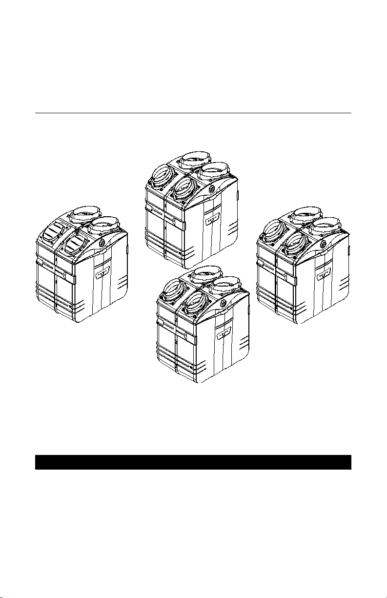
MODELS
HEPA 2000*
HF 2.0*
HEPA 1000*
HF 1.0*
VB0061
*Patents pending
NOTE: HEPA 4000 model available in United States only.
RESIDENTIAL USE ONLY
READ AND SAVE THESE INSTRUCTIONS
INSTALLER: LEAVE THIS MANUAL WITH THE HOMEOWNER.
HOMEOWNER: USE AND CARE INFORMATION
ON PAGES 28 and 32 to 36.
HEPA 4000*
HEPA 3000*
HF 3.0*
04313 rev C
ABOUT THIS MANUAL
!
First, we want to congratulate you on your purchase of this excellent unit which will
allow you and your family to enjoy clean and health
years to come!
Because of the large amount of models covered by this publication, the illustrations
are typical ones. Some details of your unit may be slightly different than the ones
shown.
Please take note that this manual uses the following symbols to emphasize
particular information:
WARNING
Identifies an instruction which, if not followed, might cause serious
personal injuries including possibility of death.
CAUTION
Denotes an instruction which, if not followed, may severely damage the unit
and/or its components.
NOTE: Indicates supplementary information needed to fully complete an instruction.
We welcome any suggestions you may have concerning this manual and/or the
unit, and we would appreciate hearing your comments on ways to better serve you.
Please contact us by phone at one of the following numbers:
y air throughout your home for
Exclusiv
Broan-NuTone Canada Inc. Venmar Ventilation inc.
1 866 737-7770 1 800 567-3855
ely for all HF Models: Exclusively for all HEPA Models:
- 2 -!- 3 -

ABOUT THESE UNITS
WARNING
TO REDUCE THE RISK OF FIRE, ELECTRIC SHOCK, OR INJURY TO
PERSON(S) OBSERVE THE FOLLOWING:
1. This unit is intented for residential installation only.
2. Use this unit only in the manner intended by the manufacturer. If you have
questions, contact the manufacturer at the address or telephone number listed
in the warranty.
3. Before replacing filters, servicing or cleaning unit, disconnect power cord from
electrical outlet.
4. Installation must be done in accordance with all applicable codes and standards,
including fire-rated construction codes and standards.
5. This unit is not designed to provide combustion and/or dilution air for fuel-burning
appliances.
6. When cutting or drilling into wall or ceiling, do not damage electrical wiring and
other hidden utilities.
7. Do not use this unit with any solid-state speed control device other than
optional wall controls C12, CM, C34 and CMR (sold separately).
8. This unit must be grounded. The power supply cord has a 3-prong grounding
plug for your personal safety. It must be plugged into a mating 3-prong grounding
receptacle, grounded in accordance with the national electrical code and local
codes and ordinances. Do not remove the ground prong. Do not use an
extension cord.
9. Do not install in a cooking area or connect directly to any appliances.
10. Do not use to exhaust hazardous or explosive materials and vapors.
CAUTION
1. To avoid prematurate clogged filters, turn OFF the unit during construction or
renovation.
2. Please read specification label on product for further information and requirements.
3. For HEPA 2000, HF 2.0, HEPA 3000, HF 3.0 and HEPA 4000 units only: Be
sure to duct air outside – Do not intake / exhaust air into spaces within walls
or ceiling or into attics, crawl spaces, or garage.
4. Itended for residential installation only in accordance with the requirements of
NFPA 90B.
5. Do not run any air ducts directly above or closer than 2 ft (0.61 m) to any furnace
or its supply plenum, boiler, or other heat producing appliance. For HEPA 2000,
HF 2.0, HEPA 3000, HF 3.0 and HEPA 4000 units only, if a duct has to be
connected to the furnace return plenum, it must be connected not closer than
9’10” (3 m) from this plenum connection to the furnace. For HEPA 1000 and
HF 1.0 units only, the distance must be not closer than 2’ (0.61 m).
6. The ductwork is intended to be installed in compliance with all local and
national codes that are applicable.

TABLE OF CONTENTS
1.0 BEFORE STARTING . . . . . . . . . . . . . . . . . . . . . . . . . . . .6
1.1 Inspect the Content of the Boxes . . . . . . . . . . .. . 6
2.0 TYPICAL INSTALLATIONS . . . . . . . . . . . . . . . . . . . . . . . .6
2.1 HEPA 1000 and HF 1.0 Unit Installations . . . . . . 7
2.1.1 Stand Alone . . . . . . . . . . . . . . . . . . . . . . . . . .7
2.1.2 Central Draw Point . . . . . . . . . . . . . . . . . . . . .8
2.1.3 Return-to-Return Installation . . . . . . . . . . . . . . . .9
2.2 Installations for HEPA 4000 Only . . . . . . . . . . . .10
2.2.1 Geographical Location . . . . . . . . . . . . . . . . .10
2.2.2 HEPA 4000 Attic Installation . . . . . . . . . . . . . .11
2.3 HEPA 2000, HF 2.0, HEPA 3000, HF 3.0
and HEPA 4000 Unit Installations . . . . . . . . . . . .12
2.3.1 Stand Alone . . . . . . . . . . . . . . . . . . . . . . . . .12
2.3.2 Central Draw Point . . . . . . . . . . . . . . . . . . . .13
2.3.3 Return-to-Return Installation . . . . . . . . . . . . . . .14
3.0 DIMENSIONS . . . . . . . . . . . . . . . . . . . . . . . . . . . . . .15
3.1 HEPA 1000 and HF 1.0 Units . . . . . . . . . . . . . .15
3.2 HEPA 2000, HF 2.0, HEPA 3000, HF 3.0
and HEPA 4000 units . . . . . . . . . . . . . . . . . . . .15
3.3 Mounting and Servicing Considerations . . . . . . . .16
4.0 INSTALL THE UNIT . . . . . . . . . . . . . . . . . . . . . . . . . . .17
4.1 Locating and Mounting the Unit . . . . . . . . . . . . .17
4.2 Mount the Ports on the Unit . . . . . . . . . . . . . . . .17
4.3 How to Hang the Unit . . . . . . . . . . . . . . . . . . .18
4.4 Planning of the Ductwork . . . . . . . . . . . . . . . . .19
4.5 Installing Ductwork and Registers . . . . . . . . . . . .20
4.5.1 Stand Alone System . . . . . . . . . . . . . . . . . . .20
4.5.2 Central Draw Point . . . . . . . . . . . . . . . . . . . .21
4.5.3 Return-to-Return . . . . . . . . . . . . . . . . . . . . . .22
- 4 -

TABLE DES MATIÈRES
4.6 Installation des conduit flexibles isolés . . . . . . . . .23
4.6.1 Raccordement à la transition Tandem® . . . . . .23
4.6.2 Raccordement aux bouches ovales de 5”à 6” . .24
4.7 Installation de la bouche extérieure double . . . . . .25
4.7.1 Assemblage de la bouche extérieure double . . .25
4.7.2 Localisation de la bouche extérieure double . . .25
4.7.3 Raccordement de la transition Tandem®
à la bouche extérieure double . . . . . . . . . . . . .25
4.8 Raccordement du boyau de drainage . . . . . . . . .27
5.0 CONTRÔLES . . . . . . . . . . . . . . . . . . . . . . . . . . . . . . .28
5.1 Interrupteur principal . . . . . . . . . . . . . . . . . . . .28
5.2 Contrôle muraux optionnels . . . . . . . . . . . . . . . .28
5.3 Dimensions . . . . . . . . . . . . . . . . . . . . . . . . . .28
5.4 Installation des contrôles muraux optionnels . . . . .29
5.5 Fonctionnement du contrôle C12 / CM . . . . . . . .32
5.5.1 Description du contrôle C12 / CM . . . . . . . . .32
5.5.2 Utilisation du contrôle C12 / CM . . . . . . . . . .32
5.6 Fonctionnement du contrôle C34 / CMR . . . . . . .33
5.6.1 Description du contrôle C34/ CMR . . . . . . . .33
5.6.2 Utilisation du contrôle C34 / CMR . . . . . . . . .33
6.0 ENTRETIEN . . . . . . . . . . . . . . . . . . . . . . . . . . . . . . .34
6.1 Entretien semestriel . . . . . . . . . . . . . . . . . . . . . .34
6.2 Entretien annuel . . . . . . . . . . . . . . . . . . . . . . .36
6.3 Réinitialisation générale . . . . . . . . . . . . . . . . . . .36
7.0 PIÈCES DE SERVICE . . . . . . . . . . . . . . . . . . . . . . . . . .37
8.0 D
ÉPANNAGE . . . . . . . . . . . . . . . . . . . . . . . . . . . . . .38
- 5 -
1. BEFORE STARTING
!
1
.1 INSPECT THE CONTENTS OF THE BOXES
WARNING
To avoid risk of suffocation, discard the plastic bag wrapping the unit.
• Inspect the exterior of the unit for shipping damage. Ensure that there is
no damage to the door, door latches, main switch, etc.
CAUTION
Remove the cardboard strip inside the unit (if applicable).
• Inspect the interior of the unit for damage. Ensure that blower assembly, heat
recovery core (HEPA 3000 et HF 3.0), energy recovery core (HEPA 4000),
insulation, dampers (HEPA 2000, HF 2.0, HEPA 3000, HF 3.0 and HEPA 4000),
prefilter, HEPA filter, etc. are all intact.
2. TYPICAL INSTALLATIONS
Installations may vary according to the model number and the position in which
the unit is installed. Use the following illustrations as guidelines to help you decide
on how your unit will be installed.
All the units should be hung to the joist, and installed either vertically or
horizontally. NOTE: For more details, see Point 5.3 in Section 5 INSTALL THE
UNIT.
In every case, bathroom fans and a range hood should be used to exhaust stale
air. Also, for homes with more than one level, we recommend one exhaust
register at the highest level.
There are 3 installation methods: Stand Alone, Central Draw Point and Return-toReturn Installation.
NOTE: An electrical outlet has to be available within 3 feet from the unit.
- 6 -
2. TYPICAL INSTALLATIONS (CONT’D)
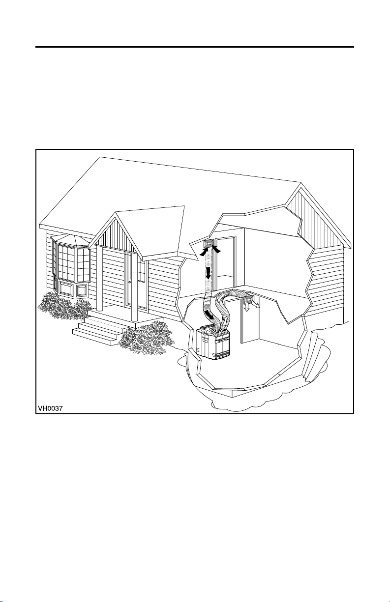
2.1 HEPA 1000 AND HF 1.0 UNIT INSTALLATIONS
2.1.1 STAND ALONE (Primarily for homes with radiant hot water or electric
baseboard heating.)
Stale air is drawn to the unit by the register located at the highest level of the
house. Filtered air is supplied by the register located at the lowest level.
See figure below.
- 7 -

2. TYPICAL INSTALLATIONS (CONT’D)
2.1 HEPA 1000 AND HF 1.0 UNIT INSTALLATIONS (CONT’D)
2.1.2 CENTRAL DRAW POINT (CONNECTION TO FORCED AIR SYSTEM)
Stale air is drawn to the unit by the register located at the highest level of the
house. Filtered air is supplied to the retur
For this type of installation, it is not essential that the forced air system blower
runs when the unit is in operation, but we recommend it.
See figure below.
NOTE: Home with multiple forced air systems should have 1 unit on each system.
n (plenum) of the forced air unit.
VH0038
CAUTION
Do not connect the unit (HEPA 1000 or HF 1.0) on any forced air system supply
duct. Connect it only to the air return duct. Do not install duct or duct
connector directly above the forced air unit or not less than 2’ (0.61 m) of the
plenum connection to the forced air unit, as measured along the length of
the duct.
- 8 -

2. TYPICAL INSTALLATIONS (CONT’D)
2.1 HEPA 1000 AND HF 1.0 UNIT INSTALLATIONS (CONT’D)
2.1.3 RETURN-RETURN INSTALLATION (CONNECTION TO A FORCED AIR SYSTEM)
Filtered air and stale air flow through the forced air system ducts which simplifies
the installation. Filtered air is supplied to the return (plenum) of the forced air unit.
To avoid cross-contamination and achieve highest efficiencies, the f
blower must always be ON (or the unit efficiency will be affected).
See figure below.
NOTE: Home with multiple forced air systems should have 1 unit on each system.
orced air system
CAUTION
Do not connect the unit (HEPA 1000 or HF 1.0) on any forced air system supply
duct. Connect it only to the air return duct. Do not install duct or duct
connector directly above the forced air unit or not less than 2’ (0.61 m) of the
plenum connection to the forced air unit, as measured along the length of
the duct.
- 9 -
2. TYPICAL INSTALLATIONS (CONT’D)
S
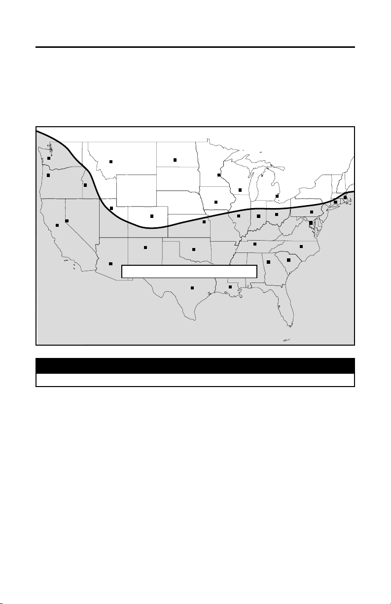
2.2 INSTALLATION FOR HEPA 4000 ONLY
2.2.1 GEOGRAPHICAL LOCATION
The HEPA 4000 unit was created to meet specific requirements related to
geographic locations. Take a look on the map below. The shaded area shows
where the HEPA 4000 can be installed.
BOISE
HELENA
SALT LAKE CITY
PHOENIX
DENVER
SANTA FE
BISMARCK
TOPEK
A
OKLAHOMA CITY
ST. PAUL
MADISON
DES MOINES
SPRINGFIELD
DETROIT
INDIANAPOLIS
NASHVILLE
ATLANTA
HARRISBURG
COLUMBUS
BO
HARTFORD
WASHINGTON
RALEIGH
COLUMBIA
OLYMPIA
SALEM
RENO
SACRAMENTO
HEPA 4000 RESTRICTED AREA
AUSTIN
VN0005A
BATON ROUGE
CAUTION
Never install an HEPA 4000 unit out of the HEPA 4000 restricted area.
NOTE:The HEPA 4000 unit is designed to assist in the management of humidity
introduced into the home. In extreme humidity conditions, the use of additional
dehumidification may be desirable.Quickly remove all excess moisture and
keep areas clean.
- 10 -
2. TYPICAL INSTALLATIONS (CONT’D)
2.2 INSTALLATION FOR HEPA 4000 ONLY (CONT’D)
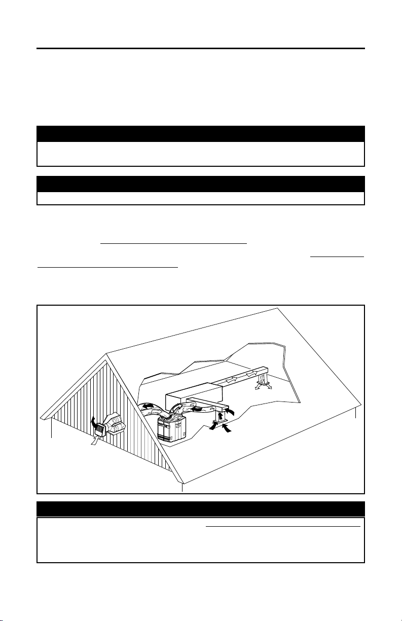
2.2.2 HEPA 4000 ATTIC INSTALLATION
All 3 types of installation can be used in the attic (Stand Alone, Central Draw Point
or Return-Return). The example shown below is a Return-Return installation
(connection to a forced air system).
CAUTION
Due to the potential temperature difference between the attic and the rest of
the house, all unit ducts must be insulated.
CAUTION
The attic temperature must always be above 0°C (32°F).
A portion of stale air is exhausted to the outside and the rest is drawn to the unit.
Outside fresh air is blended with interior air and then filtered. This filtered air is
supplied to the retur
To avoid the cross-contamination and achieve highest efficiencies, the forced air
system blower must always be ON (or the unit efficiency will be affected).
See figure below.
NOTE: Home with multiple forced air systems should have 1 unit on each system.
n (plenum) of the forced air unit.
VH0051
CAUTION
Do not connect the HEPA 4000 on any forced air system supply duct.
Connect it only to the air return duct. Do not install duct or duct connector
directly above the forced air unit or not less than 9’10’’ (3 m) of the plenum
connection to the forced air unit, as measured along the length of the duct.
- 11 -
2. TYPICAL INSTALLATIONS (CONT’D)
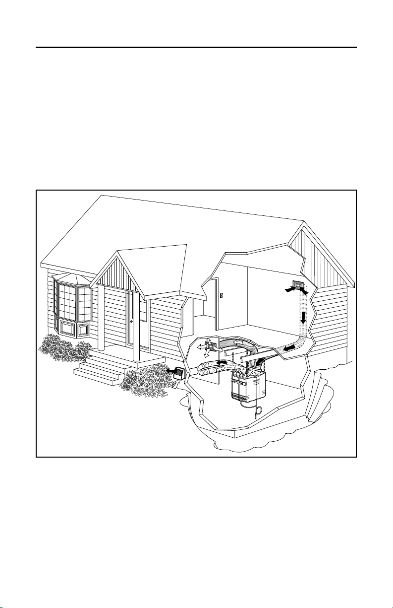
2.3 HEPA 2000, HF 2.0, HEPA 3000, HF 3.0 AND HEPA 4000
UNIT INSTALLATIONS
2.3.1 STAND ALONE (Primarily for homes with radiant hot water or electric
baseboard heating.)
A portion of stale air (coming from the register located at the highest level of the
house) is exhausted to the outside and the rest is drawn to the unit. Outside fresh
air is blended with interior air and then filtered. Fresh filtered air is supplied by the
register located in the lowest livable level. See figure below.
VH0039
- 12 -
 Loading...