


Broan PM500SS Installation Manual

POWER
MODULE
REGISTER YOUR PRODUCT ONLINE AT www.broan.com/register
READ AND SAVE THESE INSTRUCTIONS
PM500 SERIES
!
INTENDED FOR DOMESTIC COOKING ONLY
WARNING
TO REDUCE THE RISK OF FIRE, ELECTRIC SHOCK, OR INJURY
TO PERSONS, OBSERVE THE FOLLOWING:
1. Use this unit only in the manner intended by the manufacturer. If you
have questions, contact the manufacturer at the address or telephone number listed in the warranty.
2. Before servicing or cleaning unit, switch power off at service panel
and lock service panel to prevent power from being switched on
accidentally. When the service disconnecting means cannot be
locked, securely fasten a prominent warning device, such as a tag,
to the service panel.
3. Installation work and electrical wiring must be done by a qualified
person(s) in accordance with all applicable codes and standards,
including fire-rated construction codes and standards.
4. Sufficient air is needed for proper combustion and exhausting of
gases through the flue (chimney) of fuel burning equipment to prevent backdrafting. Follow the heating equipment manufacturer’s
guidelines and safety standards such as those published by the National Fire Protection Association (NFPA), and the American Society for Heating, Refrigeration and Air Conditioning Engineers
(ASHRAE), and the local code authorities.
5. When cutting or drilling into wall or ceiling, do not damage electrical
wiring and other hidden utilities.
6. Ducted fans must always be vented to the outdoors.
7. Do not use this unit with any separate solid-state speed control device.
8. To reduce the risk of fire, use only metal ductwork.
9. This unit must be grounded.
TO REDUCE THE RISK OF A RANGE TOP GREASE FIRE:
A. Never leave surface units unattended at high settings. Boilovers cause
smoking and greasy spillovers that may ignite. Heat oils slowly on
low or medium settings.
B. Always turn hood ON when cooking at high heat or when flambeing
food (i.e. Crepes Suzette, Cherries Jubilee, Peppercorn Beef
Flambe’).
C. Clean ventilating fans frequently. Grease should not be allowed to
accumulate on fan or filter.
D. Use proper pan size. Always use cookware appropriate for the size
of the surface element.
!
!
CAUTION
1. For indoor use only.
2. To reduce risk of fire and to properly exhaust air, be sure to duct air
outside. Do not vent exhaust air into spaces within walls or ceilings
or into attics, crawl spaces, or garages.
3. Take care when using cleaning agents or detergents.
4. Avoid using food products that produce flames under the Range Hood.
5. For general ventilating use only. Do not use to exhaust hazardous or
explosive materials and vapors.
6. To avoid motor bearing damage and noisy and/or unbalanced impellers, keep drywall spray, construction dust, etc. off power unit.
7. Your hood motor has a thermal overload which will automatically shut
off the motor if it becomes overheated. The motor will restart when it
cools down. If the motor continues to shut off and restart, have the
hood serviced.
8. For best capture of cooking impurities, the bottom of the hood should
be a minimum of 22" and a maximum of 30" above the cooking
surface.
9. Two installers are recommended.
10. Use with approved cord-connection kit only.
11. Please read specification label on product for further information and
requirements.
!
CAUTION
WARNING
TO REDUCE THE RISK OF INJURY TO PERSONS IN THE EVENT
OF A RANGE TOP GREASE FIRE, OBSERVE THE FOLLOWING:*
1. SMOTHER FLAMES with a close-fitting lid, cookie sheet, or metal
tray, then turn off the burner. BE CAREFUL TO PREVENT BURNS.
If the flames do not go out immediately, EVACUATE AND CALL
THE FIRE DEPARTMENT.
2. NEVER PICK UP A FLAMING PAN - You may be burned.
3. DO NOT USE WATER, including wet dishcloths or towels - violent
steam explosion will result.
4. Use an extinguisher ONLY if:
A. You know you have a Class ABC extinguisher and you already
know how to operate it.
B. The fire is small and contained in the area where it started.
C. The fire department is being called.
D. You can fight the fire with your back to an exit.
* Based on “Kitchen Fire Safety Tips” published by NFPA.
Wear safety gloves before every installation
and/or maintenance operation
INSTALL THE DUCTWORK
NOTE: To reduce the risk of fire, use only metal ductwork.
1. Decide where the ductwork will run between the hood and the
outside (Refer to Figure 1).
2. A straight, short duct run will allow the hood to perform most
efficiently.
3. Long duct runs, elbows, and transitions will reduce the performance
of the hood. Use as few of them as possible. Larger ducting may
be required for best performance with longer duct runs.
4. Install a roof or wall cap. Connect round metal ductwork to cap
and work back towards hood location. Use duct tape to seal the
joints between ductwork sections.
ROOF CAP
ROUND
DUCT
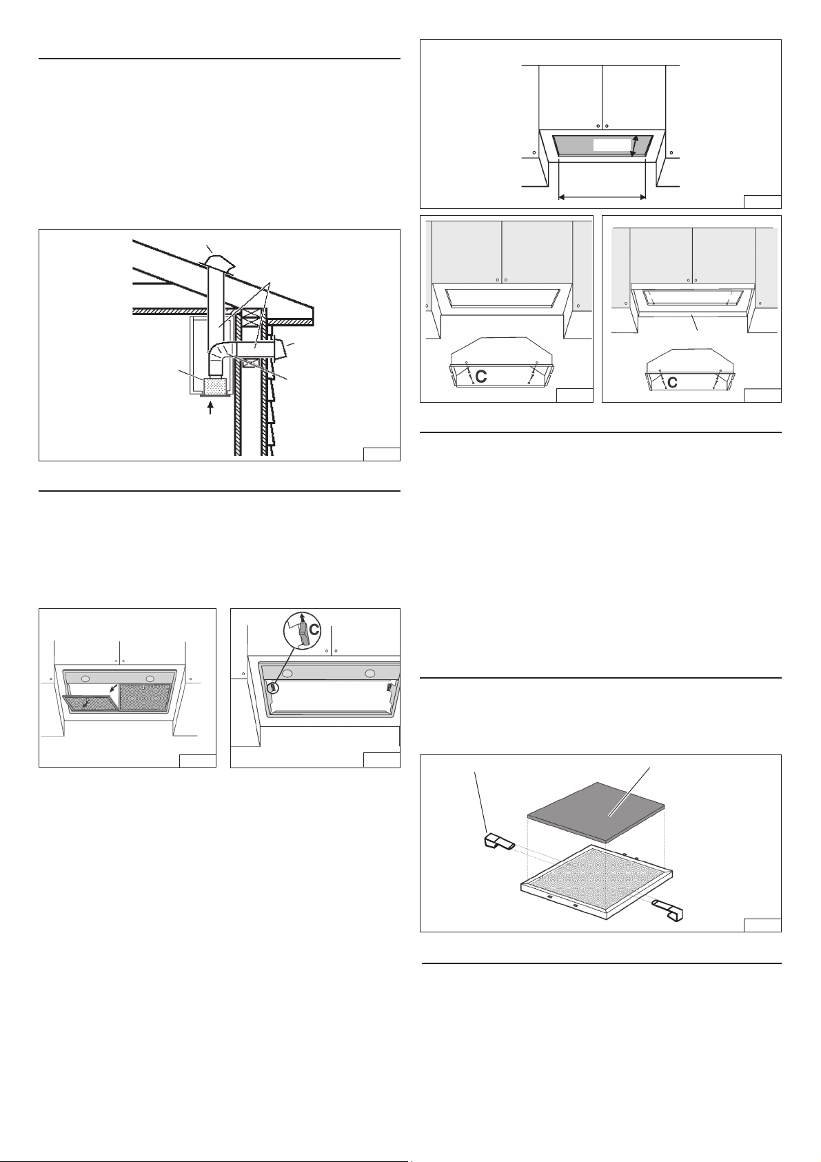
CUT A HOLE IN THE BOTTOM OF THE CABINET
10-1/4”
19-1/2”
FIG. 4
WALL
CAP
POWER
MODULE
22” TO 30” ABOVE
COOKING SURFACE
6”
ROUND
ELBOW
FIG. 1
INSTALL THE HOOD
NOTE: the hood has to be installed, inside the cabinet.
The internal height of cabinet has to be minimum 16”.
The hood should be mounted centered over the cook top burners.
1. Remove the grease filters, push in on the metal latch tab. Tilt
the filters downward and remove (Fig. 2).
2. Take the filters support away moving the 2 lateral locks C (Fig. 3).
METAL LINER
FIG. 5 FIG.5A
CONNECT DUCTWORK
Ducted Configuration
1. Take the damper and assemble it onto the hood’s discharge
opening, pressing slightly.
2. Use 6" round metal duct to connect the discharge collar on the
hood to the ductwork above.
3. Use duct tape to make all joints secure and air tight.
Non-Ducted Recirculation Configuration
1. Connect a 6” round metal duct to the discharge opening so
that the air is sent outside the cabinet and sent back into the
room.
2. Use duct tape to make all joints secure and air tight.
NON-DUCTED RECIRCULATION FILTERS
INSTALLATION
Install the Non-ducted recirculation filters over the grease filters and
secure them with the metal clips supplied with the Non-ducted
recirculation Filters (Fig. 6).
FIG. 2
FIG. 3
3. Cut a hole in the bottom of the cabinet, using the dimensions shown
(Fig. 4).
4. NOTE: For installations where the Power Pack is less than 30”
above cook top, it is recommended that the Power Pack be
mounted into a metal liner or non-combustible material. This will
allow easier cleaning and provide protection to the cabinetry
(Fig.5A).
5. Insert the hood in the cabinet (Fig. 5) or metal liner (Fig. 5A) and
secure with the (4) “C” mounting sheet metal screws.
(Fig. 5 - wood bottom installation; recommended thickness 1/2”3/4”).
(For alternate mounting, use machine screws with washers and
nuts. This alternate mounting method needs to be done prior to
installation of metal liner).
6. Replace the filters support.
7. In the Non-Ducted Recirculation Configuration, install the Nonducted recirculation Filters before replacing the grease filters (see
section “Non-ducted recirculation filters installation”).
8. Replace the grease filters.
9. Install the switch push button covers supplied in the hardware
package.
METAL CLIPS
NON-DUCTED
RECIRCULATION FILTER
(purchased seperately)
FIG. 6
WIRING
Note: This range hood must be properly grounded.
The unit should be installed by a qualified electrician in accor-
dance with all applicable national and local electrical codes.
1. Remove the wiring box cover. Remove a knockout from the wiring
box.
2. Secure the conduit to the wiring box through a conduit connector.
3. Make electrical connections. Connect white to white, black to black
and green to green.
4. Replace wiring box cover and screws. Make sure that wires are
not pinched between cover and box.

WIRING BOX
FIG. 7
OPERATION
Controls
The light switch turns the halogen lights on and off.
The blower off switch turns the blower off.
The blower low speed switch turn the blower speed to low.
The blower medium speed switch turn the blower speed to
medium.
The blower high speed switch turn the blower speed to to high.
The pilot lamp lights up whenever the blower is on.
BLOWER
LOW SPEED
BLOWER
OFF
LIGHT
FIG. 8
PILOT
LAMP
BLOWER
HIGH
SPEED
BLOWER
MEDIUM
SPEED
MAINTENANCE
ALWAYS SWITCH OFF THE ELECTRICITY SUPPLY BEFORE
CARRYING OUT ANY OPERATIONS ON THE APPLIANCE.
Grease Filters
The grease filters should be cleaned frequently. Use a warm
detergent solution. Grease filters is dishwasher safe.
To remove the grease filters: push in on the metal latch tab. Tilt the
filters downward and remove (Fig. 2).
Non-Ducted Recirculation Filters
The Non-Ducted Recirculation filters (purchase seperately) should
be changed every 6 months.
To remove the Non-Ducted Recirculation filters:
1. To remove the grease filters: push in on the metal latch tab. Tilt
the filters downward and remove (Fig. 2).
2. Remove the metal wires (Fig. 6) and replace the Non-ducted
recirculation Filters.
Cleaning
Occasional care will help preserve its fine appearance.
• Clean with warm water and mild detergent only.
• Follow all cleaning by rinsing with clear water.
• Wipe dry with clean, soft cloth.
Halogen bulbs
This range hood requires two 20-Watt halogen bulbs.
To change bulbs:
1. Remove filters.
2. Remove frame.
3. Remove the lamp cover by prying from the proper slots (Fig. 9). DO NOT ROTATE. CAUTION: BULB MAY BE HOT!
4. Replace with light bulbs of the same type (Type T3, 12Volt, 20
Watt Max, G-4 Base).
SERVICE PARTS
KEY NO. PART NO. DESCRIPTION
1 B003102348 Frame
4 B03293065 Side Fastener
6 B02011013 Spring
9 B08087039 Grease Filter
14 B02300233 Condenser
19 B03295104 Transformer Protection
26 B02300891 Halogen Lamp Bulb
45 BW0000021 Blower
48 B02310260 Motor
49 B03295071 Blower Wheel
53 B03204177 Rubber Washer
86 B08088378 Damper
115 BE3334250 Wiring Box
116 BE3334252 Wiring Box Cover
134 B03293066 Grid Stop
165 B03295008 Box Condenser
208 B02300861 Transformer
223 B03200376 Blower Switch
228 B08086303 Controls Board
229 B03201014 Pilot Lamp
230 B03294831 Control Box Cover
234 B03294830 Control Box
274 B03295035 Fuse Box
472 BE3348670 Controls Bracket
474 B02300798 Halogen Lamp
477 B03295105 Transformer Protection Cover
998 B080810886 Hardware Package
AQI B06108858 Switch box Assembly
(Included Key No. 234, 228,
14, 230)
- B08999053 Non-Ducted Filter Kit
(purchased separately)
FIG. 9
 Loading...