


READ AND SAVE THESE INSTRUCTIONS
Installer: leave this guide with homeowner.
Register your product online at www.broan.com/register.
LP80 & LP110
Lo Profile
Ventilation Fan
INSTALLATION GUIDE
Easy installation
© 2018 Broan
Table of Contents
Warnings and Cautions 2
Typical Installation 2
Installation 3-6
Operation 7
Cleaning and Maintenance 7
Troubleshooting 7
Service Parts 8
Warranty 8

Page 2
LP80 & LP110
n
Installation Guide
WARNING
TO REDUCE THE RISK OF FIRE, ELECTRIC SHOCK, OR
INJURY TO PERSONS, OBSERVE THE FOLLOWING:
1. Use this unit only in the manner intended by the manufacturer.
If you have questions, contact the manufacturer at the address
or telephone number listed in the warranty.
2. Before servicing or cleaning unit, switch power off at service
panel and lock the service disconnecting means to prevent
power from being switched on accidentally. When the service
disconnecting means cannot be locked, securely fasten a
prominent warning device, such as a tag, to the service panel.
3. Installation work and electrical wiring must be done by a
qualified person(s) in accordance with all applicable codes
and standards, including fire-rated construction codes and
standards.
4. Sufficient air is needed for proper combustion and exhausting
of gases through the flue (chimney) of fuel burning equipment
to prevent backdrafting. Follow the heating equipment
manufacturer’s guideline and safety standards such as those
published by the National Fire Protection Association (NFPA),
and the American Society for Heating, Refrigeration and
Air Conditioning Engineers (ASHRAE), and the local code
authorities.
5. When cutting or drilling into wall or ceiling, do not damage
electrical wiring and other hidden utilities.
6. Ducted fans must always be vented to the outdoors.
7. Acceptable for use over a tub or shower (in the ceiling only)
when connected to a GFCI (Ground Fault Circuit Interrupter) protected branch circuit.
8. This unit must be grounded.
CAUTION
1. For general ventilating use only. Do not use to exhaust
hazardous or explosive materials and vapors.
2. When installed in a wall or sloped ceiling, the duct connector
must point up.
3. To avoid motor bearing damage and noisy and/or unbalanced
impellers, keep drywall spray, construction dust, etc. off power
unit.
4. Please read specification label on product for further
information and requirements.
NOT FOR USE IN A COOKING AREA
Do not install above or inside this area
45° 45°
Cooking
Equipment
Floor
Typical Installation
• Attaches to 2" x 4" or greater
wall studs or ceiling joists.
Joists I-Joists Trusses
INSULATION*
(Place around and
over Fan Housing.)
FAN
HOUSING
POWER
CABLE*
Seal gaps
around
Housing.
ROUND
DUCT*
*Purchase
separately.
The ducting from this fan to the outside of the building has a strong effect on the
air flow, noise and energy use of the fan. Use the shortest, straighest duct routing
possible for best performance, and avoid installing the fan with smaller ducts than
recommended. Insulation around the ducts can reduce energy loss and inhibit mold
growth. Fans installed with existing ducts may not achieve their rated airflow.
4-inch round rigid metal duct is recommended for best performance.
Seal duct
joints with
tape.
CEILING INSTALLATION SHOWN
ELBOWS*
OR
ROUND
ROOF CAP*
(with built-in
damper)
Keep duct
runs short.
WALL CAP*
(with built-in
damper)
Page 3
Installation
LP80 & LP110
n
Installation Guide
Tools needed
• Power screwdriver with a Phillips bit
• Phillips screwdriver
• Wire insulation stripper
• Wire cutter
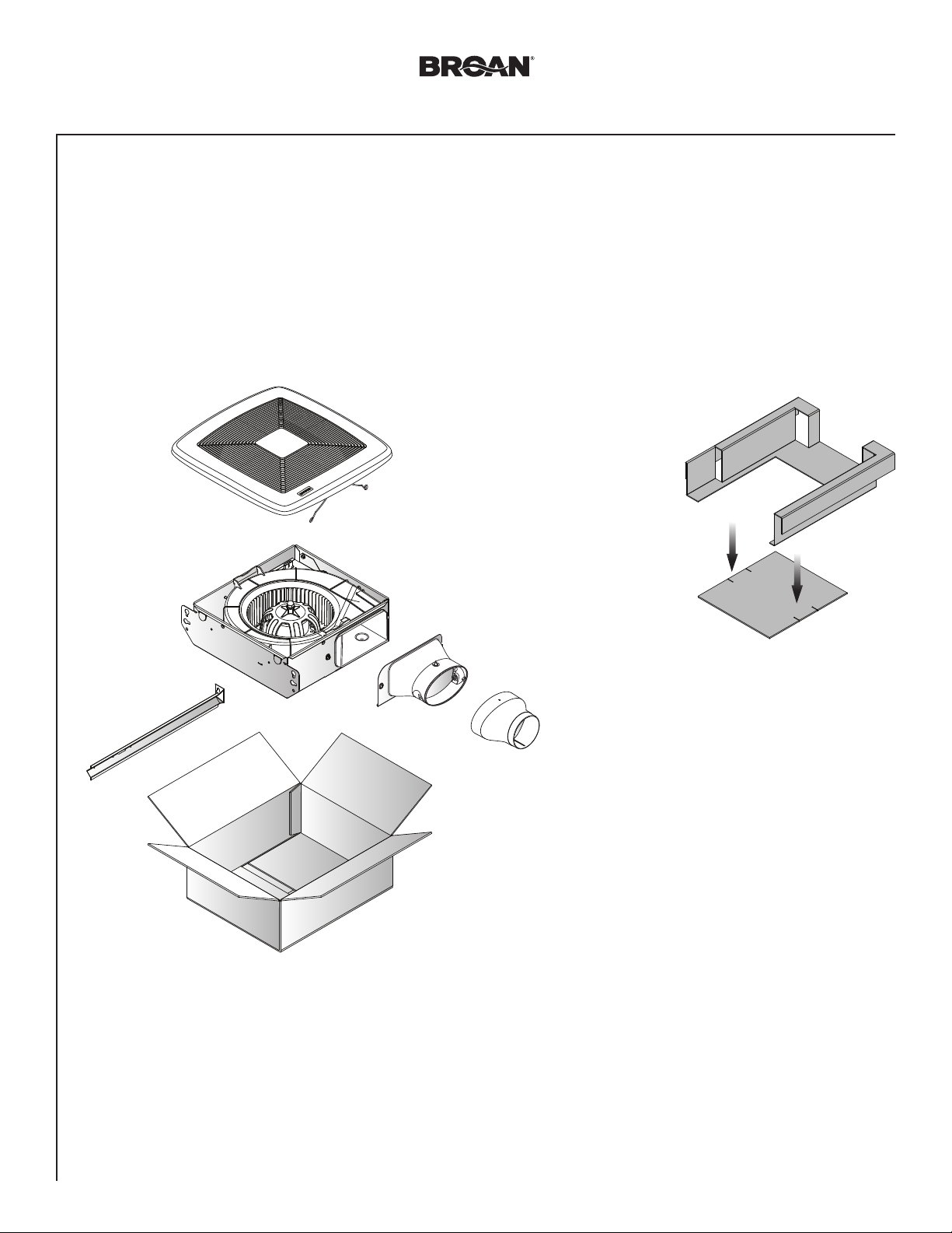
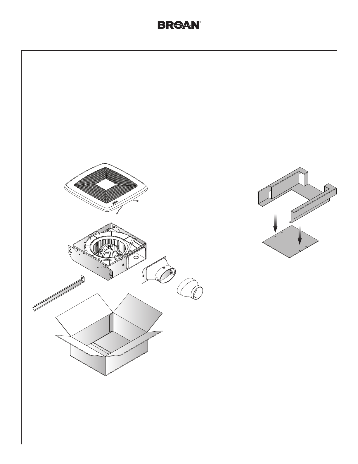
Remove from Packaging
1
Materials needed
• 4" round metal ducting recommended for best performance.
Use of other ducting is acceptable but may impact performance.
• Roof cap or wall cap (built-in damper recommended)
• Tape to seal duct connections
• Drywall screws, sheet metal screws or wire
• Electrical wiring and supplies per local code requirements
Punch out Mask
from packaging.
See Step 5.
4-in. to 3-in.
Reducer
(LP80 only)

Page 4
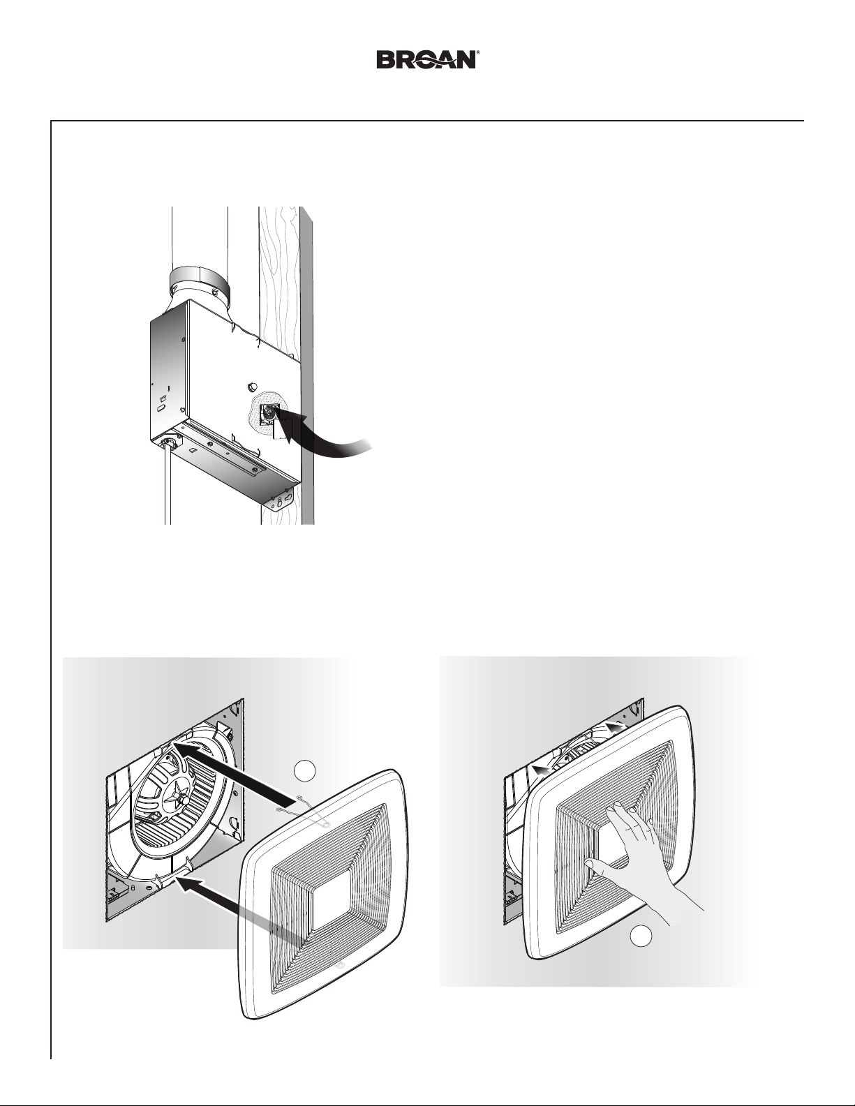
2
Installation
Install in Wall or Ceiling
2
UP
1
LP80 & LP110
(3 places)
n
Installation Guide
Wire
Install Ducting
3
Wall
2
2
Screw
through housing
on opposite side
1
- OR -
Ceiling
3
Tighten Screw into
housing to secure
4
mounting
1
Insert tab into slot
in housing.
2
4" Ducting
Tape
É
- OR -
3" Ducting
É
Tape
4" to 3"
Reducer
(LP80
É
only)
Tape

Page 5
Installation
Connect Wires
4
• Run 120VAC electrical wiring to the installation location.
• Use proper UL-approved connectors to secure wiring to the Knockout Plate.
• Connect wires as shown in wiring diagram.
1
3
Connect
wires
Attach cable
clamp to Knockout
2
Plate. Knockout
Plate may be
oriented as
desired.
LP80 & LP110
n
Installation Guide
4
ON/OFF
SWITCH
BLK
120 VAC
LINE IN
(purchase separately)
WHT
GRD
BLACK
WHITE
ON/OFF
SWITCH
BLK BLK
WHT
GRD
GROUND (green or bare)
SWITCH BOX
UNITSWITCH BOX
KNOCKOUT
PLATE
M
RECEPTACLE
WHT
120 VAC LINE IN

Page 6
Installation
Insert Mask and Finish Wall or Ceiling
5
Use this mask to prevent constru ction dust, drywa ll spray,
or paint from damaging insid e of product.
REMOVE MASK BEFORE INSTALLI NG GRILLE.
Utiliser ce couvercle pour e mpêcher la poussière d e construction,
le plâtre ou la peinture d’endomm ager l’intérieur du produit .
ENLEVER LE COUVERCLE AVANT D’I NSTALLER LA GRILLE.
Utilice esta cubiert a para
prevenir daños al interior
del producto debidos
a polvo de construcción ,
rociado en el panel de
yeso o pintura.
RETIRE LA CUBIERTA ANTE S
DE INSTALAR LA REJILL A.
Mask protects unit
during construction.
79350207A
Remove before
installing Grille.
LP80 & LP110
n
Installation Guide
Install Grille
6
Squeeze
grille springs
and insert
into slots
in housing.
1
2

Page 7
LP80 & LP110
n
Installation Guide
Operation
To Operate Fan
Use an ON/OFF switch or speed control to operate this
ventilator.
WARNING Before servicing or cleaning unit,
switch power off at service panel and lock the service
disconnecting means to prevent power from being
switched on accidentally. When the service disconnecting
means cannot be locked, securely fasten a prominent
warning device, such as a tag, to the service panel.
Cleaning and Maintenance
To Clean
For quiet and efficient operation, long life and attractive
appearance, remove Grille and vacuum interior of unit with
a dusting brush attachment.
The Motor is permanently lubricated and never needs
oiling. If the motor bearings are making excessive or
unusual noises, replace the Motor.
Troubleshooting
Symptom: The fan does not run.
• Check for an open fuse or circuit breaker in the building’s
service panel.
• Check that the plug-in connection for the Motor is seated
firmly in place.
• Check that the Blower Wheel spins freely.
Symptom: The fan runs erratically.
• Check that the Blower Wheel is firmly attached to the
Motor shaft and both spin freely.
Symptom: The fan seems noisy.
• Check that the back draft damper in the fan’s Duct
Connector pivots freely. Screws used to attach the
ducting to the Duct Connector may be preventing the
damper from opening.
• Check that the back draft damper in the wall or roof cap
pivots freely. These dampers are sometimes mistakenly
painted shut or obstructed by bird and insect debris.

Page 8
LP80 & LP110
n
Installation Guide
Service Parts
6
1
8
5
7
Key No. Part No. Description
1 77001277 Duct Connector Assembly
2 79140014 Grille Spring (2 included)
3 77001280 Grille Assembly (includes 2 grille springs)
4 77001297 Capacitor (LP80)
1100050 Capacitor (LP110)
5 77001298 Wire Panel Assembly
6 79110158 4” to 3” Reducer (LP80 only)
7 77001299 Hanger Bar
8 77001300 Knockout Plate
9 97020043 Blower Assembly (LP80)
1100048 Blower Assembly (LP110)
4
9
2
3
Warranty
BROAN ONE YEAR LIMITED WARRANTY
Broan warrants to the original consumer purchaser of its
products that such products will be free from defects in materials
or workmanship for a period of one year from the date of original
purchase. THERE ARE NO OTHER WARRANTIES, EXPRESS
OR IMPLIED, INCLUDING, BUT NOT LIMITED TO, IMPLIED
WARRANTIES OF MERCHANTABILITY OR FITNESS FOR A
PARTICULAR PURPOSE.
During this one-year period, Broan will, at its option, repair or
replace, without charge, any product or part which is found to be
defective under normal use and service.
THIS WARRANTY DOES NOT EXTEND TO FLUORESCENT
LAMP STARTERS, TUBES, HALOGEN AND INCANDESCENT
BULBS, FUSES, FILTERS, DUCTS, ROOF CAPS, WALL
CAPS AND OTHER ACCESSORIES FOR DUCTING. This
warranty does not cover (a) normal maintenance and service
or (b) any products or parts which have been subject to misuse,
negligence, accident, improper maintenance or repair (other
than by Broan), faulty installation or installation contrary to
recommended installation instructions.
The duration of any implied warranty is limited to the one-year
period as specified for the express warranty. Some states do not
allow limitation on how long an implied warranty lasts, so the
above limitation may not apply to you.
BROAN’S OBLIGATION TO REPAIR OR REPLACE, AT
BROAN’S OPTION, SHALL BE THE PURCHASER’S SOLE
AND EXCLUSIVE REMEDY UNDER THIS WARRANTY.
BROAN SHALL NOT BE LIABLE FOR INCIDENTAL,
CONSEQUENTIAL OR SPECIAL DAMAGES ARISING
OUT OF OR IN CONNECTION WITH PRODUCT USE OR
PERFORMANCE. Some states do not allow the exclusion or
limitation of incidental or consequential damages, so the above
limitation or exclusion may not apply to you.
This warranty gives you specific legal rights, and you may also
have other rights, which vary from state to state. This warranty
supersedes all prior warranties.
To qualify for warranty service, you must (a) notify Broan at the
address or telephone number below, (b) give the model number
and part identification and (c) describe the nature of any defect
in the product or part. At the time of requesting warranty service,
you must present evidence of the original purchase date.
Broan
926 W. State Street, Hartford, Wisconsin 53027
www.broan.com 800-558-1711
Order replacement parts by Part No., not by Key No.
99045483B

LIRE CES DIRECTIVES ET LES CONSERVER
Installateur : veuillez laisser ce guide au propriétaire.
Enregistrez votre produit en ligne à : www.broan.com/register.
LP80 et LP110
Ventilateur à
profil surbaissé
GUIDE D’INSTALLATION
Installation facile
© 2018 Broan
Table des matières
Avertissements et mises en garde 10
Installation type 10
Installation 11-14
Fonctionnement 15
Nettoyage et entretien 15
Dépannage 15
Pièces de rechange 16
Garantie 16

Page 10
LP80 et LP110
n
Guide d’installation
AVERTISSEMENT
OBSERVEZ LES DIRECTIVES CI-DESSOUS AFIN DE RÉDUIRE
LES RISQUES D’INCENDIE, DE CHOC ÉLECTRIQUE OU DE
BLESSURES CORPORELLES :
1. N’utilisez cet appareil que de la manière prévue par le fabricant.
Si vous avez des questions, communiquez avec le fabricant à
l’adresse ou au numéro de téléphone indiqués dans la garantie.
2.
Avant de procéder à l’entretien ou au nettoyage de l’appareil, coupez
l’alimentation du panneau électrique et verrouillez l’interrupteur
principal afin d’empêcher que le courant ne soit accidentellement
rétabli. S’il est impossible de verrouiller l’interrupteur principal,
fixez solidement un message d’avertissement, par exemple une
étiquette, sur le panneau électrique.
3. La pose de l’appareil et les travaux d’électricité doivent être
effectués par des personnes qualifiées conformément à la
réglementation en vigueur, notamment les normes de la
construction ayant trait à la protection contre les incendies.
4. Pour éviter les refoulements, l’apport d’air doit être suffisant pour
brûler les gaz produits par les appareils à combustion et les
évacuer dans le conduit de fumée (cheminée). Respectez les
directives du fabricant de l’appareil de chauffage et les normes
de sécurité, notamment celles publiées par la National Fire
Protection Association (NFPA), l’American Society for Heating,
Refrigeration and Air Conditioning Engineers (ASHRAE) et les
codes des autorités locales.
5. Veillez à ne pas endommager le câblage électrique ou d’autres
équipements non apparents lors de la découpe ou du perçage
du mur ou du plafond.
6. Les ventilateurs canalisés doivent toujours rejeter l’air à
l’extérieur.
7. Cet appareil peut être installé au-dessus d’une baignoire ou
d’une douche (uniquement dans le plafond) s’il est branché sur
un circuit de dérivation protégé par un disjoncteur de fuite à la
terre.
8. Cet appareil doit être relié à une mise à la terre.
ISOLANT* (Peut être
placé sur le boîtier de
ventilateur et autour.)
Installation type
BOÎTIER DE
VENTILATEUR
ATTENTION
1. Pour ventilation générale uniquement. N’utilisez pas
cet appareil pour évacuer des matières ou des vapeurs
dangereuses ou explosives.
2. Lorsque installé dans un mur ou un plafond en pente, le
raccord du conduit doit être tourné vers le haut.
3. Pour éviter d’endommager les roulements de moteur,
de déséquilibrer les pales ou de les rendre bruyantes,
débarrassez l’appareil de la poussière de plâtre, de
construction, etc.
4. Veuillez lire l’étiquette de spécifications du produit pour obtenir
plus de renseignements, notamment sur les exigences.
NE PAS INSTALLER DANS UNE ZONE DE CUISSON
Ne pas installer au-dessus ou à l’intérieur
de cette zone
45° 45°
Appareil
de cuisson
Plancher
CAPUCHON
DE TOIT*
(avec clapet
intégré)
• Se fixe aux montants de 2 po x 4 po
ou plus des murs ou aux solives du
plafond.
Solives Solives en I Fermes
Les conduits allant de ce ventilateur jusqu’à l’extérieur de l’habitation ont une grande influence sur le débit d’air, le bruit
du ventilateur et sa consommation d’énergie. Pour obtenir le meilleur rendement, utilisez les conduits les plus courts et
les plus droits que possible et évitez d’utiliser des conduits plus petits que ceux recommandés. L’isolation des conduits
peut contribuer à réduire les pertes d’énergie et éviter la prolifération de moisissures. Les ventilateurs installés sur
d’anciens conduits pourraient ne pas produire leur débit d’air nominal.
Pour un rendement optimal, il est recommandé d’utiliser des conduits métalliques ronds de 10 cm (4 po) de diamètre.
CÂBLE
D’ALIMENTATION*
Scellez l’écart
autour du boîtier.
CONDUIT ROND*
*Vendu
séparément.
OR
Scellez les
joints avec
du ruban
à conduit.
INSTALLATION DANS UN PLAFOND
COUDES
RONDS*
Utilisez des
conduits les
plus courts
possible.
CAPUCHON
MURAL* (avec
clapet intégré)

Pa g e 11
Installation
LP80 et LP110
n
Guide d’installation
Outils requis
• Tournevis électrique à pointe cruciforme
• Tournevis cruciforme
• Pince à dénuder les fils
• Pince coupante
Sortir de l’emballage
1
Matériel requis
• Conduit rond de 10,2 cm (4 po) recommandé pour un meilleur
rendement. D’autres types de conduits sont acceptables mais
peuvent affecter le rendement.
• Capuchon de toit ou mural (clapet intégré recommandé)
• Ruban pour sceller les raccords du conduit
• Vis à cloisons sèches, vis à tôle ou suspendre
• Fils électriques et fournitures conformes au code local
Détacher le masque
de l’emballage.
Voir étape 5.
Réducteur de
10,2 cm à 7,6 cm
(4 po à 3 po)
(LP80 seulement)

Page 12
2
Installation
Installer dans le mur ou le plafond
2
HAUT
1
LP80 et LP110
(en 3 points)
n
Guide d’installation
Suspendre
Installer le conduit
3
1
Mur
2
2
2
Vis à travers le
boîtier du côté
opposé
1
Conduit
de 10,2 cm
(4 po)
- OU -
4
Plafond
Réducteur de
10,2 cm à 7,6 cm
(4 po à 3 po)
(LP80 seulement)
3
Serrer la vis dans le
boîtier pour assurer
le montage
Conduit
de 7,6 cm
(3 po)
É
Ruban
Insérer la languette
dans la fente du boîtier.
Ruban
É
- OU -
É
Ruban

Page 13
Installation
Connecter les fils
4
• Acheminer un fil électrique de 120 VCA jusqu’au site d’installation.
• Utiliser les connecteurs homologués UL pour fixer le fil à l’ouverture préamorcée fournie.
• Connecter les fils, tel qu’illustré dans le schéma de câblage.
1
3
Connecter
les fils
Fixer la pince du
câble à l’ouverture
2
préamorcée. La
plaque peut être
orientée dans le
sens voulu.
LP80 et LP110
n
Guide d’installation
4
INTERRUPTEUR
NOIR
ENTRÉE
120 VCA
INTERRUPTEUR
(vendu séparément)
BLANC
TERRE
NOIR
BLANC
NOIR NOIR
BLANC
TERRE
FIL DE TERRE (vert ou fil nu)
BOÎTE
D'INTERRUPTEUR
M
APPAREILBOÎTE D'INTERRUPTEUR
OUVERTURE
PRÉAMORCÉE
BLANC
PRISE
ALIMENTATION 120 VCA
Page 14
Installation
Insérer le masque et finir le mur ou le plafond
5
Use this mask to prevent constru ction dust, drywa ll spray,
or paint from damaging insid e of product.
REMOVE MASK BEFORE INSTALLI NG GRILLE.
Utiliser ce couvercle pour e mpêcher la poussière d e construction,
le plâtre ou la peinture d’endomm ager l’intérieur du produit .
ENLEVER LE COUVERCLE AVANT D’I NSTALLER LA GRILLE.
Utilice esta cubiert a para
prevenir daños al interior
del producto debidos
a polvo de construcción ,
rociado en el panel de
yeso o pintura.
RETIRE LA CUBIERTA ANTE S
DE INSTALAR LA REJILL A.
Ce masque protège
79350207A
l’appareil durant la
construction. Le retirer
avant d’installer la grille.
LP80 et LP110
n
Guide d’installation
Installer la grille
6
Pincer les ressorts
de la grille et les
insérer dans les
fentes du boîtier.
1
2

Page 15
LP80 et LP110
n
Guide d’installation
Fonctionnement
Pour actionner le ventilateur
Utilisez un interrupteur marche/arrêt ou une commande de
vitesse pour actionner le ventilateur.
AVERTISSEMENT
à l’entretien ou au nettoyage de l’appareil, coupez
l’alimentation du panneau électrique et verrouillez
l’interrupteur principal afin d’empêcher que le courant
ne soit accidentellement rétabli. S’il est impossible de
verrouiller l’interrupteur principal, fixez solidement un
message d’avertissement, par exemple une étiquette,
sur le panneau électrique.
Avant de procéder
Nettoyage et entretien
Pour nettoyer
Pour un fonctionnement silencieux et efficace, ainsi qu’une
durabilité et une apparence supérieures, enlevez la grille
et nettoyez l’intérieur de l’appareil avec un aspirateur muni
d’une brosse à épousseter.
Le moteur est lubrifié en permanence et n’a pas
besoin d’être huilé. Si les roulements du moteur sont
anormalement bruyants, remplacez le moteur.
Dépannage
Symptôme : Le ventilateur ne démarre pas.
• Vérifiez que le disjoncteur ou le fusible ne sont pas
coupés dans le panneau électrique de l’édifice.
• Vérifiez que la fiche du moteur est bien branchée et
fermement appuyée.
• Vérifiez que la roue à ailettes tourne librement.
Symptôme : Le ventilateur tourne de manière inégale.
• Vérifiez que la roue à ailettes est solidement fixée à
l’arbre du moteur et que les deux tournent librement.
Symptôme : Le ventilateur semble bruyant.
• Vérifiez que le clapet à l’arrière du raccord de conduit
pivote librement. Les vis utilisées pour fixer le conduit
au raccord peuvent empêcher le clapet de s’ouvrir
correctement.
• Vérifiez que le clapet antirefoulement du capuchon mural
ou de toit pivote librement. Ces clapets sont parfois peints
par erreur, ce qui les empêche de s’ouvrir, ou obstrués par
des débris d’oiseaux ou d’insectes.

Page 16
LP80 et LP110
n
Guide d’installation
Pièces de rechange
6
1
8
5
7
N° de repère N° de pièce Description
1 77001277 Ensemble de raccord de conduit
2 79140014 Ressort de grille (2 inclus)
3 77001280 Ensemble de grille (comprend
4 77001297 Condensateur (LP80)
1100050 Condensateur (LP110)
5 77001298 Ensemble de panneau de câblage
6 79110158 Réducteur de 10,2 cm à 7,6 cm
7 77001299 Tige de suspension
8 77001300 Plaque à ouverture préamorcée
9 97020043 Ensemble de ventilateur (LP80)
1100048 Ensemble de ventilateur (LP110)
Veuillez commander les pièces par N° de pièce et non par N° de
repère.
4
9
2
3
2 ressorts)
(4 po à 3 po) (LP80 seulement)
Garantie
GARANTIE LIMITÉE D’UN AN BROAN
Broan garantit à l’acheteur original que les produits vendus
en vertu de la présente sont libres de tout vice de matériau ou
de fabrication pour une période d’un an à compter de la date
d’achat originale. CETTE GARANTIE NE COMPORTE AUCUNE
AUTRE GARANTIE, EXPRESSE OU TACITE, Y COMPRIS,
MAIS SANS S’Y LIMITER, LES GARANTIES TACITES DE
VALEUR MARCHANDE OU D’ADAPTATION À UN USAGE
PARTICULIER.
Durant cette période d’un an, Broan réparera ou remplacera
gratuitement, à sa discrétion, tout produit ou toute pièce jugés
défectueux dans des conditions normales d’utilisation.
CETTE GARANTIE NE S’APPLIQUE PAS AUX TUBES
FLUORESCENTS ET AUX DÉMARREURS, NI AUX AMPOULES
HALOGÈNES OU INCANDESCENTES, FUSIBLES, FILTRES,
CONDUITS, CAPUCHONS DE TOIT, CAPUCHONS MURAUX
ET AUTRES ACCESSOIRES POUR CONDUITS. Cette garantie
ne couvre pas (a) les frais d’entretien ou de service normaux ni
(b) tout produit ou toute pièce soumis à un abus, une négligence,
un accident, un entretien ou une réparation inadéquats (autres
que ceux effectués par Broan), une mauvaise installation ou
une installation contraire aux instructions recommandées.
La durée de toute garantie tacite est limitée à la période d’un
an stipulée pour la garantie expresse. Certains territoires ou
provinces interdisant de limiter la durée d’une garantie tacite,
la limitation ci-dessus peut ne pas s’appliquer à votre situation.
L’OBLIGATION POUR BROAN DE RÉPARER OU DE
REMPLACER LE PRODUIT, À SA DISCRÉTION, CONSTITUE
LE SEUL RECOURS DE L’ACHETEUR EN VERTU DE LA
PRÉSENTE GARANTIE. BROAN NE PEUT ÊTRE TENUE
RESPONSABLE DES DOMMAGES INDIRECTS OU
CONSÉCUTIFS NI DES DOMMAGES-INTÉRÊTS PARTICULIERS
DÉCOULANT DE L’UTILISATION OU DU RENDEMENT DU
PRODUIT. Certains territoires ou provinces ne permettant pas la
limitation ou l’exclusion des dommages indirects ou consécutifs,
la limitation ci-dessus peut ne pas s’appliquer à votre situation.
La présente garantie vous confère des droits spécifiques
reconnus par la loi. D’autres droits pourraient également vous
être accordés selon la législation locale en vigueur. La présente
garantie remplace toutes les autres garanties précédentes.
Pour vous prévaloir de cette garantie, vous devez (a) aviser
Broan à l’adresse ou au numéro de téléphone indiqués cidessous, (b) donner le numéro de modèle du produit et le
numéro d’identification de la pièce et (c) décrire la nature de la
défectuosité du produit ou de la pièce. Lors de votre demande
de garantie, vous devez présenter une preuve de la date d’achat
originale.
Broan
926 W. State Street, Hartford, Wisconsin 53027
www.broan.com 800-558-1711
99045483B

LEA Y CONSERVE ESTAS INSTRUCCIONES
Aviso al instalador: deje esta guía con el dueño de la casa.
Registre su producto en línea en www.broan.com/register.
LP80 y LP110
Ventilador de
bajo perfil
GUÍA DE INSTALACIÓN
Instalación sencilla
© 2018 Broan
Índice
Advertencias y precauciones 18
Instalación típica 18
Instalación 19-22
Funcionamiento 23
Limpieza y mantenimiento 23
Resolución de problemas 23
Piezas de servicio 24
Garantía 24

Página 18
LP80 y LP110
n
Guía de instalación
ADVERTENCIA
PARA REDUCIR EL RIESGO DE INCENDIOS, DESCARGAS
ELÉCTRICAS O LESIONES PERSONALES, SIGA LAS
SIGUIENTES PRECAUCIONES:
1. Use la unidad sólo de la manera indicada por el fabricante. Si
tiene preguntas, comuníquese con el fabricante a la dirección o
al número telefónico que se incluye en la garantía.
2. Antes de dar servicio a la unidad o de limpiarla, interrumpa el
suministro eléctrico en el panel de servicio y bloquee los medios
de desconexión del servicio para evitar que la electricidad se
reanude accidentalmente. Cuando no sea posible bloquear los
medios de desconexión del servicio, fije firmemente una señal
de advertencia (como una etiqueta) en un lugar visible del panel
de servicio.
3. Una o más personas calificadas deben realizar el trabajo de
instalación y el cableado eléctrico, de acuerdo con todos los
códigos y normas correspondientes, incluidos los códigos y
las normas de construcción específicos de protección contra
incendios.
4. Es necesario suficiente aire para que se lleve a cabo una
combustión y una extracción adecuadas de los gases a través
del tubo de humos (chimenea) del equipo quemador de
combustible, con el fin de evitar el contratiro. Siga las directrices
y las normas de seguridad del fabricante del equipo de
calefacción, como las publicadas por la Asociación Nacional de
Protección contra Incendios (National Fire Protection Association,
NFPA), la Sociedad Americana de Ingenieros de Calefacción,
Refrigeración y Aire Acondicionado (American Society for
Heating, Refrigeration and Air Conditioning Engineers, ASHRAE)
y las autoridades normativas locales.
5. Al cortar o perforar a través de la pared o del techo, tenga cuidado
de no dañar el cableado eléctrico ni otros servicios ocultos.
6. Los ventiladores en conductos siempre deben ventearse hacia el
exterior.
7. Esta unidad puede instalarse sobre una tina o ducha (en el cielo
raso solamente) siempre que se conecte a un GFCI (interruptor
accionado por pérdida de conexión a tierra) en un circuito de
derivación protegido.
8. Esta unidad debe estar conectada a tierra.
AISLAMIENTO* (Coloque
alrededor y sobre la
cubierta del ventilador).
CUBIERTA DEL
VENTILADOR
PRECAUCIÓN
1. Sólo para usarse como medio de ventilación general. No debe
usarse para la extracción de materiales o vapores peligrosos o
explosivos.
2. Cuando se instale en una pared o un cielo raso con
pendiente, el conector del conducto debe apuntar hacia arriba.
3. Para evitar daños a los cojinetes del motor y rotores ruidosos
o desbalanceados, mantenga la unidad de potencia protegida
contra rociados de yeso, polvos de construcción, etc.
4. Lea la etiqueta de especificaciones del producto para ver
información y requisitos adicionales.
NO USAR EL PRODUCTO EN UN ÁREA DE COCINA
No instale el equipo sobre o dentro de esta área.
45° 45°
Equipo
de cocina
Piso
TAPA DE
TECHO* (con
regulador de
tiro integrado)
Instalación típica
• Se fija a vigas 2 x 4 pulg. o a
montantes de pared o viguetas de
cielo raso de mayor tamaño.
Viguetas Viguetas “I” Vigas
Los conductos desde este ventilador hacia el exterior del edificio tienen un gran efecto sobre el flujo de aire, el ruido y el uso de energía
del ventilador. Utilice el tramo de conductos más corto y recto posible para obtener un desempeño óptimo y evite instalar el ventilador
con conductos menores que los recomendados. El aislamiento alrededor de los conductos puede reducir la pérdida de energía e inhibir
el desarrollo de moho. Los ventiladores instalados en conductos existentes podrían no obtener el flujo de aire nominal.
Para un mejor desempeño, se recomienda utilizar conductos metálicos redondos y rígidos de 4 pulg. (10 cm).
CABLE
ELÉCTRICO*
Selle las
separaciones
alrededor de la
cubierta.
CONDUCTO
REDONDO*
*Se compra
por separado.
Selle con
cinta las
uniones
de los
conductos.
SE MUESTRA LA INSTALACIÓN EN EL CIELO RASO
OR
OR
CODOS
REDONDOS*
Mantenga
cortos los
tramos de
conductos.
TAPA DE
PARED* (con
regulador de
tiro integrado)
Página 19
Instalación
LP80 y LP110
n
Guía de instalación
Herramientas necesarias
• Destornillador eléctrico con punta Phillips
• Destornillador Phillips
• Desforrador de aislamiento de cables
• Cortador de cables
Retire del empaque
1
Materiales necesarios
• Se recomienda el conducto metálico redondo de 4 pulg. (10.2 cm)
para obtener el mejor desempeño. Es aceptable usar otros conductos,
pero se puede afectar el desempeño.
• Tapa de techo o tapa de pared (se recomienda el regulador integrado)
• Cinta para sellar las conexiones de los conductos
• Tornillos para placa de yeso, para chapa metálica o cable
• Cableado eléctrico y suministros de acuerdo con los requisitos del
código local
Perfore la cubierta
del empaque.
Vea el paso 5.
Reductor de
4 a 3 pulg.
(10.2 a 7.6 cm)
(LP80 solamente)

Página 20
2
Instalación
Instale en la pared o el cielo raso
2
ARRIBA
1
LP80 y LP110
n
Guía de instalación
Cable
(3 lugares)
Pared
Instale los conductos
3
1
2
2
2
Tornillo a través de
la cubierta al lado
opuesto
1
Conducto
de 4 pulg.
(10.2 cm)
- O BIEN -
4
Cielo raso
Reductor de
4 a 3 pulg.
(10.2 a 7.6 cm)
(LP80
solamente)
É
- O
3
Apriete el tornillo
en la caja para
asegurar el
montaje
Conducto
de 3 pulg.
(7.6 cm)
É
Cinta
É
Inserte la pestaña en
la ranura de la cubierta.
Cinta
BIEN -
Cinta

Página 21
Instalación
Conecte los cables
4
• Coloque el cable eléctrico de 120 VCA hasta el lugar de la instalación.
• Use conectores adecuados y aprobados por UL para asegurar el cableado a la placa de agujero ciego.
• Conecte los cables tal como se ilustra en el diagrama de cableado.
1
3
Conecte
los cables
Fije la abrazadera del
2
cable a la placa de
agujero ciego. La placa de
agujero ciego se puede
orientar como se desee.
LP80 y LP110
n
Guía de instalación
4
INTERRUPTOR
DE ENCENDIDO/
APAGADO
NEGRO
LÍNEA DE
ENTRADA
DE 120 VCA
INTERRUPTOR DE
ENCENDIDO/APAGADO
(se compra por separado)
BLANCO
TIERRA
NEGRO
BLANCO
NEGRO NEGRO
BLANCO
TIERRA
TIERRA (verde o desnudo)
CAJA DEL
INTERRUPTOR
M
UNIDADCAJA DEL INTERRUPTOR
PLACA DE
AGUJERO CIEGO
BLANCO
RECEPTÁCULO
LÍNEA DE ENTRADA DE 120 VCA

Página 22
LP80 y LP110
n
Instalación
Inserte la cubierta protectora y dé acabado a la pared o al cielo raso
5
Use this mask to prevent constru ction dust, drywa ll spray,
or paint from damaging insid e of product.
REMOVE MASK BEFORE INSTALLI NG GRILLE.
Utiliser ce couvercle pour e mpêcher la poussière d e construction,
le plâtre ou la peinture d’endomm ager l’intérieur du produit .
ENLEVER LE COUVERCLE AVANT D’I NSTALLER LA GRILLE.
Utilice esta cubiert a para
prevenir daños al interior
del producto debidos
a polvo de construcción ,
rociado en el panel de
yeso o pintura.
RETIRE LA CUBIERTA ANTE S
DE INSTALAR LA REJILL A.
La cubierta protectora
protege la unidad durante
79350207A
la construcción. Quítela
antes de instalar la rejilla.
Guía de instalación
Instale la rejilla
6
Comprima los
resortes de la
rejilla e inserte
en las ranuras
de la cubierta.
1
2

Página 23
LP80 y LP110
n
Guía de instalación
Funcionamiento
Para accionar el ventilador
Para accionar este ventilador, utilice el interruptor de
encendido/apagado o el control de velocidad.
ADVERTENCIA Antes de realizar el
servicio o de limpiar la unidad, corte el suministro
eléctrico en el panel de servicio y bloquee el servicio
desconectando los medios que evitan que se conecte
la energía en forma accidental. Cuando no se puedan
bloquear los medios que desconectan el servicio,
coloque un dispositivo de alarma importante, como
por ejemplo una etiqueta, en el panel de servicio.
Limpieza y mantenimiento
Para limpiar
Para lograr un funcionamiento silencioso y eficiente, larga
vida y una apariencia atractiva, retire la rejilla y aspire
el interior de la unidad con el accesorio del cepillo para
sacudir polvo.
El motor está permanentemente lubricado y nunca
necesitará ponerle aceite. Si los cojinetes del motor hacen
ruidos excesivos o inusuales, reemplace el motor.
Resolución de problemas
Síntoma: el ventilador no funciona.
• Compruebe si hay un fusible o interruptor de circuitos
abierto en el panel de servicio del edificio.
• Compruebe que la conexión enchufable del motor esté
firmemente asentada en su lugar.
• Compruebe que la rueda del ventilador gira libremente.
Síntoma: el ventilador funciona erráticamente.
• Compruebe que la rueda del ventilador esté firmemente
acoplada al eje del motor y que ambas giren libremente.
Síntoma: el ventilador parece ruidoso.
• Compruebe que el regulador de contratiro en el conector
de conductos del ventilador pivotee libremente. Los
tornillos empleados para fijar el conducto al conector
podrían impedir que se abra el regulador.
• Compruebe que el regulador de contratiro en la pared
o tapa de techo pivotee libremente. A veces a estos
reguladores se les tapa con pintura por error, o están
obstruidos por desechos de aves e insectos.

Página 24
LP80 y LP110
n
Guía de instalación
Piezas de servicio
6
1
8
5
7
Clave N.º Pieza N.º Descripción
1 77001277 Conjunto del conector de conductos
2 79140014 Resorte de la rejilla (se incluyen 2)
3 77001280 Conjunto de la rejilla (incluye 2 resortes de la rejilla)
4 77001297 Capacitor (LP80)
1100050 Capacitor (LP110)
5 77001298 Conjunto del panel de cableado
6 79110158 Reductor de 4 a 3 pulg. (10.2 a 7.6 cm)
(LP80 solamente)
7 77001299 Barra de suspensión
8 77001300 Placa de agujero ciego
9 97020043 Conjunto del ventilador (LP80)
1100048 Conjunto del ventilador (LP110)
Pida las piezas por número de pieza, no por número de clave.
4
9
2
3
Garantía
GARANTÍA LIMITADA DE UN AÑO DE BROAN
Broan garantiza al consumidor comprador original de sus
productos que dichos productos estarán libres de defectos en
materiales o mano de obra durante un período de un año a partir de
la fecha de compra original. NO EXISTEN OTRAS GARANTÍAS,
EXPLÍCITAS O IMPLÍCITAS, INCLUYENDO, ENTRE OTRAS,
GARANTÍAS IMPLÍCITAS DE COMERCIALIZACIÓN O APTITUD
PARA UN PROPÓSITO PARTICULAR.
Durante este período de un año, Broan, a su criterio,
reparará o reemplazará sin cargo alguno cualquier pieza o
producto que se encuentre defectuoso bajo condiciones normales
de uso y servicio.
LA PRESENTE GARANTÍA NO CUBRE TUBOS O
ARRANCADORES DE LÁMPARAS FLUORESCENTES,
BOMBILLAS HALÓGENAS E INCANDESCENTES, FUSIBLES,
FILTROS, CONDUCTOS, TAPAS DE TECHO O DE PARED
Y DEMÁS ACCESORIOS DE CANALIZACIÓN. Esta garantía
no cubre (a) mantenimiento y servicio normales, ni (b) ningún
producto o piezas que se hayan sometido a uso inadecuado,
negligencia, accidente, mantenimiento o reparación inadecuada
(no hecha por Broan), instalación incorrecta o instalación en
contra de las instrucciones de instalación recomendadas.
La duración de cualquier garantía implícita se limita a un
período de un año, como se especifica en la garantía expresa.
Algunos estados no permiten limitaciones en cuanto al tiempo
de vencimiento de una garantía implícita, por lo que la limitación
antes mencionada podría no aplicarse a usted.
LA OBLIGACIÓN DE BROAN DE REPARAR O REEMPLAZAR,
A CRITERIO DE BROAN, SERÁ EL ÚNICO Y EXCLUSIVO
RECURSO DEL COMPRADOR BAJO ESTA GARANTÍA. BROAN
NO SERÁ RESPONSABLE POR DAÑOS INCIDENTALES,
RESULTANTES O ESPECIALES QUE SURJAN DEL USO
O DESEMPEÑO DEL PRODUCTO O EN RELACIÓN CON
ESTE. Algunos estados no permiten la exclusión o limitación de
daños incidentales o resultantes, por lo que la limitación antes
mencionada podría no aplicarse a usted.
Esta garantía le otorga derechos legales específicos, y usted
podría tener otros derechos que varían de un estado a otro.
Esta garantía sustituye todas las garantías anteriores.
Para tener derecho al servicio de la garantía, usted debe (a)
notificar a Broan NuTone a la dirección y número de teléfono
que aparecen abajo, (b) proporcionar el número de modelo
y la identificación de la pieza y (c) describir la naturaleza de
cualquier defecto en el producto o pieza. En el momento de
solicitar el servicio cubierto por la garantía, debe presentar un
comprobante de la fecha original de compra.
Broan
926 W. State Street, Hartford, Wisconsin 53027
www.broan.com 800-558-1711
99045483B
 Loading...