


PM250
PM250 SERIES
READ AND SAVE THESE INSTRUCTIONS
WARNING
TO REDUCE THE RISK OF FIRE, ELECTRIC SHOCK, OR INJURY
TO PERSONS, OBSERVE THE FOLLOWING:
1. Use this unit only in the manner intended by the manufacturer. If you
have questions, contact the manufacturer at the address or tele-
phone number listed in the warranty.
2. Before servicing or cleaning unit, switch power off at service panel
and lock service panel to prevent power from being switched on
accidentally. When the service disconnecting means cannot be
locked, securely fasten a prominent warning device, such as a tag,
to the service panel.
3. Installation work and electrical wiring must be done by a qualified
person(s) in accordance with all applicable codes and standards,
including fire-rated construction codes and standards.
4. Sufficient air is needed for proper combustion and exhausting of
gases through the flue (chimney) of fuel burning equipment to pre-
vent backdrafting. Follow the heating equipment manufacturer’s
guidelines and safety standards such as those published by the Na-
tional Fire Protection Association (NFPA), and the American Soci-
ety for Heating, Refrigeration and Air Conditioning Engineers
(ASHRAE), and the local code authorities.
5. When cutting or drilling into wall or ceiling, do not damage electrical
wiring and other hidden utilities.
6. Ducted fans must always be vented to the outdoors.
7. Do not use this unit with any separate solid-state speed control device.
8. To reduce the risk of fire, use only metal ductwork.
9. This unit must be grounded.
TO REDUCE THE RISK OF A RANGE TOP GREASE FIRE:
A. Never leave surface units unattended at high settings. Boilovers cause
smoking and greasy spillovers that may ignite. Heat oils slowly on
low or medium settings.
B. Always turn hood ON when cooking at high heat or when flambeing
food (i.e. Crepes Suzette, Cherries Jubilee, Peppercorn Beef
Flambe’).
C. Clean ventilating fans frequently. Grease should not be allowed to
accumulate on fan or filter.
D. Use proper pan size. Always use cookware appropriate for the size
of the surface element.
WARNING
TO REDUCE THE RISK OF INJURY TO PERSONS IN THE EVENT
OF A RANGE TOP GREASE FIRE, OBSERVE THE FOLLOWING:*
1. SMOTHER FLAMES with a close-fitting lid, cookie sheet, or metal
tray, then turn off the burner. BE CAREFUL TO PREVENT BURNS.
If the flames do not go out immediately, EVACUATE AND CALL
THE FIRE DEPARTMENT.
2. NEVER PICK UP A FLAMING PAN - You may be burned.
3. DO NOT USE WATER, including wet dishcloths or towels - violent
steam explosion will result.
4. Use an extinguisher ONLY if:
A. You know you have a Class ABC extinguisher and you already
know how to operate it.
B. The fire is small and contained in the area where it started.
C. The fire department is being called.
D. You can fight the fire with your back to an exit.
* Based on “Kitchen Fire Safety Tips” published by NFPA.
!
INTENDED FOR DOMESTIC COOKING ONLY
!
!
CAUTION
1. To reduce risk of fire and to properly exhaust air, be sure to duct air
outside. Do not vent exhaust air into spaces within walls or ceilings
or into attics, crawl spaces, or garages.
2. Take care when using cleaning agents or detergents.
3. Avoid using food products that produce flames under the Range
Hood.
4. For general ventilating use only. Do not use to exhaust hazardous
or explosive materials and vapors.
5. To avoid motor bearing damage and noisy and/or unbalanced
impellers, keep drywall spray, construction dust, etc. off power unit.
6. Your hood motor has a thermal overload which will automatically
shut off the motor if it becomes overheated. The motor will restart
when it cools down. If the motor continues to shut off and restart,
have the hood serviced.
7. For best capture of cooking impurities, the bottom of the hood should
be a minimum of 24" and a maximum of 30" above the cooking
surface.
8. Two installers are recommended.
9. Use with approved cord-connection kit only.
10. Please read specification label on product for further information
and requirements.
POWER
MODULE
NON-DUCTED RECIRCULATION FILTER
INSTALLATION
1. Remove the metal wires (Fig. 7) and discard them.
2. Install the Non-ducted recirculation Filter over the grease filter and
secure it with the metal wires supplied with the Non-ducted
recirculation Filter (Fig. 4).
WIRING
Note: This range hood must be properly grounded.
The unit should be installed by a qualified electrician in accor-
dance with all applicable national and local electrical codes.
Secure the conduit to the upper wiring hole through a conduit
connector.
Remove the (2) screws of the lateral wiring field cover and make
electrical connections. Connect both white leads to white supply lead
using suitable connector, connect black to black and green to green.
OPERATION
Controls
Light switch: turns the lamps on and off.
Blower switch: makes it possible to select the motor operating speed.
Position 0: motor off; Position I: motor lower speed; Position II: motor
high speed.
NON-DUCTED
RECIRCULATION
FILTER
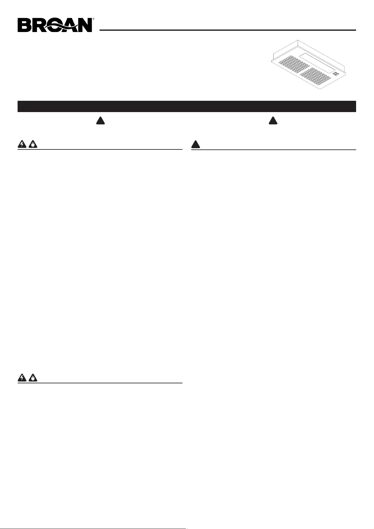
INSTALL THE DUCTWORK
NOTE: To reduce the risk of fire, use only metal ductwork.
1. Decide where the ductwork will run between the hood and the
outside.
2. A straight, short duct run will allow the hood to perform most
efficiently.
3. Long duct runs, elbows, and transitions will reduce the performance
of the hood. Use as few of them as possible. Larger ducting may
be required for best performance with longer duct runs.
4. Install a roof or wall cap. Connect round metal ductwork to cap
and work back towards hood location. Use duct tape to seal the
joints between ductwork sections.
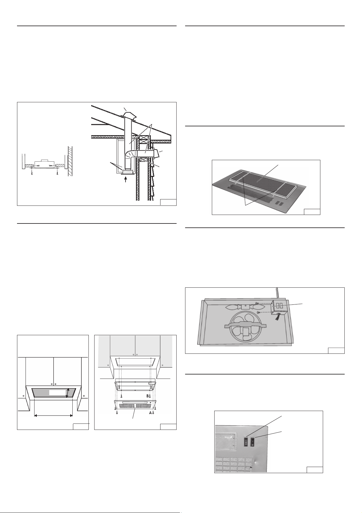
INSTALL THE HOOD
NOTE: the hood has to be installed, inside the cabinet, at minimum
1” from the rear wall cabinet and at 3” from the front wall cabinet.
The internal height of cabinet has to be minimum 16”.
The hood should be mounted centered over the cook top burners.
1. Cut a hole in the bottom of the cabinet, using the dimensions shown
in Fig. 2.
2. Take off the (4) “A” screws and remove the metal grid (Fig. 3).
3. NOTE: For installations where the Power Pack is less than 30”
above cook top, it is recommended that the Power Pack be
mounted into a metal liner or non-combustible material. This will
allow easier cleaning and provide protection to the cabinetry.
4. Insert the hood in the cabinet and secure with the (4) “B” mounting
screws 3.2x13mm (Fig. 3). For alternative side fixing use M4x15mm
screws with washers and nuts.
5. In the Non-Ducted Recirculation Configuration, install the Non-
ducted recirculation Filter before replacing the grid (see section
“Non-ducted recirculation filter installation”).
6. Replace the grid after wiring is completed.
ROOF CAP
ROUND
DUCT
POWER
MODULE
WALL
CAP
7”
ROUND
ELBOW
24” TO 30” ABOVE
COOKING SURFACE
10-1/4”
CUT A HOLE IN THE BOTTOM OF
THE CABINET
19-1/2”
GRID
LIGHT SWITCH
BLOWER SWITCH
FIG. 1
FIG. 2
FIG. 3
FIG. 4
FIG. 6
METAL WIRES
CONNECT DUCTWORK
Ducted Configuration
1. Use 7" round metal duct to connect the discharge collar on the
hood to the ductwork above. An optional 7” round damper may
be used (purchased seperately).
2. Use duct tape to make all joints secure and air tight.
Non-Ducted Recirculation Configuration
1. Connect a 7” round metal duct to the discharge opening so
that the air is sent outside the cabinet and sent back into the
room.
2. Use duct tape to make all joints secure and air tight.
LATERAL
WIRING FIELD
COVER
FIG. 5
MAINTENANCE
ALWAYS SWITCH OFF THE ELECTRICITY SUPPLY BEFORE
CARRYING OUT ANY OPERATIONS ON THE APPLIANCE.
Grease Filter
The grease filter should be cleaned frequently. Use a warm detergent
solution. Grease filter is dishwasher safe.
To remove the grease filter: remove the (4) screws and take off the
metal grid. Take off the metal wires and remove the grease filter.
Non-Ducted Recirculation Filter
The Non-Ducted Recirculation filter should be changed every 6
months.
To remove the Non-Ducted Recirculation filter:
1. Remove the grid taking off the (4) “A” screws 3.9x6mm (Fig. 3).
2. Remove the metal wires (Fig. 4) and replace the Non-ducted
recirculation Filter.
Cleaning
Occasional care will help preserve its fine appearance.
• Clean with warm water and mild detergent only.
• Follow all cleaning by rinsing with clear water.
• Wipe dry with clean, soft cloth.
Light bulbs
This range hood requires two 40-Watt light bulbs (not included).
To change bulbs:
1. Remove the 2.9x9.5mm screw securing the light fitting.
2. Pull down lens to remove.
3. Replace with light bulbs of the same type (MAX 40W, 120V,
E12, Type B or Type T8 Bulb). CAUTION: BULB MAY BE HOT!
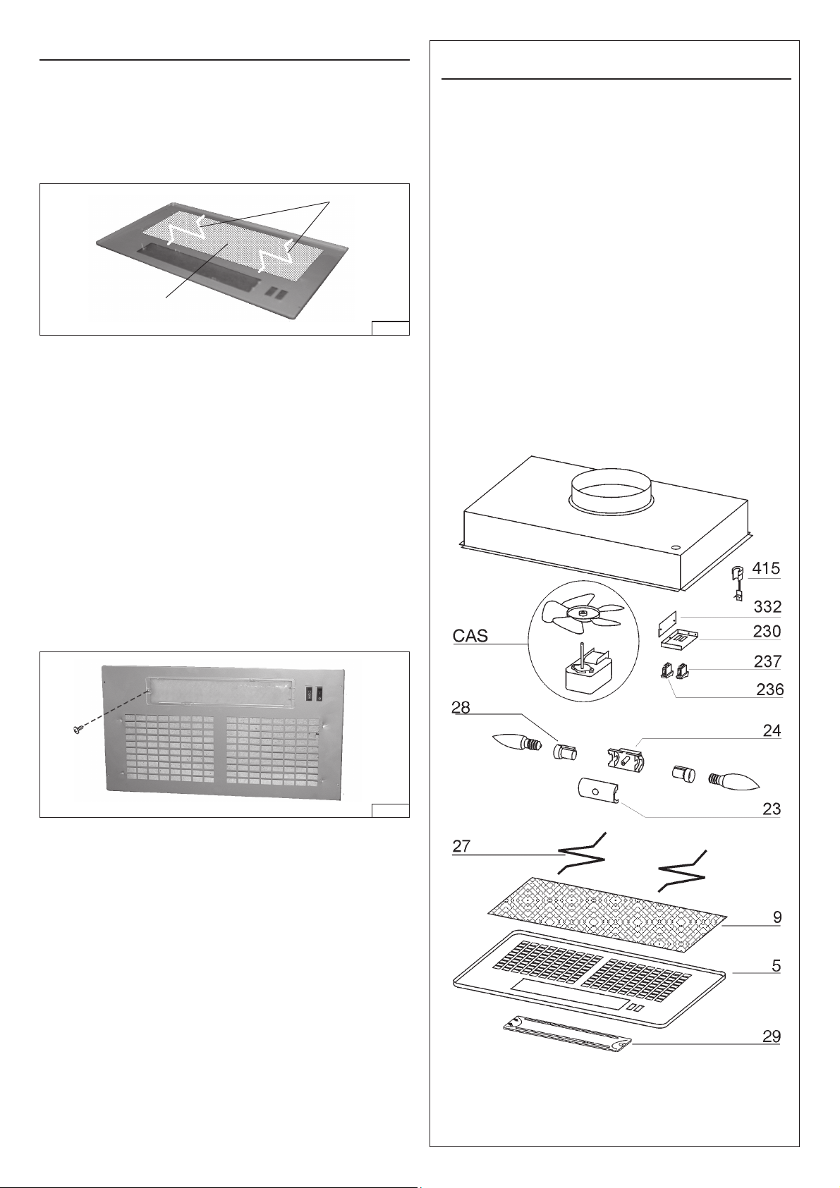
SERVICE PARTS
KEY NO. PART NO. DESCRIPTION
5 B03118152 Grid (White)
5 B03127681 Grid (Silver)
9 B08087922 Grease Filter
23 B03295095 Upper Lampholder
24 B03295094 Lower Lampholder
27 B02011270 Metal Wire
28 B02300280 Lampholder
29 B03294794 Light Fitting
230 BE3348475 Controls Closing
236 B02300822 Blower Switch (White)
236 B02300826 Blower Switch (Black)
237 B02300823 Light Switch (White)
237 B02300827 Light Switch (Black)
332 BE3248476 Cover Controls
415 B03202454 Strain Relief Bushing
CAS R730090 Blower Assembly
- B06108604 Socket Assembly
(Includes key No.24, 23, 28)
- - “40 Watt Max.Candelabra
Bulbs not included”
- B08999040 Non-Ducted Filter Kit
(purchased separately)
GREASE
FILTER
METAL WIRES
FIG. 7
FIG. 8
 Loading...