


Broan Erv200hc, Erv100hc, Hrv100h, Hrv200h, Gsfh1k Installation Guide
...
Installer Manual
VENTILATION SYSTEMS
VB0038
Canadian Model Numbers
1001 ERV
1001 HRV
U.S. Model Numbers
HRV100H
HRV200H
2001 ERV
2001 HRV
ERV100HC
ERV200HC
03119-03/09/09

Table of Contents
1.0 SERVICE..............................................................................................4
1.1 3-D Drawing ................................................................................4
1.2 Parts Ordering Chart....................................................................5
1.3 Technical Suppor t ........................................................................5
2.0 SIZING ................................................................................................6
3.0 UNIT TYPE & DEFROST SETTING VS GEOGRAPHICAL LOCATION ..7
4.0 TECHNICAL DATA ................................................................................8
4.1 Air Distribution (Normal Operation)..............................................8
4.2 Air Distribution (Defrost Mode) ....................................................8
4.3 Performance Charts................................................................9-12
4.4 Dimensions ................................................................................13
4.5 Controls and Furnace Link Option ............................................13
4.6 Specifications ............................................................................13
5.0 TYPICAL INSTALLATIONS ..................................................................14
5.1 Fully Ducted System..................................................................14
5.2 Exhaust Ducted System
5.3 Simplified
(Volume Ventilation)
(Source Point Ventilation)
..................................................14
..................14
6.0 INSTALLATION....................................................................................15
6.1 Adsjusting the Damper Rod (for ERVs installed in warm regions)..........15
6.2 Locating and Mounting the Unit ................................................15
6.3 Planning of the Ductwork ..........................................................16
6.4 Calculating the Duct Size ..........................................................16
6.4.1 Example Calculation........................................................16
6.4.2 Example of a Design for a Fully Ducted System ............17
6.5 Installing the Ductwork and Registers ......................................17
6.5.1 Fully Ducted System........................................................17
6.5.2 Exhaust Ducted System (Source Point Ventilation) ........18
6.5.3 Simplified Installation (Volume Ventilation)......................19
6.6 Connecting Duct to the Unit ......................................................20
6.7 Installing the Exterior Hoods......................................................21
6.8 Connecting the Drain ................................................................21
7.0 CONTROL DEVICES..........................................................................22
7.1 Main Controls ............................................................................22
7.2 Optional Control ........................................................................23
7.3 Other Features ..........................................................................23
7.4 Main and Optional Controls Available for your Unit ..................23
7.5 Special Cold Weather TBI Mode for ERVs ................................23
2

Table of Contents (cont’d)
!
8.0 INSTALLATION OF THE CONTROLS ..................................................24
8.1 Dimensions and Specifications ................................................24
8.2 Installation of the Main Control ..........................................24-25
8.3 Electrical Connection to Optional Controls ..............................26
8.4 Electrical Connection to the Furnace ......................................26
9.0 WIRING DIAGRAMS ....................................................................27-28
10.0 AIR F
LOW B
ALANCING................................................................29-30
11.0 OVERALL VERIFICATION ..................................................................31
11.1 Main Controls ..........................................................................31
11.2 Optional Control ......................................................................32
12.0 MAINTENANCE / INSTRUCTIONS FOR USER....................................33
13.0 TROUBLESHOOTING ....................................................................34-35
14.0 REFERENCES ....................................................................................36
About this Manual
This manual uses the following symbols to emphasize particular information:
WARNING
Identifies an instruction which, if not followed, might cause serious personal injuries including
possibility of death.
CAUTION
Denotes an instruction which, if not followed, may severely damage the unit and/or
its components.
NOTE: Indicates supplementary information needed to fully complete an instruction.
3

1.0 Service
1.1 3-D DRAWING
23
24
25
26
23
DAMPER ASSEMBLY (REAR VIEW)
3
22
21
20
10
18
19
16
15
12
11
13
17
14
9
6
1
2
3
4
5
7
8
VL0016
4

1.0 Service (cont’d)
1.2 PARTS ORDERING CHART
No Description
1 Double collar port #2 00866 00866 00866 00866 00866 00866 00866 00866
2 Wing nut #10-32 00874 00874 00874 00874 00874 00874 00874 00874
3 Balancing double collar port 02256 02256 02256 02256 02256 02256 02256 02256
4 Inlet ring 12913 12913 12913 12913 12913 12913 12913 12913
5 Top wheel 14307 03093 14308 03093 14307 03093 14308 03093
6 Electronic board V99 13507 13507 13507 13507 13508 13507 13508 13507
7 Motor assembly 13504 13555 13556 13506 13504 13555 13505 13506
8 Bottom wheel 02015 02015 03093 03093 02015 02015 03093 03093
9 Square balancing damper 12645 12645 12645 12645 12645 12645 12645 12645
10 Door latches (latch) 00886 00886 00886 00886 00886 00886 00886 00886
11 Drain connector 02418 02418 02418 02418 02418 02418 02418 02418
12 Drain gasket 0,625”D 02419 02419 02419 02419 02419 02419 02419 02419
13 Washer 5/8” ID x 1”OD 03117 03117 03117 03117 03117 03117 03117 03117
14 Nut 5/8-18 02420 02420 02420 02420 02420 02420 02420 02420
15 Recovery core 03132 03136 03133 03137 03134 03136 03135 03137
16 Door assembly 12644 12644 12644 12644 12648 12648 12648 12648
17 Door latches (keeper) 00887 00887 00887 00887 00887 00887 00887 00887
18 Hinge assembly 00672 00672 00672 00672 00672 00672 00672 00672
19 Filter 03096 03096 03097 03097 03096 03096 03097 03097
20 Switch E69 10A 01825 01825 01825 01825 01825 01825 01825 01825
21 Damper assembly #2 12643 12643 12649 12649 12643 12643 12649 12649
22 Plastic balancing damper 02253 02253 02253 02253 02253 02253 02253 02253
23 Damper rod 12620 12620 12620 12620 12620 12620 12620 12620
24 Double collar port #5 02021 02021 02021 02021 02021 02021 02021 02021
25 Damper #1 12459 12459 12459 12459 12459 12459 12459 12459
26 Damper actuator assembly 03124 03124 03124 03124 03124 03124 03124 03124
1001 1001 2001 2001 HRV ERV HRV ERV
HRV ERV HRV ERV 100H 100HC 200H 200HC
Please take note that parts not listed are not available;those parts require assembly knowledge that only
manufacturer can guarantee.
TO ORDER PARTS: Contact your local distributor
1.3 Technical Support (for assistance)
For assistance, call on week days, 8:30 AM to 5:00 PM (Eastern Standard Time).
Technical Support Department
Canada: tel: 1-888-908-2633 (for distributors only)
U.S.A.: tel: 1-800-637-1453
NOTE: Do not call these numbers for ordering parts.
5
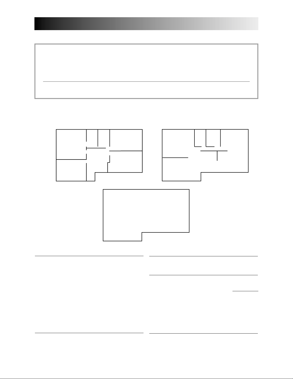
2.0 Sizing
These are the two most common methods used to evaluate the ventilation needs of a house:
CSA F326 and Canadian Building Code:
• High speed: 10 cfm per room
20 cfm for the master bedroom and the basement
• Low speed: 40-60% of high speed
ASHRAE Standard 62-2001:
• 0.35 air change per hour
Refer to ventilation code of your area to determine which method to use.
Example:
Second floor
Master
Bedroom
Bedroom #1
Bathroom
#1
Bathroom
#2
Bedroom
#2
Bedroom
#3
1320 ft
2
Basement
Basement
VH0021A
CSA F326
Kitchen (10 cfm)
Dining room (10
Living room (10
Family room (10
Master bedroom (20
Bedroom #1 (10
Bedroom #2 (10
Bedroom #3 (10
Bathroom #1 (10
Bathroom #2 (10
Bathroom #3 (10
Laundry room (10
Basement (20 cfm)
cfm)
cfm)
cfm)
cfm)
cfm)
cfm)
cfm)
cfm)
cfm)
cfm)
cfm)
Main floor
Laundry
room
Bathroom
Living room
Family room
2
1320 ft
#3
ASHRAE Standard 62-2001
Volume of basement 10560 ft
Volume of main floor 10560 ft
Volume of second floor 10560 ft
Total volume 31680 ft
Kitchen
Dining room
2
1320 ft
11090 ft3/h
÷ 60 (min/h)
x .35/h
3
3
3
3
Total 150
(high speed)
cfm
Total 185 cfm
(high speed)
6

3.0
Unit Type and Defrost Setting vs Geographical Location
ST JOHN'S
GOOSE BAY
CHARLOTTETOWN
BATHURST
QUEBEC
HALIFAX
ST-JOHN
BOSTON
SYMPTOM SOLUTION
(condensation)
SEPT-ILES
LABRADOR CITY
GASPÉ
MATANE
YELLOWKNIFE
HAY RIVER
FORT SMITH
ZONE A
FORT MCMURRAY
GRANDE PRAIRIE
PRINCE ALBERT
SASKATOON
EDMONTON
JASPER
CHIBOUGAMAU
WINNIPEG
REGINA
CALGARY
PENTICTON
KAMLOOPS
CHICOUTIMI
VAL-DOR
TIMMINS
ZONE B
HELENA
LETHBRIDGE
MONTRÉAL
OTTAWA
NORTH BAY
TORONTO
SUDBURY
SAULT STE MARIE
ST. PAUL
BISMARCK
HARTFORD
DETROIT
MADISON
DES MOINES
ZONE C
SALT LAKE CITY
BOISE
WASHINGTON
HARRISBURG
COLUMBUS
INDIANAPOLIS
SPRINGFIELD
TOPEKA
DENVER
RENO
RALEIGH
COLUMBIA
NASHVILLE
OKLAHOMA CITY
SANTA FE
ATLANTA
ZONE D
PHOENIX
BATON ROUGE
AUSTIN
Excess moisture problem ERV
Important excess moisture problem HRV
Indoor air quality problem ERV
and / or
ZONE C SELECTION CHART
and / or
see ZONE C SELECTION CHART beside
WHITEHORSE
ANCHORAGE
JUNEAU
Prince Rupert
VICTORIA
OLYMPIA
SALEM
HRV MODELS: 1001 HRV, 2001 HRV, HRV 100H, HRV 200H.•ERV MODELS: 1001 ERV, 2001 ERV, ERV 100HC, ERV 200HC.
problems)
SACRAMENTO
VN0002
•
ZONE C (HRV or ERV according to your client’s particular
(HRVs only)
Set Extended Defrost according to section 8.2, point 10.
•
ZONE A
ZONE D ERVs recommended)
(HRVs only)
MODELS: 1001 HRV, 2001 HRV, HRV 100H, HRV 200H.
•
ZONE B
• ERV MODELS: 1001 ERV, 2001 ERV, ERV 100H, ERV 200H.
• ERVs: Set Defrost mode #1 according to section 6.1.
Extended Defrost setting not required (factory defrost
strategy pre-set).
MODELS: 1001 HRV, 2001 HRV, HRV 100H, HRV 200H
•
•
7

4.0 Technical Data
4.1 AIR DISTRIBUTION (NORMAL OPERATION)
Applicable to all model numbers.
STALE AIR
TO OUTSIDE
FRESH AIR
TO BUILDING
VF0013
4.2 A
IR DISTRIBUTION (DEFROST MODE)
Defrost Mode 1
Applicable to model numbers:
• 1001 HRV
• 2001 HRV
• HRV100H
• HRV200H
FRESH AIR
TO BUILDING
VF0020
FRESH AIR
FROM
OUTSIDE
STALE AIR
FROM
BUILDING
STALE AIR
FROM
BUILDING
Defrost Mode 2
Applicable to model numbers:
• 1001 ERV
• 2001 ERV
• ERV100HC
• ERV200HC
Model numbers ERV100HC
and ERV200HC should be
set to defrost mode 1 when
installed in warm regions
(Zone D, as defined in
Section 3.0). Refer to
Section 6.1 for setting
instructions.
For defrost cycles tables, refer to Section 9.0, Wiring Diagrams.
STALE AIR
TO OUTSIDE
FRESH AIR TO
BUILDING
VF0012
STALE AIR
FROM
BUILDING
8

4.0 Technical Data (cont’d)
225
175
200
150
125
100
75
50
25
0
05025 100 12575
150
VG0041
225
175
200
150
125
100
75
50
25
0
05025 100 12575
150
VG0042
4.3 PERFORMANCE CHARTS
MODEL NUMBER: 1001 ERV
Electrical requirements: 120 volts, 1.3 Amps
Exhaust Air Transfer Ratio: 0.06
VENTILATION PERFORMANCE
External Static Net Supply Gross AirFlow
Pressure Air Flow Supply Exhaust
Pa in. w.g. L/s cfm L/s cfm L/s cfm
25 0.1 81 173 87 184 93 197
50 0.2 78 165 83 175 86 182
75 0.3 72 152 76 162 80 169
100 0.4 67 142 71 151 77 163
125 0.5 55 117 59 124 67 143
150 0.6 46 98 49 104 56 118
175 0.7 36 77 39 82 41 87
200 0.8 30 63 32 67 24 51
Note: Unit operating at maximum speed.
ENERGY PERFORMANCE
Supply Net Average Sensible Recovery Apparent Sensible Latent Recovery
Temperature Airflow Power Efficiency Effectiveness Moisture Transfer
°C °F L/s cfm Watts % %
HEATING
0 32 29 60 56 71 79 0.53
0 32 47 100 80 64 73 0.41
0 32 65 137 126 60 68 0.36
-15 5 31 65 64 56 81 0.41
COOLING
35 95 28 59 52 45
MODEL NUMBER: 2001 ERV
Electrical requirements: 120 volts, 1.9 Amps
Exhaust Air Transfer Ratio: 0.06
(250 Pascals = 1” of water)
External Static Pressure - Pascals
Supply
(l/s)
Exhaust
(l/s)
Gross Airflow - L/s (0.47 L/s = 1 cfm)
Total Recovery Efficiency
VENTILATION PERFORMANCE
External Static Net Supply Gross Air Flow
Pressure Air Flow Supply Exhaust
Pa in. w.g. L/s cfm L/s cfm L/s cfm
25 0.1 109 231 116 245 128 271
50 0.2 107 228 114 241 123 260
75 0.3 101 214 107 227 118 249
100 0.4 95 201 101 213 110 233
125 0.5 86 182 91 193 103 217
150 0.6 79 167 83 177 92 195
175 0.7 62 132 66 140 81 172
200 0.8 40 85 43 90 55 116
Note: Unit operating at maximum speed.
ENERGY PERFORMANCE
HEATING
COOLING
Supply
(l/s)
Exhaust
(l/s)
(250 Pascals = 1” of water)
External Static Pressure - Pascals
Gross Airflow - L/s (0.47 L/s = 1 cfm)
Supply Net Average Sensible Recovery Apparent Sensible Latent Recovery
Temperature Airflow Power Efficiency Effectiveness Moisture Transfer
°C °F L/s cfm Watts % %
0 32 52 110 93 69 76 0.45
0 32 74 157 130 64 71 0.38
0 32 96 203 193 60 68 0.30
-15 5 52 110 122 55 76 0.26
Total Recovery Efficiency
35 95 50 106 89 41
9

4.0 Technical Data (cont’d)
225
175
200
150
125
100
75
50
25
0
05025 100 12575
150
VG0039
4.3 PERFORMANCE CHARTS (CONT’D)
MODEL NUMBER: 1001 HRV
Electrical requirements: 120 volts, 1.3 Amps
Exhaust Air Transfer Ratio: 0.05
VENTILATION PERFORMANCE
External Static Net Supply Gross AirFlow
Pressure Air Flow Supply Exhaust
Pa in. w.g. L/s cfm L/s cfm L/s cfm
25 0.1 84 177 88 186 90 190
50 0.2 80 169 84 178 86 182
75 0.3 77 163 81 171 81 171
100 0.4 69 146 72 153 76 161
125 0.5 61 130 65 137 66 139
150 0.6 46 98 49 103 52 110
175 0.7 38 81 40 85 31 67
Note: Unit operating at maximum speed.
(250 Pascals = 1” of water)
External Static Pressure - Pascals
Supply
(l/s)
Exhaust
(l/s)
ENERGY PERFORMANCE
Gross Airflow - L/s (0.47 L/s = 1 cfm)
Supply Net Average Sensible Recovery Apparent Sensible Latent Recovery
Temperature Airflow Power Efficiency Effectiveness Moisture Transfer
°C °F L/s cfm Watts % %
HEATING
0 32 30 64 54 75 83 -0.03
0 32 46 97 78 67 74 0.01
0 32 65 138 124 64 72 -0.02
-25 -13 26 55 62 67 89 0.05
COOLING
35 95 Not tested
Total Recovery Efficiency
MODEL NUMBER: 2001 HRV
Electrical requirements: 120 volts, 1.9 Amps
Exhaust Air Transfer Ratio: 0.042
VENTILATION PERFORMANCE
External Static Net Supply Gross Air Flow
Pressure Air Flow Supply Exhaust
Pa in. w.g. L/s cfm L/s cfm L/s cfm
50 0.2 120 253 124 264 126 268
75 0.3 118 250 123 262 119 251
100 0.4 111 235 116 245 114 241
125 0.5 102 216 106 224 107 226
150 0.6 87 185 91 193 96 204
175 0.7 75 160 78 167 81 172
200 0.8 57 120 59 124 57 121
Note: Unit operating at maximum speed.
ENERGY PERFORMANCE
Supply Net Average Sensible Recovery Apparent Sensible Latent Recovery
Temperature Airflow Power Efficiency Effectiveness Moisture Transfer
°C °F L/s cfm Watts % %
HEATING
COOLING
0 32 51 109 92 70 77 -0.01
0 32 73 155 128 65 72 -0.02
0 32 102 215 191 62 70 -0.01
-25 -13 52 110 104 60 94 0.05
35 95 Not tested
External Static Pressure - Pascals
VG0040
225
200
175
150
125
100
75
(250 Pascals = 1” of water)
50
25
0
05025 100 12575
Gross Airflow - L/s (0.47 L/s = 1 cfm)
Total Recovery Efficiency
Supply
(l/s)
Exhaust
(l/s)
150
10

4.0 Technical Data (cont’d)
225
175
200
150
125
100
75
50
25
0
05025 100 12575
150
VG0043
225
175
200
150
125
100
75
50
25
0
05025 100 12575
150
VG0044
4.3 PERFORMANCE CHARTS (CONT’D)
MODEL NUMBER: HRV100H
Electrical requirements: 120 volts, 1.3 Amps
Exhaust Air Transfer Ratio: 0.05
VENTILATION PERFORMANCE
External Static Net Supply Gross AirFlow
Pressure Air Flow Supply Exhaust
Pa in. w.g. L/s cfm L/s cfm L/s cfm
25 0.1 78 164 81 172 83 176
50 0.2 74 156 78 165 80 168
75 0.3 71 151 75 158 75 158
100 0.4 64 135 67 142 70 149
125 0.5 56 120 60 127 61 129
150 0.6 43 91 45 95 48 102
175 0.7 35 75 37 79 29 62
Note: Unit operating at maximum speed.
(250 Pascals = 1” of water)
External Static Pressure - Pascals
Supply
(l/s)
Exhaust
(l/s)
ENERGY PERFORMANCE
Supply Net Average Sensible Recovery Apparent Sensible Latent Recovery
Temperature Airflow Power Efficiency Effectiveness Moisture Transfer
°C °F L/s cfm Watts % %
HEATING
0 32 30 64 54 72 80 -0.03
0 32 46 97 78 65 72 0.01
0 32 65 138 124 62 70 -0.02
-25 -13 26 55 62 65 87 0.05
COOLING
35 95 Not tested
MODEL NUMBER: HRV200H
Electrical requirements: 120 volts, 1.9 Amps
Exhaust Air Transfer Ratio: 0.04
VENTILATION PERFORMANCE
External Static Net Supply Gross Air Flow
Pressure Air Flow Supply Exhaust
Pa in. w.g. L/s cfm L/s cfm L/s cfm
50 0.2 107 226 111 236 113 240
75 0.3 106 224 110 234 107 225
100 0.4 99 210 104 219 102 216
125 0.5 91 193 95 200 96 202
150 0.6 78 166 81 173 86 183
175 0.7 67 143 70 149 72 154
200 0.8 51 107 53 111 51 108
Note: Unit operating at maximum speed.
(250 Pascals = 1” of water)
External Static Pressure - Pascals
Gross Airflow - L/s (0.47 L/s = 1 cfm)
Total Recovery Efficiency
Supply
(l/s)
Exhaust
(l/s)
ENERGY PERFORMANCE
HEATING
COOLING
Gross Airflow - L/s (0.47 L/s = 1 cfm)
Supply Net Average Sensible Recovery Apparent Sensible Latent Recovery
Temperature Airflow Power Efficiency Effectiveness Moisture Transfer
°C °F L/s cfm Watts % %
0 32 51 109 92 69 76 -0.01
0 32 73 155 128 65 72 -0.02
0 32 102 215 191 62 70 -0.01
-25 -13 52 110 104 60 94 0.05
Total Recovery Efficiency
35 95 Not tested
11
 Loading...