

USER GUIDE FOR
ERV120T, ERV120S, HRV120T, HRV120S,
ERV110T AND ERV110S UNITS
HRV and ERV
with top ports
ERV120T*
HRV120T*
and ERV110T
VB0238
HRV and ERV
with side ports
ERV120S*
HRV120S*
and ERV110S
VB0237
PLEASE READ AND SAVE THESE INSTRUCTIONS
www.broan.com
*These products earned the
ENERGY STAR® by meeting strict
energy efficiency guidelines set by
Natural Resources Canada and the
US EPA. They meet ENERGY STAR
requirements only when used in
Canada.
22642 rev. 01
Congratulations!
You have made an excellent choice! The operating principle of your Heat Recovery Ventilator
or your Energy Recovery Ventilator will give you personal comfort you have never known
before.
We have prepared this User Guide especially for you. Please read it carefully to ensure you
obtain full benefit from your unit. Over the coming months, you will increasingly appreciate the
feeling of living in a more comfortable home.
Please take note that this manual uses the following symbols to emphasize
particular information:
WARNING
!
Identifies an instruction which, if not followed, might cause serious personal injuries
including possibility of death.
CAUTION
Identifies an instruction which, if not followed, may severely damage the unit and/
or its components.
NOTE: Indicates supplementary information needed to fully complete an instruction.
We welcome any suggestions you may have concerning this guide and the unit, and we
would appreciate hearing your comments on ways to better serve you.
Please forward all correspondence to us at the address indicated on the product registration
card included with this guide.
CAUTION
Make sure at all times that the outdoor intake and exhaust hoods are free from any
snow during the winter season. It is important to check your unit during a big snow
storm, so it doesn’t draw in any snow. If this is the case, please operate the unit in
recirculation mode (if available), or turn it OFF for a few hours.
Do not use your unit during construction or renovation of your house or when
sanding drywall. This type of dust may damage your system.
Since the electronic control system of the unit is incorporated with a microprocessor,
it may not operate correctly because of external noise or very short power failure.
If this happens, unplug the unit and wait approximately 10 seconds. Then, plug the
unit in again.
CAUTION
When leaving the house for a long period of time (more than two weeks), a
responsible person should regularly check if the unit operates adequately.
If the ductwork runs through an unconditioned space (e.g.: attic), the unit must
operate continuously except when performing maintenance and/or repair. Also,
the ambient temperature of the house should never drop below 65°F. At least once
a year, the unit mechanical and electronic parts should be inspected by qualified
service personnel.
REPLACEMENT PARTS AND REPAIR
In order to ensure your ventilation unit remains in good working condition, you must
use Broan-NuTone LLC genuine replacement parts only. The Broan-NuTone LLC
genuine replacement parts are specially designed for each unit and are manufactured
to comply with all the applicable certification standards and maintain a high standard of
safety. Any third party replacement part used may cause serious damage and drastically
reduce the performance level of your unit, which will result in premature failing. Also,
Broan-NuTone LLC recommends to contact a Broan-NuTone LLC certified service depot
for all replacement parts and repairs.
2

TABLE OF CONTENTS
1. DEFROSTING MODE . . . . . . . . . . . . . . . . . . . . . . . . 3
ONTROLS. . . . . . . . . . . . . . . . . . . . . . . . . . . 4-5
2. C
2.1 INTEGRATED CONTROL . . . . . . . . . . . . . . . . . . . . . . . . 4
2.2 BOOT SEQUENCE . . . . . . . . . . . . . . . . . . . . . . . . . . 5
2.3 OPTIONAL MAIN AND AUXILIARY CONTROLS . . . . . . . . . . . . . . . 5
3. MAINTENANCE . . . . . . . . . . . . . . . . . . . . . . . . . 5-7
3.1 QUARTERLY MAINTENANCE . . . . . . . . . . . . . . . . . . . . . . . 6
3.2 ANNUAL MAINTENANCE . . . . . . . . . . . . . . . . . . . . . . . . 7
4. TROUBLESHOOTING . . . . . . . . . . . . . . . . . . . . . . . . 8
1. DEFROSTING MODE
When the outdoor temperature is below 23°F, heat (or energy) recovery creates frost in
the core.
To maintain its proper operation, the unit is programmed to defrost its core. The defrost
frequency varies according to the outdoor temperature.
During the defrost cycle, the dampers close and the unit turns on high speed.
After defrosting, the unit returns to the operating mode selected by the user.
3
2. CONTROLS
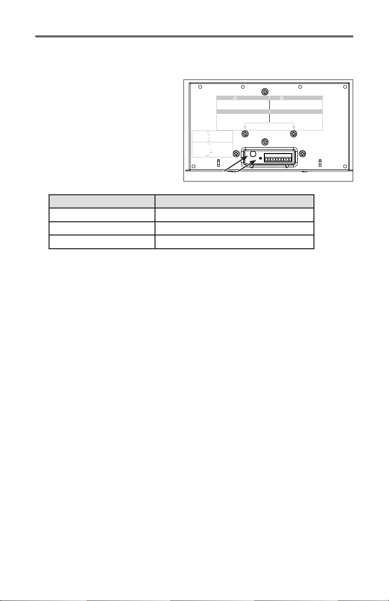
2.1 INTEGRATED CONTROL
All units are equipped with an
integrated control, located under
the unit, in front of the electrical
compartment. Use the push button (1)
to control the unit. The LED (2) will
then shows on which mode the unit is
in. Refer to table below.
No li ght OFF or remote controled
Amber light LOW speed
Green ligh HIGH speed
Blinking light See User Manual
Sans lumière Arrêté ou contrôlé
par contrôle mural
Lumière ambre Basse vitesse
Lumière verte Haute vitesse
Clignotant Voir guide d’utilisation
VD0182
WARNING
Risk of electric shock. Before performing
any maintenance or servicing, always
disconnect the unit from its power source.
CAUTION
Unscrew both screws to open the electrical
compartment. To completely remove, detach
from its retention wire inside.
12
AVERTISSEMENT
Danger d’électrocution. Débranchez
toujours l’appareil avant d’entreprendre
des travaux d’entretien ou de réparation.
ATTENTION
Dévisser les deux vis pour ouvrir le compartiment
électrique. Pour retirer complètement, le
détacher de son fil de rétention intérieur.
LED COLOR RESULTS
AMBER UNIT IS ON LOW SPEED
GREEN UNIT IS ON HIGH SPEED
NO LIGHT UNIT IS OFF OR CONTROLLED BY A MAIN CONTROL
If a problem occurs during the unit operation, its integrated control LED (2) will blink.
The color of the blinking light depends on the type of error detected. Refer to Section 4
TROUBLESHOOTING on last page for further details.
NOTE: When using an optional main wall control, the integrated control must
be turned off.
4
2. CONTROLS (CONT’D)
2.2 BOOT SEQUENCE
The unit boot sequence is similar to a personal computer boot sequence. Each time
the unit is plugged after being unplugged, or after a power failure, the unit will perform
a 30-second booting sequence before starting to operate. During the booting sequence,
the integrated control LED will light GREEN or AMBER for 5 seconds, and then will shut
off for 2 seconds. After that, the LED will light RED for the rest of the booting sequence.
During this RED light phase, the unit is checking and resetting the motorized damper
position. Once the motorized damper position completely set, the RED light turns off and
the booting sequence is done.
NOTE: No command will be taken until the unit is fully booted.
2.3 OPTIONAL MAIN AND AUXILIARY CONTROLS
For more convenience, these units can also be controlled using an optional main control.
Only one main control can be connected per unit.
NOTES: 1. The integrated control must be turned OFF to use an optional main control.
2. If an optional auxiliary control is used, its activation will override the main
control operation.
For more information about your unit controls, refer to the Main and auxiliary wall controls
user guide (included with your unit and also available at www.broan,com).
3. MAINTENANCE
!
WARNING
Risk of electric shock. Before performing any maintenance or servicing, always
disconnect the unit from its power source. When cleaning the unit, it is recommended
to wear safety glasses and gloves.
Since this guide covers both HRV and ERV units, top and side ports, the illustrations shown
in the maintenance procedures are typical. The following procedures applies for both HRV
and ERV units. Refer to pictures below to identify the inner parts of your unit.
VB0078
HRV core Foam filter brackets
Core retainers Core foam filters
VB0077
ERV core Foam filter brackets
Core retainers Core foam filters
5

3. MAINTENANCE (CONT’D)
3.1 QUARTERLY MAINTENANCE
Unplug the unit.
!
WARNING
Be careful while opening the door; water or small debris could fall out. For
HRV units, always wait one minute after disconnecting the unit before opening
the door in order to allow water to drain out from the unit.
Unlatch the door and open it. Clean the inner side
of the door with a damp cloth, then wipe with a
dry one. Disengage the door from its hinge by sliding
it from left to right and set aside.
VD0179
Lift both foam filter brackets in order to
remove the foam filters from the core.
VB0078
Wash the 2 core filters under hot water with mild soap. Rinse thoroughly and let dry
completely before reinstalling on the core.
Reinstall both foam filters and secure them to the core by pulling down the 2 foam
filter brackets. Reinstall the door.
Close the door and plug the unit.
NOTE: The unit will return to its previous setting after a 30-second delay for boot
sequence.
6

3. MAINTENANCE (CONT’D)
3.2 ANNUAL MAINTENANCE
Repeat steps and from the Quarterly Maintenance (Section 3.1). Then, proceed
as follows:
!
WARNING
Always hold the core when rotating the
two core retainers; failure to do so will
cause the core to fall out.
Lift both foam filter brackets and
remove the foam filters from the core.
While holding the core, rotate the 2 core
retainers and slide out the core from
the unit.
VD0177
Clean the inside walls of the unit with a clean damp cloth, then wipe with a clean dry one.
Wash the 2 core filters under hot water with mild soap. Rinse thoroughly and let dry
completely before reinstalling on the core.
Heat recovery core: Allow the core to soak for 3 hours in a solution of warm water
and mild soap (liquid soap). Rinse lightly, let dry and reinstall.
Energy recovery core: Remove the dust on the core using a vacuum cleaner and a soft
brush attachment.
CAUTION
Do not soak the energy recovery core in water. This core can easily be damaged
especially if it is soaked.
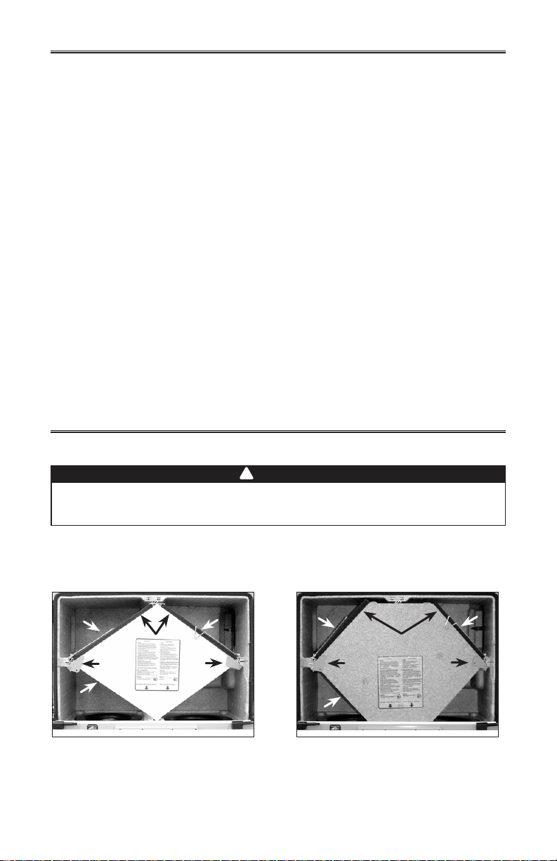
!
WARNING
Once the core reinstalled in the unit, always rotate both core retainers to their
initial position; failure to do so will cause the core to fall out.
Slide the core in the unit. Secure the
core by rotating both core retainers to
their initial position.
NOTE: Once the core reinstalled in the
unit, the arrows (circled in picture
below) on its sticker label must be
pointing towards the unit motors.
VD0078
VB0078
Reinstall both foam filters and secure them to the core by pulling down the 2 foam
filter brackets. Reinstall the door.
Close the door and plug the unit.
NOTE: The unit will return to its previous setting after a 30-second delay for boot
sequence.
Clean the exterior hood(s).
7

4. TROUBLESHOOTING
If the unit does not work properly, reset the unit by unplugging it for one minute and
then replug it. If it still not working properly, refer to table below.
PROBLEMS TRY THIS
1. Nothing works. • See if the unit is plugged in.
• See if the unit is receiving power from the
house circuit breaker or fuse.
2. Condensation on windows
(air too humid).
3. Inside air too dry. • Temporarily use a humidifier.
4. Air too cold at the air supply
grille.
5. The LED of the integrated control
is blinking RED.
6. The LED of the integrated control
is blinking GREEN.
7. The LED of the integrated control
is blinking AMBER.
8. The integrated control
push button does not work.
• Operate the unit on maximum speed ventilation
until the situation is corrected.
• Leave curtains half-open to allow air circulation.
• Store all firewood in a closed room with a
dehumidifier or in a well ventilated room, or store
the wood outdoors.
• Do not adjust the thermostat of your heating
system below 64°F.
• Operate the unit in recirculation mode (if available).
• Check if the exterior hood is not blocked.
• Operate the unit in low speed ventilation or in
intermittent or recirculation mode (if available).
• Install a duct heater.
a) The door is open and the unit is not unplugged.
Close the door and press once on the integrated
control push button to reset the unit.
b) There is a problem with the exhaust motor. The
unit is OFF. Contact your installer.
• There is a problem with the thermistor. The
unit is still working, but will defrost frequently.
Contact your installer.
• There is a problem with the motorized damper.
The unit is OFF. For a 12-hour period, the unit will
try to reset the damper at every 20 to 30 minutes.
After 12 hours, if the problem is not solved, the
unit stops trying to reset damper.
• Contact your installer.
• The 30-second boot sequence is not completed.
See Section 2.2 on page 5.
• If the booting sequence is completed and the
push-button still doesn’t work, contact your installer.
For wall controls problems, refer to the Troubleshooting section in the Main and auxiliary wall
controls user guide (included with the ventilation unit and also available at www.broan.com).
If the problem is still not solved, call your installer or the nearest approved Service Center.
Also, you can reach the Customer Service Department at the following phone number:
1-877-862-7626.
8

GUÍA DEL USUARIO PARA UNIDADES
ERV120T, ERV120S, HRV120T, HRV120S,
ERV110T Y ERV110S
HRV y ERV con
aberturas en la
parte superior
ERV120T*
HRV120T*
y ERV110T
VB0238
HRV y ERV
con aberturas
laterales
ERV120S*
HRV120S*
VB0237
y ERV110S
LEA Y CONSERVE ESTAS INSTRUCCIONES
www.broan.com
*Estos productos han sido distinguidos con el logotipo ENERGY STAR®
al cumplir las directrices de eficiencia energética establecidas por el
Ministerio de Recursos Naturales de Canadá y la Agencia Federal
de Protección Ambiental (EPA) de Estados Unidos. Los productos
cumplen las exigencias del programa ENERGY STAR únicamente
cuando se emplean en Canadá.
22642 rev. 01

¡Felicitaciones!
Ha tomado una excelente decisión. El principio de funcionamiento del ventilador para la
recuperación del calor y del ventilador para la recuperación de energía le brindará un confort
personal desconocido.
Este manual del usuario ha sido preparado especialmente para usted. Léalo atentamente
para sacar el máximo partido del aparato. En los próximos meses agradecerá cada vez más
la sensación de llegar a una casa más confortable.
Con el fin de hacer hincapié en determinada información, en este manual se emplean los
siguientes símbolos:
ADVERTENCIA
!
Se refiere a una instrucción que, de no seguirse, podría causar daños
corporales e incluso la muerte.
CUIDADO
Se refiere a una instrucción que, de no seguirse, podría dañar gravemente
el aparato o sus componentes.
NOTA: Indica una información complementaria que es necesaria para completar totalmente
una instrucción.
Con el fin de ofrecerle mejor servicio, no dude en enviarnos sus comentarios o sugerencias
en relación con esta guía o con el aparato. Para ello, comunique con nosotros en la dirección
que aparace en la tarjeta de registro que acompaña este producto.
CUIDADO
Compruebe siempre que la toma exterior y las bocas de aspiración estén libres de
nieve en invierno. Es importante verificar el aparato en caso de fuerte nevada para
que no quede hundido en la nieve. Si esto ocurriera, utilice el aparato en el modo de
recirculación (si disponible) o APÁGUELO durante unas horas.
No utilice el aparato cuando haya obras de construcción o renovación en su casa o
cuando se estén lijando paneles murales de yeso. Este tipo de polvo puede dañar
el sistema.
El aparato está equipado con un control electrónico con microprocesadores y
podría funcionar incorrectamente debido a la presencia de parásitos externos o de
cortes de corrientes muy cortos. Si esto sucede, desconecte el cable de alimentació,
espere unos 10 segundos y vuélvalo a conectar.
CUIDADO
Si no va a estar en la casa durante un largo periodo (más de dos semanas), un
responsable debería verificar regularmente que el aparato funciona debidamente. Si
las tuberías pasa a través de un espacio do acondicionado (p. ej., un altillo), el aparato
debería funcionar constantemente, menos cuando se repare o se limpie. Asimismo, la
temperatura ambiente de la casa nunca debería bajar de 65°F. El personal de servicio
autorizado inspeccione las piezas electrónicas y mecánicas del aparato una vez al
año como mínimo.
SUSTITUCIóN DE PIEZAS Y REPARACIóN
Para que la unidad se conserve en buen estado, debe usar repuestos genuinos de
Broan-NuTone LLC únicamente. Estas piezas se han diseñado especialmente para
cada unidad y se han fabricado conforme a las normas de certificación aplicables y un
elevado nivel de seguridad. El uso de repuestos de otros fabricantes podría causar daños
graves y reducir radicalmente el desempeño de la unidad, causando así fallas prematuras.
Broan-NuTone LLC también aconseja ponerse en contacto con un taller de reparación
homologado por Broan-NuTone LLC para todos los repuestos y reparaciones.
2

ÍNDICE
1. MODO DESHIELO . . . . . . . . . . . . . . . . . . . . . . . . . 3
ONTROLES . . . . . . . . . . . . . . . . . . . . . . . . . . 4-5
2. C
2.1 CONTROL INTEGRADO . . . . . . . . . . . . . . . . . . . . . . . . . 4
2.2 SECUENCIA DE PUESTA EN MARCHA . . . . . . . . . . . . . . . . . . . 5
2.3 CONTROLES PRINCIPALES Y AUXILIARES OPCIONALES . . . . . . . . . . . 5
3. MANTENIMIENTO . . . . . . . . . . . . . . . . . . . . . . . . 6-7
3.1 MANTENIMIENTO TRIMESTRAL . . . . . . . . . . . . . . . . . . . . . 6-7
3.2 MANTENIMIENTO ANUAL . . . . . . . . . . . . . . . . . . . . . . . . 7
4. SOLUCIÓN DE PROBLEMAS . . . . . . . . . . . . . . . . . . . . . 8
1. MODO DESHIELO
Cuando la temperatura exterior està por debajo de 23°F, la recuperación de calor o energía
crea hielo en el núcleo.
Para que el aparato siga funcionado bien, está programado para deshelar el núcleo de
recuperación. La frecuencia de deshielo varía en función de la temperatura exterior.
Durante el ciclo de deshielo el aparato pasa a la velocidad máxima y los dispositivos de cierre
se cierran. Una vez terminado el deshielo, el aparato vuelve al modo de funcionamiento que
haya seleccionado el usuario.
3

2. CONTROLES
2.1 CONTROL INTEGRADO
Todos los aparatos están
equipados con un control integrado
situado debajo del aparato, en el lado
empotrado del compartimento
eléctrico. Utilice el botón pulsador (1)
para controlar el aparato. El diodo (2)
le indicará el modo en el funciona el
aparato. Consulte la tabla siguiente
No li ght OFF or remote controled
Amber light LOW speed
Green ligh HIGH speed
Blinking light See User Manual
Sans lumière Arrêté ou contrôlé
par contrôle mural
Lumière ambre Basse vitesse
Lumière verte Haute vitesse
Clignotant Voir guide d’utilisation
WARNING
Risk of electric shock. Before performing
any maintenance or servicing, always
disconnect the unit from its power source.
CAUTION
Unscrew both screws to open the electrical
compartment. To completely remove, detach
from its retention wire inside.
AVERTISSEMENT
Danger d’électrocution. Débranchez
toujours l’appareil avant d’entreprendre
des travaux d’entretien ou de réparation.
ATTENTION
Dévisser les deux vis pour ouvrir le compartiment
électrique. Pour retirer complètement, le
détacher de son fil de rétention intérieur.
para saber cómo funciona el aparato.
VD0182
12
COLOR DEL DIODO EL APARATO
ÁMBAR
VERDE
NINGUNA LUZ
ESTÁ APAGADO O CONTROLADO PARA CONTROL PRINCIPAL
Si surge un problema cuando el aparato está funcionado, el diodo (2) del control integrado
parpadea. El color del intermitente depende del error detectado. Para mayor información
al respecto, consulte la sección 4 Solución de problemas en las últimas páginas.
NOTA: Al utilisar el control principal, el control integrado del aparato debe estar
apagado.
FUNCIONA A BAJA VELOCIDAD
FUNCIONA A ALTA VELOCIDAD
4

2. CONTROLES (CONTINUACIÓN)
2.2 SECUENCIA DE PUESTA EN MARCHA
La secuencia de puesta en marcha del aparato es similar a la de una computadora
personal. Cada vez que se enchufa el aparato después de haberlo desenchufado o tras
un corte de corriente, el aparato pasará por una secuencia de puesta en marcha de unos
30 segundos antes de empezar a funcionar.
Durante la secuencia, el diodo del control integrado se encenderá de color VERDE o
ÁMBAR durante 5 segundos, y luego se apagará durante 2 segundos. A continuación,
el diodo se encederá en ROJO durante el resto de la secuencia de puesta en marcha.
En esta última fase, el aparato verifica y configura la posición del dispositivo de cierre
motorizado. Una vez terminada esta operación, el diodo ROJO se apaga para indicar que
la secuencia de puesta en march ha terminado.
NOTA : El aparato no puedee responder a las instrucciones que se le dan mientras no
haya terminado la secuencia de puesta en marcha.
2.3 CONTROLES PRINCIPALES Y AUXILIARES OPCIONALES
Para mayor comodidad, estes aparatos también puede controlarse con un control
principal opcional. Solamente uno control principal puede estar conectado al aparato.
NOTAS: 1. Al utilizar el control integrado del aparato debe estar apagado para utilizar
2. Si se está utilizando un control auxiliar opcional (cuando está activado), el
Para mayor información sobre los controles de su unidad, consulte el Main and auxiliary
wall controls user guide (incluido con su aparato y disponible at www.broan.com).
un control principal.
mando de control auxiliar prevalece sobre el control principal opcional.
3. MANTENIMIENTO
!
ADVERTENCIA
Riesgo de choque eléctrico. Desenchufe el aparato antes de efectuar cualquier
reparación o actividad de mantenimiento. Para limpiar el aparato se aconseja llevar
lentes y guantes de seguridad.
Dado que esta guía cubre los aparatos HRV y ERV con aberturas laterales y en la parte
superior, las ilustraciones de esta sección son de carácter general. Las instrucciones
suguientes son válidas para los HRV y los ERV. Consulte estas fotos para identifiar las piezas
interiores del aparato.
VB0078
Núcleo HRV Soportes de los
filtros de espuma
Piezas de retención Filtros de espuma
VB0077
Núcleo ERV Soportes de los
filtros de espuma
Piezas de retención Filtros de espuma
5

3. MANTENIMIENTO (CONTINUACIÓN)
3.1 MANTENIMIENTO TRIMESTRAL
Desenchufe el aparato
!
ADVERTENCIA
Tenga cuidado al abrir la puerta del aparato; podrían caer residuos pequeños o
agua. En los aparatos HRV se aconseja esperar siempre un minuto después de
desenchufarlos antes de abrir la puerta para que el agua salga completamente
fuera del aparato.
Quite los pestillos para abrir la puerta. Limpie
la parte interna de la puerta con un trapo húmedo
y séquela con un trapo seco. Saque la puerta de
sus bisagras deslizándola de izquierda a derecha
y póngala de lado.
VD0179
Quite los dos soportes de los filtros de
espuma y retirer los dos filtros de
espuma del núcleo.
VB0078
Limpie los dos filtros de espuma de la unidad cental con agua caliente y un jabón
suave. Enjuáguelos y deje que sequen completamente antes de volver a instalarlos
en el núcleo.
Vuelva a instalar los dos filtros de espuma y sujételos a la unidad central con los
soportes de los filtros. Vuelva a instalar la puerta.
Cierre la puerta y enchufe el aparato.
NOTA: Tras la secuencia de puesta en marcha, que dura unos 30 segundos, el
aparato volverá a su configuración anterior.
6

3. MANTENIMIENTO (CONTINUACIÓN)
3.2 MANTENIMIENTO ANUAL
Repita los pasos y que se describen en el mantenimiento trimestral (sección 3.1),
y después proceder de la manera siguiente:
!
ADVERTENCIA
Sujete siempre la unidad central
al hacer pivotar sus dos piezas de
retención, de lo contrario, el núcleo
caerá fuera del aparato.
Quite los dos soportes de los filtros de
espuma y retirer los dos filtros de
espuma del núcleo. Sujete el núcleo y haga
pivotar sus dos piezas de retención y
saque el núcleo del aparato.
VD0177
Limpie las paredes interiores del aparato con un trapo limpio y húmedo y séquelas
con otro trapo limpio y seco.
Limpie los dos filtros de espuma del núcleo con agua caliente y un jabón suave.
Enjuáguelos y deje que sequen completamente antes de volver a instalarlos en el
núcleo.
Núcleo HRV: Remoje el núcleo durante 3 horas en una solución de agua tibia y jabón
liquido. Enjuague ligeramente, deje secar y reinstale
Núcleo ERV: Quite el polvo del núcleo con una aspiradora equipada con un cepillo suave.
CUIDADO
No remoje o sumerja el núcleo de recuperación de energía en agua. Este núcleo
puede ser fácilmente dañado, especialmente si es remojado
!
ADVERTENCIA
Una vez instalada la unidad central en el aparato, coloque las dos piezas de
retención en su posición inicial; de lo contrario, el núcleo caerá fuera del aparato.
Coloque el núcleo dentro del aparato.
Sujételo el núcleo haciendo pivotar
sus dos piezas de retención hasta su
posición inicial.
NOTA: Una vez instalado el núcleo en el
aparato, las flechas (circuladas
en la illustración de abajo), deben
indicar hacia los motores.
.
VB0078VD0178
Vuelva a instalar los dos filtros de espuma y sujételos a la unidad central con los
soportes de los filtros. Vuelva a instalar la puerta.
Cierre la puerta y enchufe el aparato.
NOTA: Tras la secuencia de puesta en marcha, que dura unos 30 segundos, el
aparato volverá a su configuración anterior.
Limpie la(s) boca(s) exterior(es)
7

4. SOLUCIóN DE PROBLEMAS
Si el aparato no funciona debidamente, desenchúfelo durante un minuto y vuélvalo
a enchufar para reiniciarlo. Si sigue sin funcionar debidamente, consulte la tabla de
abajo.
PROBLEMA DEBERÍA HACER ESTO
1. El aparato no
funciona.
2. Condensación
en las ventanas
(aire demasiado
húmedo).
3. Aire interior
demasiado seco.
4. Aire demasiado frío
en la rejilla de
alimentación de aire.
5. El diodo del control
integrado parpadea
en ROJO.
6. El diodo del control
integrado parpadea
en VERDE.
7. El diodo del control
integrado parpadea
en ÁMBAR.
8. El botón pulsador
del control integrado
no funciona.
Si tiene problemas con controles, refiera a la sección Solución de problemas en la guía Main and
auxiliary wall controls user guide (incluida con su aparato y disponible en www.broan.com).
Si lel problema sigue, llame a su instalador o al centro de sevicio homologado
más próximo. También puede telefonar al Servicio de Atención al Cliente en el
• Verifique si el aparato está enchufado.
• Verifique si el aparato recibe corriente del interruptor
automático o del fusible de la casa.
• Ponga el aparato en alta velocidad hasta que el problema
se corija.
• Deje las cortinas medio abiertas para permitir la circulación
de aire.
• Guarde toda la leña en un cuarto cerrado equipado con un
deshumidificador, en un cuarto bien ventilado o en el
exterior.
• No ajuste el termostato de su sistema de calefacción por
debajo de 64 °F
• Utilice temporalmente un deshumidificador.
• Ponga el aparato en el modo recirculación
(si disponible).
• Compruebe que las bocas exteriores no estén bloqueadas,
especialmente las del aire de salida al exterior.
• Ponga el aparato en baja velocidad, intermittente o en el
modo reciculación (si disponible).
• Instale un generador de aire caliente.
a) La puerta está abierta y el aparato no está desenchifado.
Cierre la puerta y presione una vez en el botón pulsador
del control.
b) El motor de extracción tiene dificultades. El aparato
está apagado. Comunique con su instalador.
• El problema se encuentra en el termistor. El aparato sigue
funcionando, pero deshielo con frecuencia. Póngase en
contacto con su instalador.
• Hay un problema con el registro motorizado. El aparato
está apagado. Durante 12 horas, el aparato tratará de reiniciar
el registro cada 20 a 30 minutos. Si, al terminar de las
12 horas, el problema no se ha resuelto, el aparato se
detendrá.
• Póngase en contacto con su instalador.
• La secuencia de puesta en marcha de 30 segundos no se
ha completado, véase la sección 2.2 en la página 5.
• Si la secuencia de puesta en marcha ha terminado, que el
botón pulsador del control ya no funciona, y que el
problema no se ha resuelto, Comunique con su instalador.
número : 1-877-862-7626
8
 Loading...