


Broan ERV90HCS, ERV90HC, HRV90H, HRV90HS User Manual

INSTALLATION INSTRUCTIONS
HRV90H AND ERV90HC
RESIDENTIAL USE ONLY
READ AND SAVE THESE INSTRUCTIONS
06010C rev. E
Model no.: HRV90HT
(HRV with ports on top)
Model no.: HRV90HS
(HRV with ports on sides)
Model no.: ERV90HCT
(ERV with ports on top)
Model no.: ERV90HCS
(ERV with ports on sides)
VB0082
VB0080 VB0079
VB0081
ABOUT THIS MANUAL
Because of the large amount of models covered by this publication, the illustrations are typical ones. Some details of your unit may be
slightly different than the ones shown.
Please take note that this manual uses the following symbols to emphasize particular information:
NOTE: Indicates supplementary information needed to fully complete an instruction.
We welcome any suggestions you may have concerning this manual and/or the unit, and we would appreciate hearing your comments
on ways to better serve you. Please contact us by phone at 1-800-558-1711.
WARNING
Identifies an instruction which, if not followed, might cause serious personal injuries including possibility of death.
!
CAUTION
Denotes an instruction which, if not followed, may severely damage the unit and/or its components.
- 2 -
!
TO REDUCE THE RISK OF FIRE, ELECTRIC SHOCK, OR INJURY TO PERSON(S) OBSERVE THE FOLLOWING:
1. Use this unit only in the manner intended by the manufacturer. If you have questions, contact the manufacturer at the address or
telephone number listed in the warranty.
2. Before servicing or cleaning the unit, disconnect power cord from electrical outlet.
3. This unit is not designed to provide combustion and/or dilution air for fuel-burning appliances.
4. When cutting or drilling into wall or ceiling, do not damage electrical wiring and other hidden utilities.
5. Do not use this unit with any solid-state speed control device other than main optional wall control VT4W, and no other optional
auxiliary wall controls than 60-minute crank timer and/or 20-minute lighted push button and/or Humidity Control.
6. This unit must be grounded. The power supply cord has a 3-prong grounding plug for your personal safety. It must be plugged into a
mating 3-prong grounding receptacle, grounded in accordance with the national electrical code and local codes and ordinances. Do
not remove the ground prong. Do not use an extension cord.
7. Do not install in a cooking area or connect directly to any appliances.
8. Do not use to exhaust hazardous or explosive materials and vapors.
CAUTION
1. To avoid prematurate clogged filters, turn OFF the unit during construction or renovation.
2. Please read specification label on product for further information and requirements.
3. Be sure to duct air outside – Do not intake / exhaust air into spaces within walls or ceiling or into attics, crawl spaces, or garage.
4. Intended for residential installation only in accordance with the requirements of NFPA 90B.
5. Do not run any air ducts directly above or closer than 2 ft (0.61 m) to any furnace or its supply plenum, boiler, or other heat producing
appliance. If a duct has to be connected to the furnace return plenum, it must be connected not closer than 9’10” (3 m) from this
plenum connection to the furnace.
6. The ductwork is intended to be installed in compliance with all local and national codes that are applicable.
WARNING
ABOUT THESE UNITS
LIMITATION
For residential (domestic) installation only. This unit must be installed in accordance with all national and local regulations, building codes
and safety codes.

1.0 TECHNICAL DATA . . . . . . . . . . . . . . . . . . . . . . . . . . . . . . . . . . . . . . . . . . . . . . . . . . . . . . . . . .4-6
1.1 AIR DISTRIBUTION (NORMAL OPERATION) . . . . . . . . . . . . . . . . . . . . . . . . . . . . . . . . . . . . . . . . . . . . . . . . . . . . .4
1.2 A
IR DISTRIBUTION (RECIRCULATION OR DEFROST MODE) . . . . . . . . . . . . . . . . . . . . . . . . . . . . . . . . . . . . . . . . . .4
1.3 S
PECIFICATIONS . . . . . . . . . . . . . . . . . . . . . . . . . . . . . . . . . . . . . . . . . . . . . . . . . . . . . . . . . . . . . . . . . . . . . . .4
1.4 P
ERFORMANCE CHARTS . . . . . . . . . . . . . . . . . . . . . . . . . . . . . . . . . . . . . . . . . . . . . . . . . . . . . . . . . . . . . . . . .5
1.5 D
IMENSIONS
. . . . . . . . . . . . . . . . . . . . . . . . . . . . . . . . . . . . . . . . . . . . . . . . . . . . . . . . . . . . . . . . . . . . . . . . .6
1.6 C
ONTROLS AND LINKAGE POSSIBILITY . . . . . . . . . . . . . . . . . . . . . . . . . . . . . . . . . . . . . . . . . . . . . . . . . . . . . . .6
2.0 TYPICAL INSTALLATIONS . . . . . . . . . . . . . . . . . . . . . . . . . . . . . . . . . . . . . . . . . . . . . . . . . . . . .7-8
2.1 FULLY
DUCTED SYSTEM . . . . . . . . . . . . . . . . . . . . . . . . . . . . . . . . . . . . . . . . . . . . . . . . . . . . . . . . . . . . . . . ..7
2.2 CENTRAL DRAW POINT . . . . . . . . . . . . . . . . . . . . . . . . . . . . . . . . . . . . . . . . . . . . . . . . . . . . . . . . . . . . . . . . . .7
2.3 S
IMPLIFIED INSTALLATION . . . . . . . . . . . . . . . . . . . . . . . . . . . . . . . . . . . . . . . . . . . . . . . . . . . . . . . . . . . . . . . . .7
2.4 INSTALLATION FOR ERV U
NITS ONLY . . . . . . . . . . . . . . . . . . . . . . . . . . . . . . . . . . . . . . . . . . . . . . . . . . . . . . . .8
3.0 INSTALLATION . . . . . . . . . . . . . . . . . . . . . . . . . . . . . . . . . . . . . . . . . . . . . . . . . . . . . . . . . . . .9-16
3.1 I
NSPECT THE C
ONTENT OF THE BOX . . . . . . . . . . . . . . . . . . . . . . . . . . . . . . . . . . . . . . . . . . . . . . . . . . . . . . . .9
3.2 L
OCATING THE UNIT . . . . . . . . . . . . . . . . . . . . . . . . . . . . . . . . . . . . . . . . . . . . . . . . . . . . . . . . . . . . . . . . . . . .9
3.3 U
NIT
PREPARATION . . . . . . . . . . . . . . . . . . . . . . . . . . . . . . . . . . . . . . . . . . . . . . . . . . . . . . . . . . . . . . . . . . . .9
3.4 H
OW TO HANG THE UNIT . . . . . . . . . . . . . . . . . . . . . . . . . . . . . . . . . . . . . . . . . . . . . . . . . . . . . . . . . . . . . . .10
3.5 PLANNING OF THE DUCTWORK . . . . . . . . . . . . . . . . . . . . . . . . . . . . . . . . . . . . . . . . . . . . . . . . . . . . . . . . . . .10
3.6 I
NSTALLING THE DUCTWORK AND REGISTERS . . . . . . . . . . . . . . . . . . . . . . . . . . . . . . . . . . . . . . . . . . . . . .10-12
3.7 CONNECTING THE DUCT TO THE UNIT . . . . . . . . . . . . . . . . . . . . . . . . . . . . . . . . . . . . . . . . . . . . . . . . . . . . . .13
3.8 I
NSTALLING THE
TANDEM® T
RANSITION KIT . . . . . . . . . . . . . . . . . . . . . . . . . . . . . . . . . . . . . . . . . . . . . . . .13-15
3.9 I
NSTALLING
2 EXTERIOR HOODS . . . . . . . . . . . . . . . . . . . . . . . . . . . . . . . . . . . . . . . . . . . . . . . . . . . . . . . . . .16
4.0 CONTROLS . . . . . . . . . . . . . . . . . . . . . . . . . . . . . . . . . . . . . . . . . . . . . . . . . . . . . . . . . . . .17-19
4.1 I
NTEGRATED C
ONTROL . . . . . . . . . . . . . . . . . . . . . . . . . . . . . . . . . . . . . . . . . . . . . . . . . . . . . . . . . . . . . . . . .17
4.2 E
LECTRICAL CONNECTION TO OPTIONAL WALL CONTROLS . . . . . . . . . . . . . . . . . . . . . . . . . . . . . . . . . . . . .17-18
4.3 VT4W O
PTIONAL MAIN WALL CONTROL OPERATION . . . . . . . . . . . . . . . . . . . . . . . . . . . . . . . . . . . . . . . . . . . .18
4.4 O
PTIONAL AUXILIARY WALL CONTROLS OPERATION . . . . . . . . . . . . . . . . . . . . . . . . . . . . . . . . . . . . . . . . . . . .19
5.0 E
LECTRICAL C
ONNECTION TO THE FURNACE
. . . . . . . . . . . . . . . . . . . . . . . . . . . . . . . . . . . . . . . .19
6.0 W
IRING DIAGRAM . . . . . . . . . . . . . . . . . . . . . . . . . . . . . . . . . . . . . . . . . . . . . . . . . . . . . . . . . .20
7.0 BALANCING THE UNIT . . . . . . . . . . . . . . . . . . . . . . . . . . . . . . . . . . . . . . . . . . . . . . . . . . . . . . . .22
8.0 CONNECTING THE DRAIN . . . . . . . . . . . . . . . . . . . . . . . . . . . . . . . . . . . . . . . . . . . . . . . . . . . . .21
9.0 M
AINTENANCE . . . . . . . . . . . . . . . . . . . . . . . . . . . . . . . . . . . . . . . . . . . . . . . . . . . . . . . . . .23-24
9.1 BIANNUAL MAINTENANCE . . . . . . . . . . . . . . . . . . . . . . . . . . . . . . . . . . . . . . . . . . . . . . . . . . . . . . . . . . . . .23-24
9.2 A
NNUAL MAINTENANCE . . . . . . . . . . . . . . . . . . . . . . . . . . . . . . . . . . . . . . . . . . . . . . . . . . . . . . . . . . . . . . . . .24
10.0 SERVICE PARTS . . . . . . . . . . . . . . . . . . . . . . . . . . . . . . . . . . . . . . . . . . . . . . . . . . . . . . . . . . . .25
11.0 T
ROUBLESHOOTING . . . . . . . . . . . . . . . . . . . . . . . . . . . . . . . . . . . . . . . . . . . . . . . . . . . . . . . . .26
TABLE OF CONTENTS
- 3 -
HRV ERV
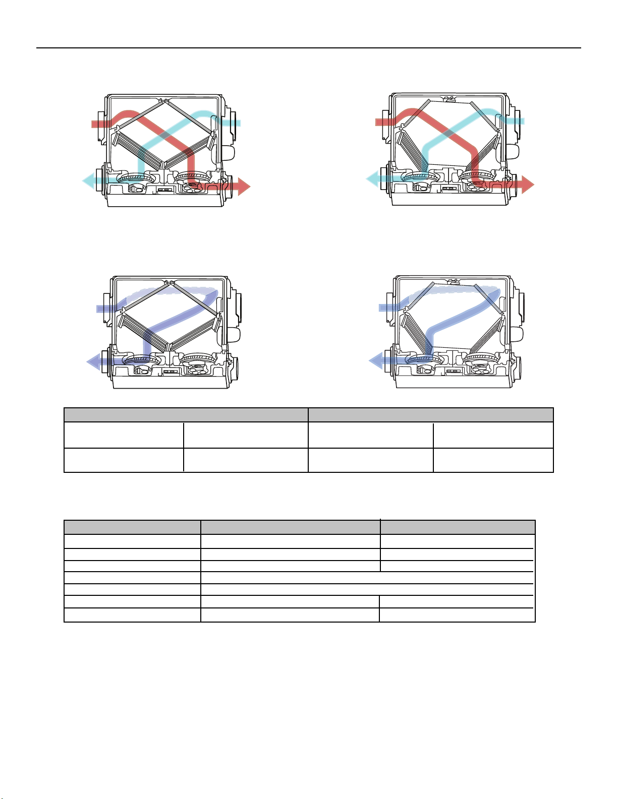
1. TECHNICAL DATA
1.1 AIR DISTRIBUTION (NORMAL OPERATION)
HRV ERV
1.2 A
IR DISTRIBUTION (RECIRCULATION OR DEFROST MODE)
Celcius (°C)
-5 to -27
-27 and less
Fahrenheit (°F)
23 to -17
-17 and less
Defrosting (min.)
9
10
Operation time (min.)
between each defrost cycle
23
22
Outside Temperature HRV and ERV Defrost Cycles
- 4 -
EXHAUST AIR
-
FROM BUILDING
FRESH AIR
TO BUILDING
EXHAUST AIR-
FROM BUILDING
FILTERED AIR
TO BUILDING
E
XHAUST AIR
-
FROM BUILDING
F
ILTERED AIR
TO BUILDING
EXHAUST AIR
FROM BUILDING
FRESH AIR
TO BUILDING
FRESH AIR
FROM OUTSIDE
E
XHAUST AIR
TO OUTSIDE
FRESH AIR
FROM OUTSIDE
EXHAUST AIR
TO OUTSIDE
1.3 SPECIFICATIONS
Weight
Oval Ports
Drain Diameter
42 lb (19 kg)
Fit 5” (127 mm) ducts
1/2” (12 mm)
45 lb (20.4 kg)
Fit 5” (127 mm) ducts
N/A
Installation Chains, springs and hooks (provided with the unit).
Motor Speeds High and low speed
Electrical supply 120 V, 60 Hz 120 V, 60 Hz
Power Consumption 150 watts 160 watts
Model HRV ERV
VF0038
VF0036
VF0039
VF0037
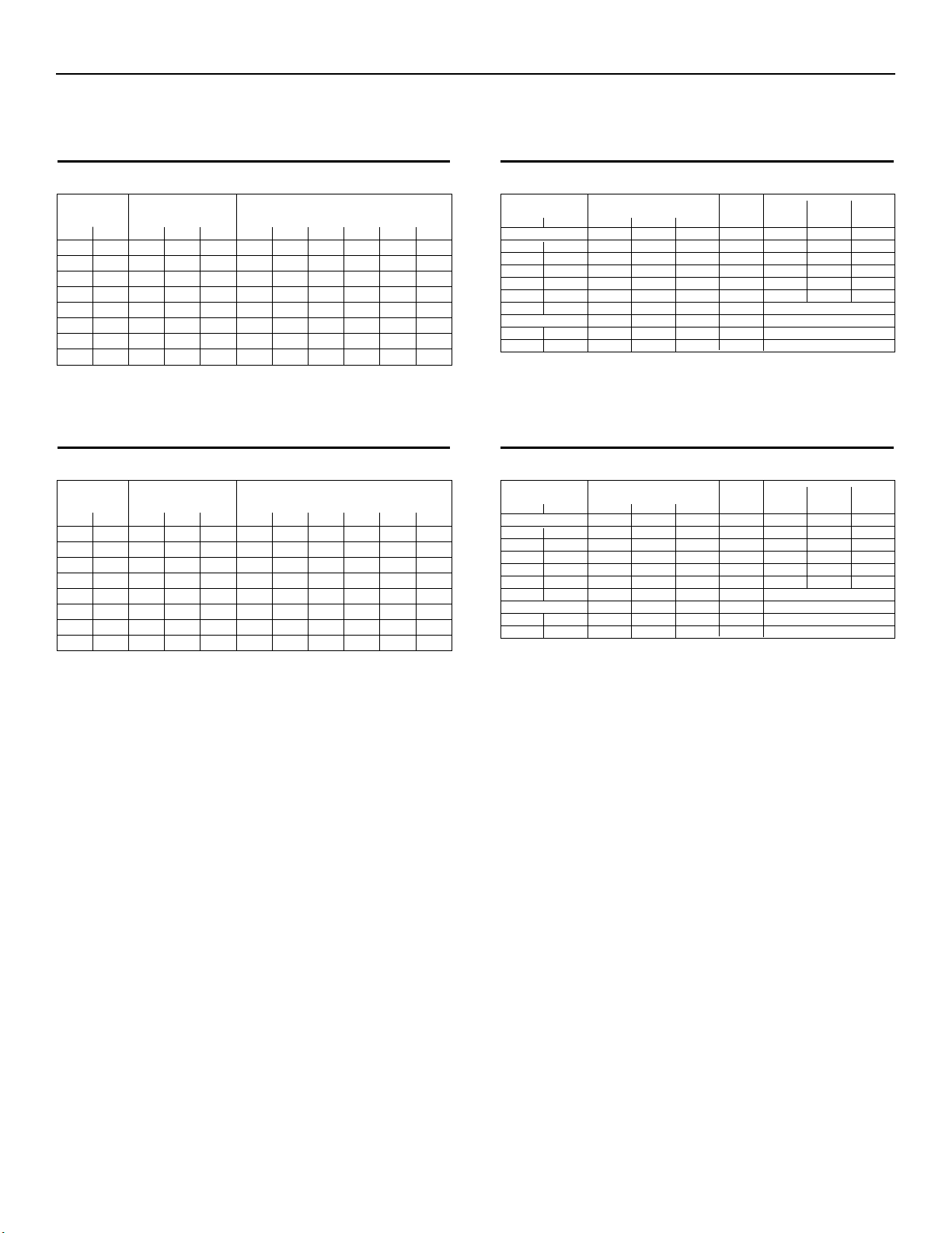
1.4.1 HRV UNITS
1. TECHNICAL DATA (CONT’D)
1.4 P
ERFORMANCE CHARTS
Ventilation Performance
NOTE: A
LL SPECIFICATIONS ARE SUBJECT TO CHANGE WITHOUT NOTICE
.
SUPPLY POWER SENSIBLE APPARENT
LATENTRECOVERY/
TEMPERATURE NET AIR FLOW CONSUMEDRECOVERY SENSIBLE MOISTURE
WATTS EFFICIENCY
EFFECTIVENESS
TRANSFER
68
82
116
110
66
65
59
55
78
76
68
81
0.07
0.04
0.04
0.08
Not tested
-
C°
0
0
0
-25
+35
F°
+32
+32
+32
-13
+95
l/s
23
30
44
30
-
-
cfm
48
63
93
63
-
-
m3/h
82
108
157
108
-
-
COOLING
HEATING
TOTAL RECOVERY EFFICIENCY
EXT STATIC NET SUPPLY GROSS AIR FLOW
PRESSURE AIR FLOW SUPPLY EXHAUST
Pa
25
50
75
100
125
150
175
200
in.w.g.
.1
.2
.3
.4
.5
.6
.7
.8
l/s
52
50
48
45
43
41
38
35
cfm
110
106
101
96
92
87
81
75
m3/h
187
180
173
162
155
148
137
126
l/s
52
50
48
46
43
41
38
36
cfm
110
106
102
97
92
87
81
76
m3/h
187
180
173
166
155
148
137
130
l/s
58
55
53
50
49
45
43
40
cfm
122
116
113
107
103
96
91
85
m3/h
205
198
191
180
173
162
155
144
Energy Performance
1.4.2 ERV UNITS
Ventilation Performance
NOTE: A
LL SPECIFICATIONS ARE SUBJECT TO CHANGE WITHOUT NOTICE
.
SUPPLY POWER SENSIBLE APPARENT
LATENTRECOVERY/
TEMPERATURE NET AIR FLOW CONSUMEDRECOVERY SENSIBLE MOISTURE
WATTS EFFICIENCY
EFFECTIVENESS
TRANSFER
70
85
127
102
67
65
61
56
82
77
73
78
0.60
0.54
0.49
0.50
49
68
C°
0
0
0
-25
+35
F°
+32
+32
+32
-13
+95
l/s
22
30
45
30
23
-
cfm
46
64
91
64
46
-
m
3
/h
79
108
155
108
166
-
COOLING
HEATING
TOTAL RECOVERY EFFICIENCY
EXT STATIC NET SUPPLY GROSS AIR FLOW
PRESSURE AIR FLOW SUPPLY EXHAUST
Pa
25
50
75
100
125
150
175
200
in.w.g.
.1
.2
.3
.4
.5
.6
.7
.8
l/s
55
53
50
49
46
44
42
39
cfm
116
113
107
104
98
94
88
82
m3/h
197
192
182
177
166
160
150
139
l/s
56
55
52
50
48
46
43
40
cfm
119
116
111
107
101
97
91
84
m3/h
202
197
189
182
172
165
155
143
l/s
59
57
54
53
50
47
45
42
cfm
125
121
115
112
105
100
95
90
m3/h
212
206
195
190
178
170
161
153
Energy Performance
- 5 -
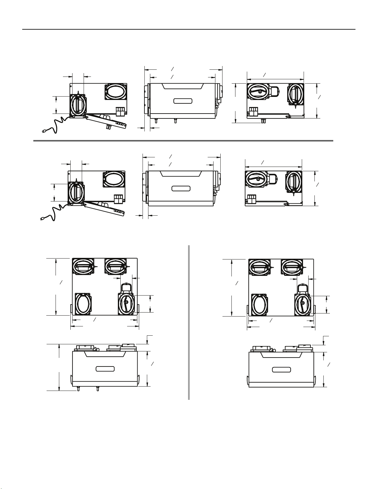
1. TECHNICAL DATA (CONT’D)
1.5 DIMENSIONS
1.5.1 D
IMENSIONS FOR PORTS ON
SIDES UNITS
HRV
ERV
1.5.2 DIMENSIONS FOR PORTS ON TOP UNITS
HRV ERV
1.6 C
ONTROLS AND LINKAGE POSSIBILITY
M
AIN CONTROL
• VT4W
A
UXILIARY CONTROLS
• 20-MINUTE PUSH BUTTON TIMER
• 60-MINUTE CRANK TIMER
• H
UMIDITY CONTROL
L
INKAGE POSSIBILITY
• AIR HANDLER INTERLOCK
(USED WITH FORCED AIR SYSTEM)
- 6 -
4’’ (102 mm)
6’’ (152 mm)
VK0055
4’’ (102 mm)
6’’ (152 mm)
1
27 16” (688 mm)
9
22
16” (574 mm)
2” (51 mm)
1
27 16” (688 mm)
9
16” (574 mm)
22
13¾”
(349 mm)
13
19 16” (503 mm)
13
19 16” (503 mm)
3
12 16”
(310 mm)
3
12 16”
(310 mm)
VK0057
13
19 16”
(503 mm)
9
22
16” (574 mm)
23 ¾” (603 mm)
16 ¼”
(413 mm)
VK0056
2” (51 mm)
4’’ (102 mm)
6’’ (152 mm)
2½”
(64 mm)
3
16”
12
(310 mm)
13
19 16”
(503 mm)
VK0058
9
22
16” (574 mm)
23 ¾” (603 mm)
4’’ (102 mm)
6’’ (152 mm)
2½”
(64 mm)
3
16”
12
(310 mm)
2.3 SIMPLIFIED INSTALLATION (CONNECTION TO A FORCED AIR SYSTEM)
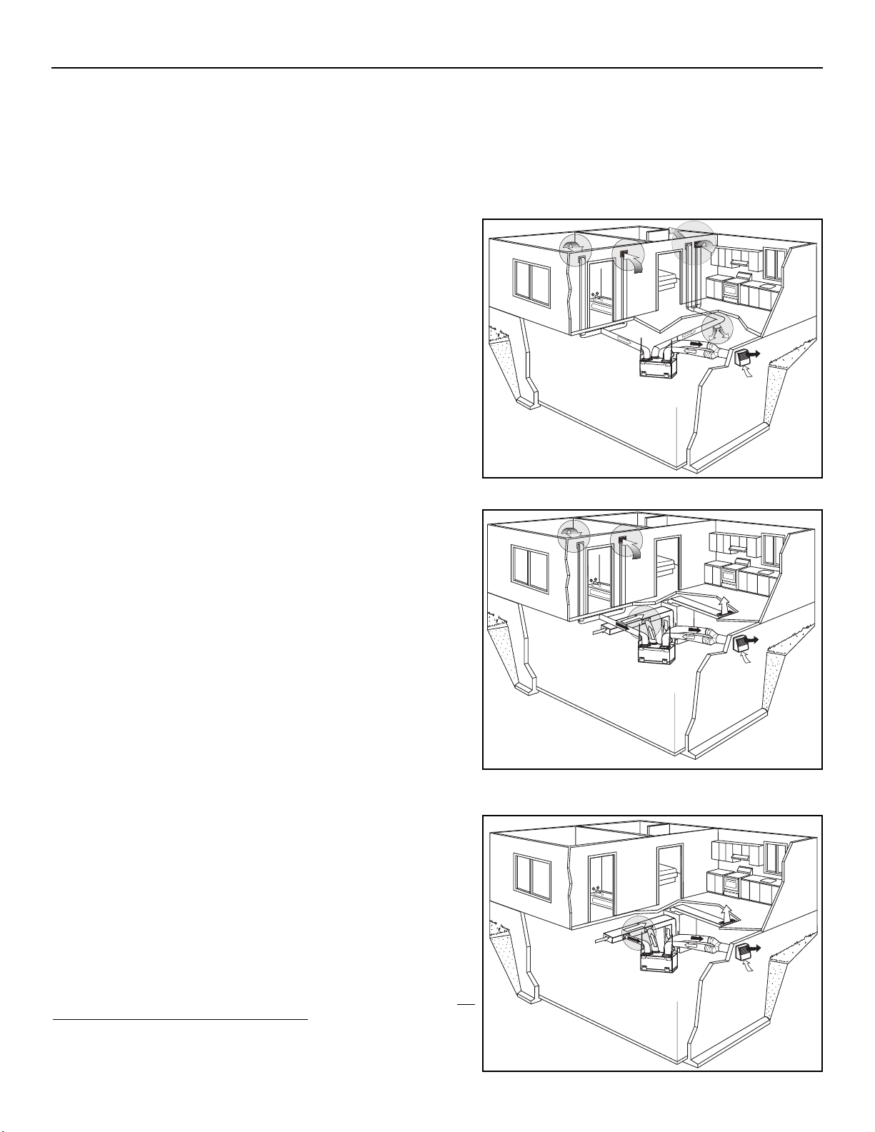
2. TYPICAL INSTALLATIONS
Installations may vary according to the type of unit and the ports configuration (top or sides). Use the following illustrations as guidelines
to help you decide on how the unit will be installed.
All the units should be hung from the joists.
In every case, bathroom fans and a range hood should be used to exhaust stale air. Also, for homes with more than one level, we
recommend one exhaust register at the highest level.
There are 3 installation methods: Fully ducted, Central Draw Point and Simplified Installation.
NOTE: An electrical outlet has to be available within 3 feet of the unit.
2.1 FULLY DUCTED SYSTEM (PRIMARILY FOR HOMES WITH RADIANT HOT WATER OR ELECTRIC BASEBOARD HEATING.)
2.2 C
ENTRAL DRAW POINT (CONNECTION TO A FORCED AIR SYSTEM.)
For this type of installation, it is not essential that the forced air system
blower runs when the unit is in operation, but we recommend it.
NOTE: Home with multiple forced air systems should have one unit on
each system.
Stale air coming from the registers located at the highest level of the house
is exhausted to the outside. Fresh air from outside is filtered and supplied
by the register located in the lowest liveable level.
Homes with more than one level require at least one exhaust register at the
highest level.
See figure at right.
Stale air coming from the registers located at the highest level of the house
is exhausted to the outside. Fresh air from outside is filtered and supplied
to the return (plenum) or the supply duct of the forced air unit. See figure
at right.
Stale air is exhausted to the outside. Fresh air from outside is filtered and
supplied to the return (plenum) or the supply duct of the forced air unit. See
figure at right.
NOTE: It is possible to connect the outside fresh air duct to the supply
duct of the forced air unit.To do so, the Automatic fresh air bypass
must be used (part #: 15391). (See installation sheet included with
the Automatic fresh air bypass).
To avoid cross-contamination and achieve the highest efficiencies, the
Automatic fresh air bypass (part #15391) must be installed. If not, the
f
orced air system blower must always be ON.
NOTE: Home with multiple forced air systems should have one unit on
each system.
- 7 -
VH0055
VH0056
VH0057
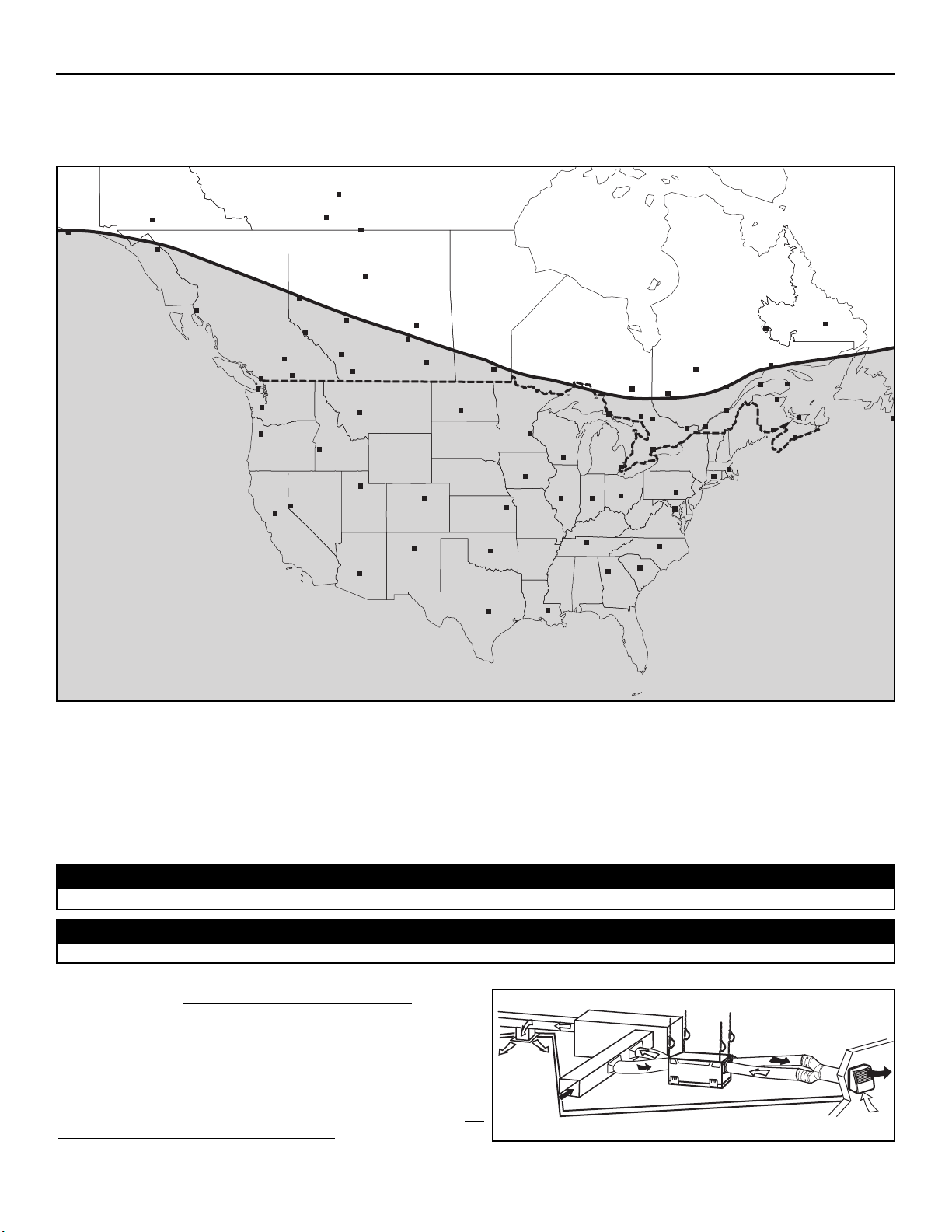
2. TYPICAL INSTALLATIONS (CONT’D)
The ERV units are created to meet specific requirements related to geographical locations. Take a look at the map below; the shaded
area shows the limits where the ERV unit can be installed. However, there is no geographical limitation for installing an HRV unit.
NOTE:The ERV unit is designed to assist in the management of humidity introduced into the home.
During cooling season, in extreme humidity conditions, the use of additional dehumidification unit may be required to quickly
remove all excess moisture. During heating season, in extreme dryness conditions, the use of a humidifier may be required if
the indoor air is still too dry.
ANCHORAGE
WHITEHORSE
JUNEAU
HAY RIVER
YELLOWKNIFE
Prince Rupert
GRANDE PRAIRIE
FORT MCMURRAY
FORT SMITH
EDMONTON
PRINCE ALBERT
SASKATOON
JASPER
KAMLOOPS
CALGARY
PENTICTON
REGINA
LETHBRIDGE
HELENA
VICTORIA
OLYMPIA
WINNIPEG
SALEM
BOISE
BISMARCK
SALT LAKE CITY
SAULT STE MARIE
ST. PAUL
DES MOINES
MADISON
TIMMINS
HARRISBURG
SACRAMENTO
DENVER
TOPEKA
SUDBURY
TORON TO
DETROIT
INDIANAPOLIS
SANTA FE
SPRINGFIELD
OKLAHOMA CITY
PHOENIX
COLUMBUS
NASHVILLE
ATLANTA
BATON ROUGE
AUSTIN
COLUMBIA
RALEIGH
WASHINGTON
OTTAWA
NORTH BAY
VAL-DOR
CHICOUTIMI
HARTFORD
CHIBOUGAMAU
MONTRÉAL
QUEBEC
BOSTON
GOOSE BAY
LABRADOR CITY
SEPT-ILES
MATANE
GASPÉ
BATHURST
ST-JOHN
HALIFAX
CHARLOTTETOWN
ST JOHN’S
RENO
2.4 INSTALLATION FOR ERV UNITS ONLY
2.4.1 GEOGRAPHICAL LOCATION
All 3 types of installations can be used in the attic (Fully ducted system, Central Draw Point or Simplified). The example shown below is
a Simplified installation (connection to a forced air system).
Stale air is exhausted to the outside. Fresh air from outside is filtered
and supplied to the return (plenum) of the forced air unit. See figure
at right.
NOTE: It is possible to connect the outside fresh air duct to the supply
duct of the forced air unit. To do so, the Automatic fresh air
bypass must be used (part #: 15205). (See installation sheet
included with the Automatic fresh air bypass).
To avoid cross-contamination and achieve the highest efficiencies, the
Automatic fresh air bypass (part #15205) must be installed. If not, the
forced air system blower must always be ON.
NOTE: Home with multiple forced air systems should have 1 unit on each system.
Due to the potential temperature difference between the attic and the rest of the house, all unit ducts must be insulated.
CAUTION
The attic temperature must always be above 0°C (32°F).
CAUTION
2.4.2 ERV U
NITS ATTIC INSTALLATION
- 8 -
VN0006
VH0058
 Loading...