


Broan BUEZ236WW, BUEZ136WW, BUEZ230SS, BUEZ121WW, BUEZ024WW Installation Manual
...
BUEZ0
HOOD
ECONOMY RANGE HOOD
INSTALLATION INSTRUCTIONS
READ AND SAVE THESE INSTRUCTIONS
!
INTENDED FOR DOMESTIC COOKING ONLY
WARNING
TO REDUCE THE RISK OF FIRE, ELECTRIC SHOCK, OR INJURY TO
PERSONS, OBSERVE THE FOLLOWING:
1. Use this unit only in the manner intended by the manufacturer. If you have
questions, contact the manufacturer at the address or telephone number
listed in the warranty.
2. Before servicing or cleaning unit, switch power off at service panel and
lock service panel to prevent power from being switched on accidentally.
When the service disconnecting means cannot be locked, securely fasten
a prominent warning device, such as a tag, to the service panel.
3. Installation work and electrical wiring must be done by a qualified
person(s) in accordance with all applicable codes and standards.
4. Sufficient air is needed for proper combustion and exhausting of
gases through the flue (chimney) of fuel burning equipment to prevent
backdrafting. Follow the heating equipment manufacturer’s guideline and
safety standards such as those published by the National Fire Protection
Association (NFPA), and the American Society for Heating, Refrigeration
and Air Conditioning Engineers (ASHRAE), and the local code authorities.
5. When cutting or drilling into wall or ceiling, do not damage electrical wiring
and other hidden utilities.
6. Ducted fans must always be vented to the outdoors.
7. Do not use this unit with any solid-state speed control device.
8. To reduce the risk of fire, use only metal ductwork.
9. Use with approved cord-connection kit only.
10.This unit must be grounded.
TO REDUCE THE RISK OF A RANGE TOP GREASE FIRE:
1. Never leave surface units unattended at high settings. Boilovers cause
smoking and greasy spillovers that may ignite. Heat oils slowly on low
or medium settings.
2. Always turn hood ON when cooking at high heat or when cooking flaming
foods.
3. Clean ventilating fans frequently. Grease should not be allowed to
accumulate on fan or filter.
4. Use proper pan size. Always use cookware appropriate for the size of
the surface element.
TO REDUCE THE RISK OF INJURY TO PERSONS IN THE EVENT OF A
RANGE TOP GREASE FIRE, OBSERVE THE FOLLOWING:*
1. SMOTHER FLAMES with a close-fitting lid, cookie sheet, or metal tray,
then turn off the burner. BE CAREFUL TO PREVENT BURNS. If the
flames do not go out immediately, EVACUATE AND CALL THE FIRE
DEPARTMENT.
2. NEVER PICK UP A FLAMING PAN - You may be burned.
3. DO NOT USE WATER, including wet dishcloths or towels - a violent
steam explosion will result.
4. Use an extinguisher ONLY if:
A. You know you have a Class ABC extinguisher and you already know how
to operate it.
B. The fire is small and contained in the area where it started.
C. The fire department is being called.
D. You can fight the fire with your back to an exit.
*Based on “Kitchen Firesafety Tips” published by NFPA.
BUEZ1
HOOD
BUEZ2
HOOD
!
CAUTION
1. For indoor use only.
2. For general ventilating use only. Do not use to exhaust hazardous or
explosive materials and vapors.
3. To avoid motor bearing damage and noisy and/or unbalanced impellers,
keep drywall spray, construction dust, etc. off power unit.
4. For best capture of cooking impurities, your range hood should be
mounted 20-25” above the cooking surface.
5. Please read specification label on product for further information and
requirements.
IMPORTANT: OBSERVE ALL GOVERNING CODES AND
ORDINANCES
Your range hood has been designed to filter out smoke, odors, and grease
which rise from the cooking surface. Before you begin the installation be
sure that all parts and accessories are removed from carton. For best results
and ease in the installation of this range hood, read the instructions sheet
to become familiar with the step-by-step installation.
TOOLS AND MATERIALS REQUIRED
Drill, electric or ratchet drive
1/8" drill bit for drilling pilot holes
7/64" drill bit to drill holes for EZ1 brackets mounting screws
1-1/4" wood bit for drilling electrical wiring access hole
One common head screwdriver for securing hood mounting screws to
the cabinet and hood sheet metal parts
Pliers for opening knockouts
Pencil, rule and level for marking cabinet locations
Saber saw or keyhole saw for cutting the wall or cabinet openings
Metal snips, duct tape, duct (with elbows and transition, if necessary),
roof cement or caulk, and roof or wall cap, as required
Electrical wiring and supplies of type to comply with local codes
The following materials are required only for installation on recessed bottom
kitchen cabinets:
Two 1" x 2" x 12" (approximate length) wood strips (purchase locally)
Four 1-1/4" long flat head wood screws (purchase locally)
INSTALLER:
LEAVE THIS MANUAL WITH THE HOMEOWNER.
HOMEOWNER:
USE AND CARE INSTRUCTIONS ON PAGE 4.
Register this product at
www.broan.com/register.
To order Service Parts: go to www.broan.com
PREPARING THE HOOD
1. Unpack hood and check contents. You should receive:
1 – Aluminum filter (BUEZ0 and BUEZ2 hoods only)
1 – 3-1/4" x 10" damper/duct connector, mounted inside of hood for
shipping only (BUEZ0 hood only)
1 – Ductfree filter (BUEZ1 hood only)
1 – Installation parts bag (under wiring box cover)
1 – Set of EZ1 brackets (under wiring box cover)
ALUMINUM
FILTER (BUEZ0
& BUEZ2 HOODS
ONLY)
WIRING BOX COVER
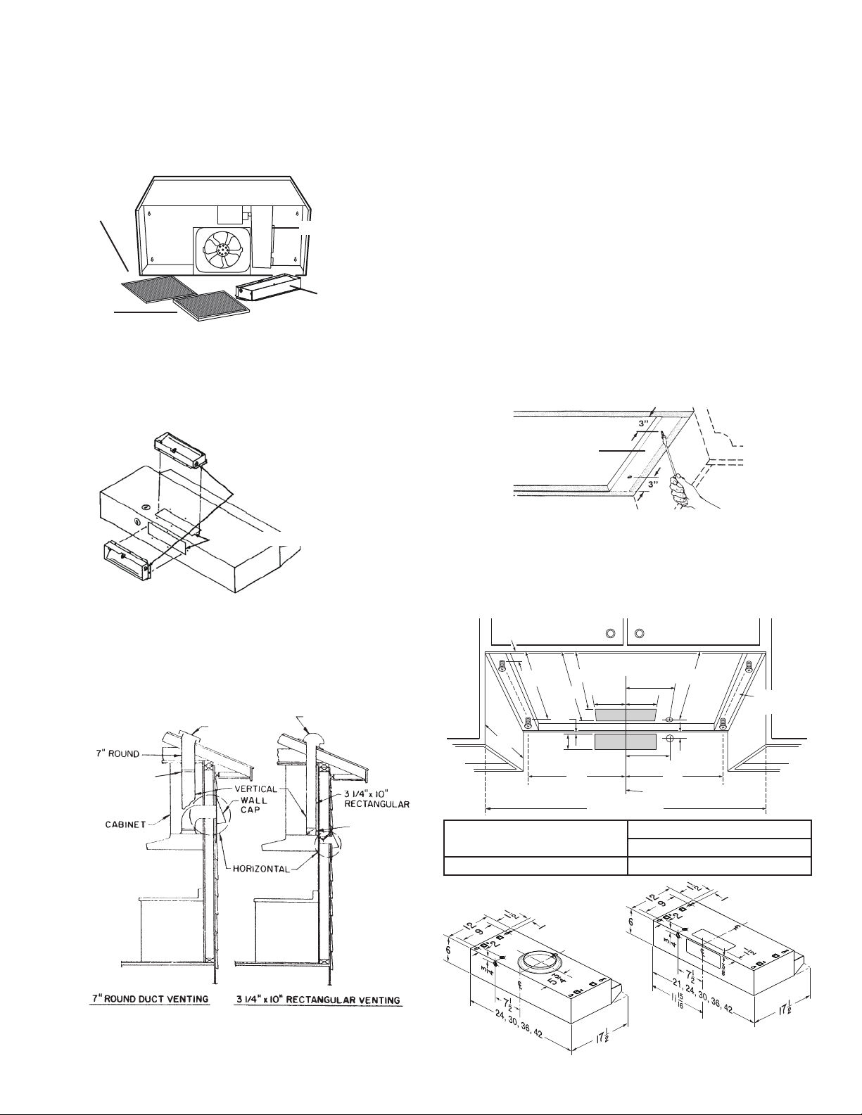
Ducting directly through the wall (for range hoods mounted on an exterior
wall). Shown are two ways to duct through an outside wall. If a wall cap
is used directly off the back of the hood, special care must be taken to
make sure that the damper in the damper/duct connector on the hood
and damper in the wall cap do not interfere with each other when the
hood is operating. This could result in either inadequate air delivery or
back drafts. If this condition does exist, remove the hood damper flap.
Sometimes when using a wall cap, it is easier to duct vertically and then
use an elbow.
Start at the exterior and run ductwork back to the range hood. For best
performance, use the shortest possible duct run and a minimum number
of elbow. Tape all duct connections using metal foil duct tape.
PREPARING THE INSTALLATION
DUCTFREE
FILTER (BUEZ1
HOOD ONLY)
DAMPER/DUCT CONNECTOR
(BUEZ0 HOOD ONLY)
2. Remove wiring box cover. Remove EZ1 brackets and parts bag from
behind wiring box.
3. Remove top or rear electrical knockout. Install an appropriate strain relief.
4. BUEZ0 hood only: Remove rear or top duct knockout. Install damper/
duct connecter over opening made. Use 2 no. 8B sheet metal screws
provided.
HINGE PINS
DUCT KNOCKOUTS
PLANNING DUCTWORK INSTALLATION
This section is for BUEZ0 and BUEZ2 hoods only. For BUEZ1hoods,
skip this section and go to "Preparing the Installation Location".
Begin planning ductwork by deciding where duct will run between hood
and outside. For best performance, use shortest possible duct run and a
minimum number of elbows. There are several choices.
ROOF CAP
DAMPER
(INCLUDED)
REMOVE THE
HOOD DAMPER
FLAP IF IT
INTERFERES
WITH THE WALL
CAP DAMPER
BP87Q DAMPER (NOT
INCLUDED) LOCATED
AT LEAST 6" FROM
HOOD IN VERTICAL
SECTION OF DUCT
ROOF CAP
LOCATION
NOTE: MOUNT HOOD SO THAT BOTTOM OF HOOD IS 18" TO 24" ABOVE
COOKING SURFACE. TOP FRONT OF HOOD SHOULD BE FLUSH WITH
FRONT OF CABINET FRAME.
IF DISTANCE BETWEEN WALL AND FRONT OF CABINET FRAME IS
MORE THAN 12", THERE WILL BE A SPACE BETWEEN BACK OF HOOD
AND WALL. THIS IS NORMAL.
OMIT STEP 1 IF HOOD WILL BE INSTALLED UNDER CABINETS WITH
FLUSH BOTTOM OR INSTALLED USING THE EZ1 BRACKETS.
FILLER STRIP
1. For cabinets with recessed bottoms only, if not using EZ1 brackets: Install
wood filler strips on each side of recessed area under cabinet. Use two
1" x 2" strips cut to length (use thicker strips if necessary). Fasten strips
with wood screws about 3" in from each end.
2. Measure and mark the following:
a.) Electrical wiring opening in wall or cabinet.
b.) Duct opening in wall or cabinet (BUEZ0 and BUEZ2 hoods only).
1
1
/ 2 ”
/ 2 ”
10
7
6
/ 8 ”
5
/ 8 ”
1
7
1
5
/ 4 ”5 1/ 4 ”
10
1
1/8 ”
12”
7
3
/ 8 ”
1
7
/ 2 ”
A
CENTER LINE
HOOD WIDTH
A = 7-15/16” FOR 21” RANGE HOODS
B = 10-15/16” FOR 21” RANGE HOODS
A & B = 10-15/16” FOR 24” RANGE HOODS A & B = 19-15/16” FOR 42” RANGE HOOD
BUEZ2 BUEZ0
A & B = 13-15/16” FOR 30” RANGE HOOD
A & B = 16-15/16” FOR 36” RANGE HOOD
/ 2 ”
3/4 ”
B
7
9
/ 8 ”
FILLER
STRIP
BUEZ2 BUEZ0
*
* Duct cutouts not centered
on 21” hood width.
2

WARNING: WHEN CUTTING OR DRILLING INTO WALL OR CABINET,
BE CAREFUL NOT TO CUT EXISTING ELECTRICAL WIRING.
3. Drill 1-1/4" electrical wiring opening in wall or cabinet bottom.
4. Drill four pilot holes in corners of marked duct opening and cut opening
with saber or keyhole saw (BUEZ0 and BUEZ2 hoods only).
INSTALLING THE RANGE HOOD
This manual covers 2 kinds of installation: the standard (without EZ1
brackets) and the EZ1 one-person installation system. If the cabinet is
wider than the range hood width, please use the standard installation
method. For the standard installation, go to page 4.
EZ1 ONE-PERSON INSTALLATION SYSTEM
Use the appropriate brackets according to the kitchen cabinet type. Refer
to the marking on the brackets to determine the correct installation side
and orientation.
X
FRAMELESS
CABINET
Y
Z
FRAMED CABINET
XY
7/64”
Z
Mate the corresponding bracket to the cabinet side frame, while placing
rear end of bracket against the wall. Use a pencil to mark 3 holes (there
are 6 holes but only 3 are necessary).
Remove the bracket. Using a 7/64” drill bit, drill 3 holes where marked.
Assemble the bracket to the side frame using a Phillips screwdriver and
3 provided round head no. 8 x 5/8” wood screws. Repeat for the other
side frame.
3 X
[ \
7/64”
Align the corresponding bracket to the cabinet side, while placing rear
end of bracket against the wall. Draw a line on the outer edge of the
bracket (as shown).
Slide the bracket towards the center of cabinet and align the outside
edge of the bracket with the marked line, keeping the rear end edge
leaning on the wall.
Use a pencil to mark 3 holes.
Remove the bracket. Using a 7/64” drill bit, drill 3 holes where marked.
Assemble the bracket to the cabinet bottom using a Phillips screwdriver
and 3 provided countersunk wood screws. Repeat for the other cabinet
side.
The following procedure applies to both framed or frameless
cabinet installations.
HORIZONTAL EXHAUST INSTALLATION ONLY
1. Pull house power cable out.
2. Temporarily hang the hood on the brackets using its 2 recessed REAR
HOLES (A and B). While holding the hood, run the house power cable
into the hood through the strain relief previously installed.
3. Unhook the rear holes from the brackets and hang the hood using its
2 recessed FRONT HOLES. While holding the hood, attach the power
cable to the hood using the strain relief.
A
B
VERTICAL EXHAUST INSTALLATION ONLY
1. Pull house power cable out.
2. Hang the hood on the brackets using the 2 recessed FRONT HOLES.
While holding the hood, run the house power cable into the hood
through the strain relief previously installed. Attach power cable to the
hood.
3

For framed cabinet, secure the hood to the EZ1 brackets using
4 no. 8-18 x 1/2” metal screws (included). Insert 2 screws per side, in the
slots.
For frameless cabinet, secure the hood to the cabinet using 4 no. 8 x 5/8”
round head wood screws (included). Insert 2 screws per side, in the slots.
FRAMED
CABINET
FRAMELESS
CABINET
FINALIZE THE INSTALLATION
1. Install light bulb (75 watts maximum). For easier installation, squeeze
plastic lens and remove it from hood. Remember to reinstall lens.
SOCKET
METAL
SCREWS
SCREWS
STANDARD INSTALLATION
WOOD
1. Hold hood up against cabinet bottom and trace keyhole slots onto cabinet
bottom or filler strips.
KEYHOLE SLOT OUTLINE
FILLER
STRIPS
2. Screw the four supplied screws for mounting the hood into the exact center
of the narrow end of the keyhole slots marked underneath the cabinet.
Allow 3/8" of the screws to project, so the hood can be fitted into place.
3. Run electric wiring through hole drilled in wall or cabinet. Split wiring for
6" and run the house power cable into the hood through the strain relief
previously installed. Attach power cable to the hood.
4. Position hood so that:
a.) Large part of keyhole slots fit over hood mounting screws.
b.) Damper/duct connector slides into ductwork (BUEZ0 hoods only)
5. Adjust hood so that hood front is flush with cabinet frame.
6. Tighten hood mounting screws firmly.
CONNECT THE WIRING
WARNING: TURN OFF THE PROPER CIRCUIT AT THE SERVICE
ENTRANCE BEFORE WIRING THIS RANGE HOOD. ALL ELECTRICAL
CONNECTIONS MUST BE MADE IN ACCORDANCE WITH LOCAL
CODES, ORDINANCES, OR NATIONAL ELECTRICAL CODE. IF YOU ARE
UNFAMILIAR WITH METHODS OF INSTALLING ELECTRICAL WIRING,
SECURE THE SERVICES OF A QUALIFIED ELECTRICIAN.
2. Turn on power and check operation of fan and light. Make sure that
damper operates freely (BUEZ0 hoods only).
USE AND CARE
SWITCHES
The fan and light are each controlled by a rocker switch. The light switch has
two positions, “ON” and “OFF”. The fan switch has three positions - “HIGH”,
“LOW” and “OFF”. ( “OFF” is the middle position.)
FILTERS
BUEZ0, BUEZ2 Hoods Only:
Remove aluminum filter by turning filter retainer to one side. Filter should
be washed once a month in a hot detergent solution. Aluminum filters are
dishwasher safe. When installing filter, make sure that filter slides under
retaining tabs on back of fan housing. Turn filter retainer so that arrows on
retainer point toward front and back of hood.
FILTER RETAINER
FILTER
TABS
BUEZ1 Hoods Only:
The BUEZ1 hood is equipped with a ductfree filter. Remove filter by turning
filter retainer to one side. (see illustration above) The ductfree filter is not
washable, and will last up to twelve months with normal use. Replace the filter
when colored side becomes noticeably dirty or discolored.
When installing filter, make sure that filter slides under retaining tabs on back
of fan housing. MAKE SURE THAT COLORED SIDE OF FILTER IS NEXT
TO FAN WHEN FILTER IS INSTALLED. Turn filter retainer so that arrows
on retainer point toward front and back of hood.
WARNING
ALWAYS DISCONNECT ELECTRIC POWER BEFORE SERVICING
RANGE HOOD.
1. Make electrical
connection using wire
nuts to connect WHITE
wire to WHITE, BLACK
wire to BLACK, and
GREEN or bare wire
to GREEN ground
screw provided.
2. Replace wiring box
cover and screw, taking
care not to pinch wires.
GREEN
GROUND SCREW
GROUND WIRE (BARE
OR GREEN WIRE)
STAR LOCKNUT
BLACK WIRES
WHITE WIRES
GROUNDING
BRACKET
CLEANING
Clean your hood with a mild detergent suitable for painted surfaces. DO NOT
USE ABRASIVE CLOTH, STEEL WOOL PADS OR SCOURING POWDERS.
Fan assembly is permanently lubricated, and never needs oiling. Clean
motor with a damp cloth and grease-cutting detergent when a heavy coating
of grease has accumulated.
4
 Loading...