


 Loading...
Manufacturers > EMC Partner
Categories > EMC Test Equipment > RTCA \ DO-160 > EMI \ EMC Equipment for Military Standards EMC Partner MIG2000-6 Modular Impulse Generator Product Page
LARGEST RANGE OF IMPULSE TESTERS UP TO 100KV/100KA
How-to Video
Technical Specification
E-MIG2000-6 revised: 07. May 2009
1 MIG Tester Type MIG2000-6
1 |
MIG Tester Type MIG2000-6 |
1 |
||
2 |
General |
|
2 |
|
|
2.1 |
Brief description of the MIG2000-6 system |
2 |
|
|
2.1.1 |
Serial Injection |
2 |
|
|
2.1.2 |
Parallel injection |
2 |
|
|
2.1.3 |
Impulse Synchronization |
2 |
|
|
2.2 |
Standards and applications |
3 |
|
|
2.3 |
Overview of the EMCP MIG2000-6 Test System |
3 |
|
3 Generator circuit, wave shapes definitions |
4 |
|
3.1 |
Wave shape definition MIL-STD-461F CS106 |
4 |
3.2 |
Wave shape definition MIL-STD-461F CS115 |
4 |
3.3 |
Wave shape definition MIL-STD-461F CS116 |
4 |
3.4 |
Wave shape definition MIL-STD-1275 |
5 |
3.5 |
Wave shape definition Euro Fighter CS-EFA-4 “Fast & Slow” |
5 |
3.6 |
Wave shape definition Airbus AMD24-C |
6 |
3.7 |
Wave shape definition DO160 section 17 |
6 |
3.8 |
Wave shape definition DO160 section 19 |
6 |
3.9 |
Mechanical dimensions, climatic conditions |
7 |
4 Technical data |
8 |
|
4.1 |
Voltage Spike waveform MIL-STD-461F CS106 |
8 |
4.2 |
Rectangular waveform MIL-STD-461F CS115 |
8 |
4.3 |
Damped oscillatory MIL-STD-461F, CS116 |
8 |
4.4 |
Ringwave MIL-STD-1275 |
9 |
4.5 |
Airbus AMD24-C |
9 |
4.6 |
Euro Fighter Slow & Fast |
10 |
4.7 |
DO160 section 17 |
10 |
4.8 |
DO160 section 19 |
10 |
5 Accessories and Options |
11 |
|
5.1 |
System Accessories |
11 |
5.2 |
Accessories to all MIG and TRA Testers |
13 |
Introduction |
|
|
The MIG2000-6 is available with a range of plug-in modules capable of generating damped oscillatory and double exponential pulses in accordance with MIL-STD-461E: CS115, CS116 and other standards. MIG2000-6 system comprises the impulse generator together with necessary injection probes (couplers). Because this is a complete system, waveforms are guaranteed at the injection point. The MIG "Modular-Impulse-Generator" is a flexible kit system, ready to quote tailored generators for special test applications. The MIG is a further innovative solution from EMC PARTNER AG to meet customer requests.
MIG generators are modern test equipment with the following features:
•Solid state impulse switch and solid state polarity change (no mechanical switch, no spark gaps or tubes) - advantages: low jitter, no high frequency switching noise,
•Microprocessor menu controlled, printer port and RS232 remote control
•Safety in accordance with VDE 0104 (safety circuit, connector for warning lamp)
•Integrated peak measurement for voltage and current. Peak display and monitor output for v,i
•Windows software for PC control available. Software versions see EMCP web site
07 . 05 . 2009 |
EMC PARTNER AG |
1/ 14 |

TECHNICAL SPECIFICATION E-MIG2000-6
2 General
2.1 Brief description of the MIG2000-6 system
MIG2000-6 is a versatile, flexible system which uses modules to provide a wide variety of impulse types for many applications.
The principle application is MIL-STD-461F, CS106, CS115 and CS116 testing. Apart from the MIG2000-6 mainframe, this requires:
•Plug-in module CS115
•Plug-in module CS116 10K10M
•Plug-in module CS116 30M100M
•Plug-in module CS106
•Injection coupler CN-MIG-BT for the frequency range 10 kHz up to 10 MHz
•Injection coupler CN-MIG-BT2 for the frequency range 10 MHz up to 100 MHz
•Calibration set-up VERI-MIL2 in accordance with MIL-STD-461E
In addition to MIL-STD-461F, modules are available for applications as below:
•NATO-SLOW-10u, 2/10us
•NATO-FAST-150n, 0.15/10us
•Fx-DO-160-S17, 2/10us
•Fx-DO-160-S19, 250kHz burst
•Fx-MIL1275, Ringwave
•Fx-AMD24C, 2/10us + 2/50us + 2/100us + 2/200us + 2/400us
Customised frequency plug-in modules (e.g. platform resonances) can be ordered separately
2.1.1 Serial Injection
Serial injection is used to superimpose impulses onto an equipment cabling. These tests are applicable to all waveform types. Together with the MIG generator, coupling transformers such as the CN-MIG-BT and CN-MIG-BT2 make a complete system to couple pulses into the Equipment Under Test (EUT).
Because coupling transformers are used for serial injection tests, external verification equipment is required to ensure that waveforms and amplitudes are correct at the point of injection.
2.1.2 Parallel injection
Parallel injection is an alternative method to serial injection which requires direct connection of the impulse generator to equipment housing or cables. Because the generator could be connected to AC or DC power lines, the generator impulse circuits must be protected against current flowing from the EUT.
2.1.3 Impulse Synchronization
For all impulses applied on power lines, synchronization at 90° the power frequency must be achieved. MIG2000-6 uses an external SYNC adapter to provide synchronization up to 400Hz.
07 . 05 . 2009 |
EMC PARTNER AG |
2/ 14 |

TECHNICAL SPECIFICATION E-MIG2000-6
2.2 Standards and applications
MIL-STD-461F, Department of Defense Interface Standard.
Requirements for the control of electromagnetic interference characteristics of subsystems and equipment
MIL-STD-1275D – Department of Defense Interface Standard.
Characteristics of 28 Volt DC Eelctrical Systems in Military Vehicles.
Airbus A400M AMD24-C
DO160 Environmental conditions and Test Procedures for Airborne Equipment
Section17 – Voltage Spike
DO160 Environmental conditions and Test Procedures for Airborne Equipment
Section19 – Induced Signal Susceptibility
Euro Fighter SPE-J-000-E-1000. CS-EFA-4, Imported Transients conducted Susceptibility, Imported Spikes and Transients, Time Domain, Power Lines.
2.3 Overview of the EMCP MIG2000-6 Test System
MIG2000-6 Module |
CS106 |
CS115REC |
CS116-10K10M |
CS11630M100M |
NATO-SLOW 10u |
NATO-FAST-150n |
Fx-DO-160-S17 |
Fx-DO-160-S19 |
Fx-MIL1275 |
Fx-AMD24C |
CN-MIG-BT |
CN-MIG-BT2 |
CN-MIG-BT4 |
SYNCH-ADAPTER |
VERI-MIL2 |
VERI-50 |
VERI5 |
DC S17 CL |
|
|
|
|
|
|
|
|
|
|
|
|
|
|
|
|
|
|
|
Standard |
|
|
|
|
|
|
|
|
|
|
|
|
|
|
|
|
|
|
MIL-STD-461 |
X |
|
|
|
|
|
|
|
|
|
X |
|
|
|
|
|
X |
X |
CS106 |
|
|
|
|
|
|
|
|
|
|
|
|
|
|
|
|
|
|
MIL-STD-461 |
|
X |
|
|
|
|
|
|
|
|
X |
|
|
|
X |
X |
|
|
CS115 |
|
|
|
|
|
|
|
|
|
|
|
|
|
|
|
|
|
|
MIL-STD-461 |
|
|
X |
|
|
|
|
|
|
|
X |
|
|
|
X |
X |
|
|
CS116 10kHz |
|
|
|
|
|
|
|
|
|
|
|
|
|
|
|
|
|
|
MIL-STD-461 |
|
|
X |
|
|
|
|
|
|
|
X |
|
|
|
X |
X |
|
|
CS116 100kHz |
|
|
|
|
|
|
|
|
|
|
|
|
|
|
|
|
|
|
MIL-STD-461 |
|
|
X |
|
|
|
|
|
|
|
X |
|
|
|
X |
X |
|
|
CS116 1MHz |
|
|
|
|
|
|
|
|
|
|
|
|
|
|
|
|
|
|
MIL-STD-461 |
|
|
X |
|
|
|
|
|
|
|
X |
|
|
|
X |
X |
|
|
CS116 10MHz |
|
|
|
|
|
|
|
|
|
|
|
|
|
|
|
|
|
|
MIL-STD-461 |
|
|
|
X |
|
|
|
|
|
|
|
X |
|
|
X |
X |
|
|
CS116 30MHz |
|
|
|
|
|
|
|
|
|
|
|
|
|
|
|
|
|
|
MIL-STD-461 |
|
|
|
X |
|
|
|
|
|
|
|
X |
|
|
X |
X |
|
|
CS116 100MHz |
|
|
|
|
|
|
|
|
|
|
|
|
|
|
|
|
|
|
MIL-STD-1275 |
|
|
|
|
|
|
|
|
X |
|
|
|
|
|
|
|
|
|
Euro Fighter |
|
|
|
|
X |
X |
|
|
|
|
X |
|
|
X |
|
X |
X |
X |
CS-EFA-4 |
|
|
|
|
|
|
|
|
|
|
|
|
|
|
|
|
|
|
Airbus |
|
|
|
|
|
|
|
|
|
X |
|
|
X |
X |
|
|
X |
X |
AMD24-C |
|
|
|
|
|
|
|
|
|
|
|
|
|
|
|
|
|
|
DO160 |
|
|
|
|
|
|
X |
|
|
|
X |
|
|
X |
|
X |
|
X |
section 17 |
|
|
|
|
|
|
|
|
|
|
|
|
|
|
|
|
|
|
DO160 |
|
|
|
|
|
|
|
X |
|
|
|
|
|
|
|
|
|
|
section 19 |
|
|
|
|
|
|
|
|
|
|
|
|
|
|
|
|
|
|
07 . 05 . 2009 |
EMC PARTNER AG |
3/ 14 |
TECHNICAL SPECIFICATION E-MIG2000-6
3 Generator circuit, wave shapes definitions
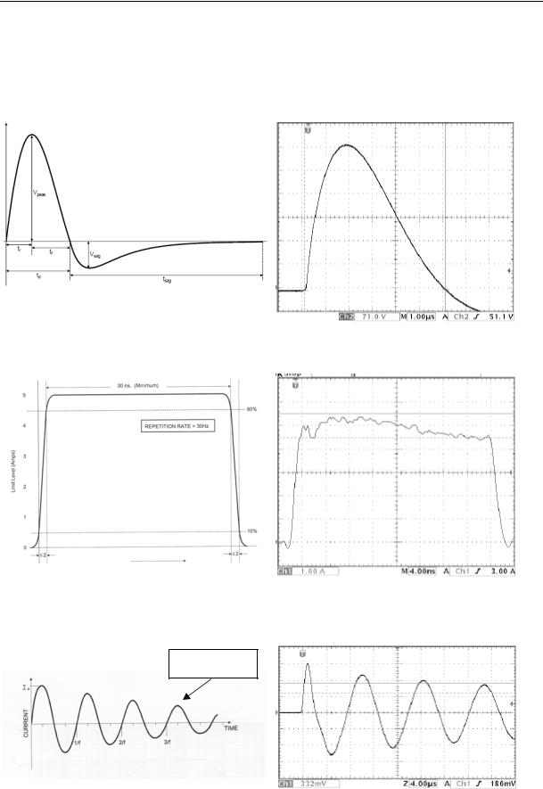
3.1 Wave shape definition MIL-STD-461F CS106
Standard waveform |
Waveform in the 5ohm load |
3.2 Wave shape definition MIL-STD-461F CS115
Standard waveform |
Waveform in the calibration fixture |
3.3 Wave shape definition MIL-STD-461F CS116
40 to 60% Ip
Standard waveform |
Waveform in the calibration fixture |
07 . 05 . 2009 |
EMC PARTNER AG |
4/ 14 |

TECHNICAL SPECIFICATION E-MIG2000-6
3.4 Wave shape definition MIL-STD-1275
Standard waveform |
Waveform at the EUT |
3.5 Wave shape definition Euro Fighter CS-EFA-4 “Fast & Slow”
Ts = 150ns
Standard waveform “Fast” |
Waveform at the EUT |
|
|
|
|
|
Ts = 10us |
|
|
|
|
Standard waveform “Slow” |
Waveform at the EUT |
07 . 05 . 2009 |
EMC PARTNER AG |
5/ 14 |
Loading...