


ESS-2000
Total Coordinator for EMC
Noise Laboratory Co., Ltd.
www.noiseken.co.jp
ESS-2000
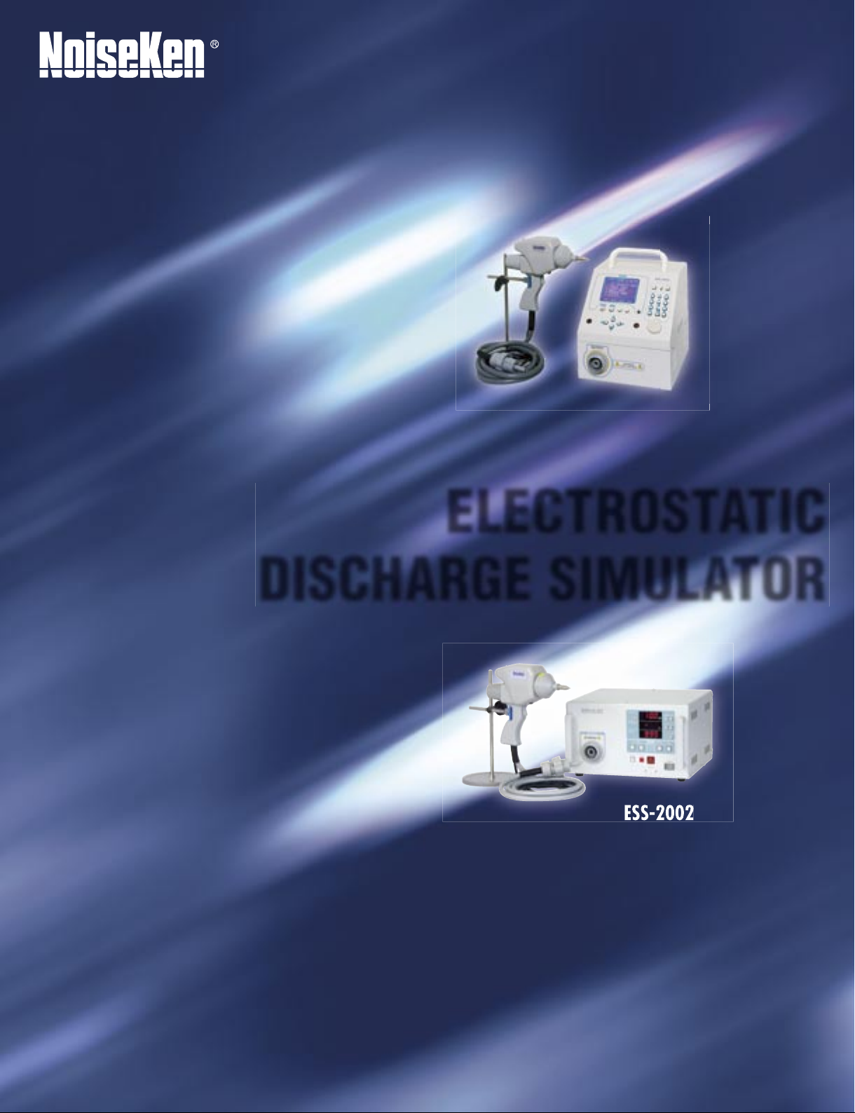
ELECTROSTATIC
DISCHARGE SIMULATOR
ESS-2002
Your products may
have passed the test
standards, but can
they survive in the real
world?
There are many ESD
standards for your
equipment.
Do those standards
really represent
the real world
phenomenon?
Reconsider your
testing program to
assure that your
products are really
ESD-immune.
Consider NoiseKen's
ESS series ESD
simulators to ensure
your products survival
in the real world.
The issue of product-level ESD (electrostatic discharge)
immunity has been attracting continued interest because it is
an important quality factor in equipment reliability, durability
and sometimes safety.
Generally, among the causes of equipment malfunction,
problems caused by ESD are the most diffi cult events against
which to incorporate protective measures, since the causal
relationship generally cannot be found easily. This often
makes ESD test programs extensive, complex, burdensome
and time-consuming. Thanks to the following benefi ts,
NoiseKen's ESS series ESD simulators are your best choice
whatever your requirements are, for design, qualifi cation,
production or diagnostic tests.
●
Meets and far exceeds the requirements in
EN/IEC61000-4-2
●
Up to 30kV output in both contact and air
discharges
●
A light weight discharge gun
●
Easily changeable capacitor and resistor units
●
A wide range of options
●
CE marked
Two models ESS-2000 and ESS-2002 are available.
The above-mentioned capabilities are common to them.
The ESS-2002 is the basic model with a built-in discharge
counter and time controller.
The ESS-2000 is the fully programmable menu-driven
simulator enabling users to carry out tests in a more automated
manner.
Electrostatic Discharge Simulator
2
Computer-Controlled ESD Simulator
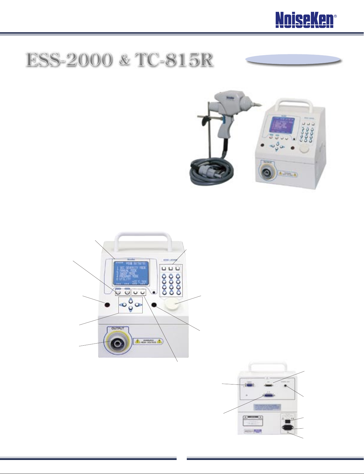
ESS-2000 & TC-815R
■
FEATURES
●
Fully programmable menu-driven simulator providing
four operation modes: IEC severity, Manual, Sweep, and
Program
●
A new level of ease of use and safety with the user
interface consisting of a 5-inch LCD, ten-key buttons,
rotary knob and others
●
Unique shape for operator's easy access to the control
and displays even when the unit is put on the fl oor level
(ground plane)
●
GP-IB interface
●
A wide variety of the dedicated options
(Gun stand in the photo is an optional accessory.)
■
CONTROLS, INDICATORS AND TERMINALS
Large LCD: Makes testing faster,
easier and more reliable
Start/Stop buttons
Cursor buttons
Infra-red reception
for Remote Controller and
Tem./Humidity Sensor
High Voltage Connector:
Used to connect discharge gun
Controls: Intuitive set-up can be done
Rotary Control
Warning Lamp:
Blinks when the HV circuitry is on.
Function keys
<Front Panel>
Printer terminal
GP-IB interface
AUX terminal
Warning Lamp
terminal
Power switch
AC Inlet
Earth terminal
<Rear Panel>
TC-815R
ESS-2000
Conforming to IEC61000-4-2
Electrostatic Discharge Simulator
3
ESS-2000
●
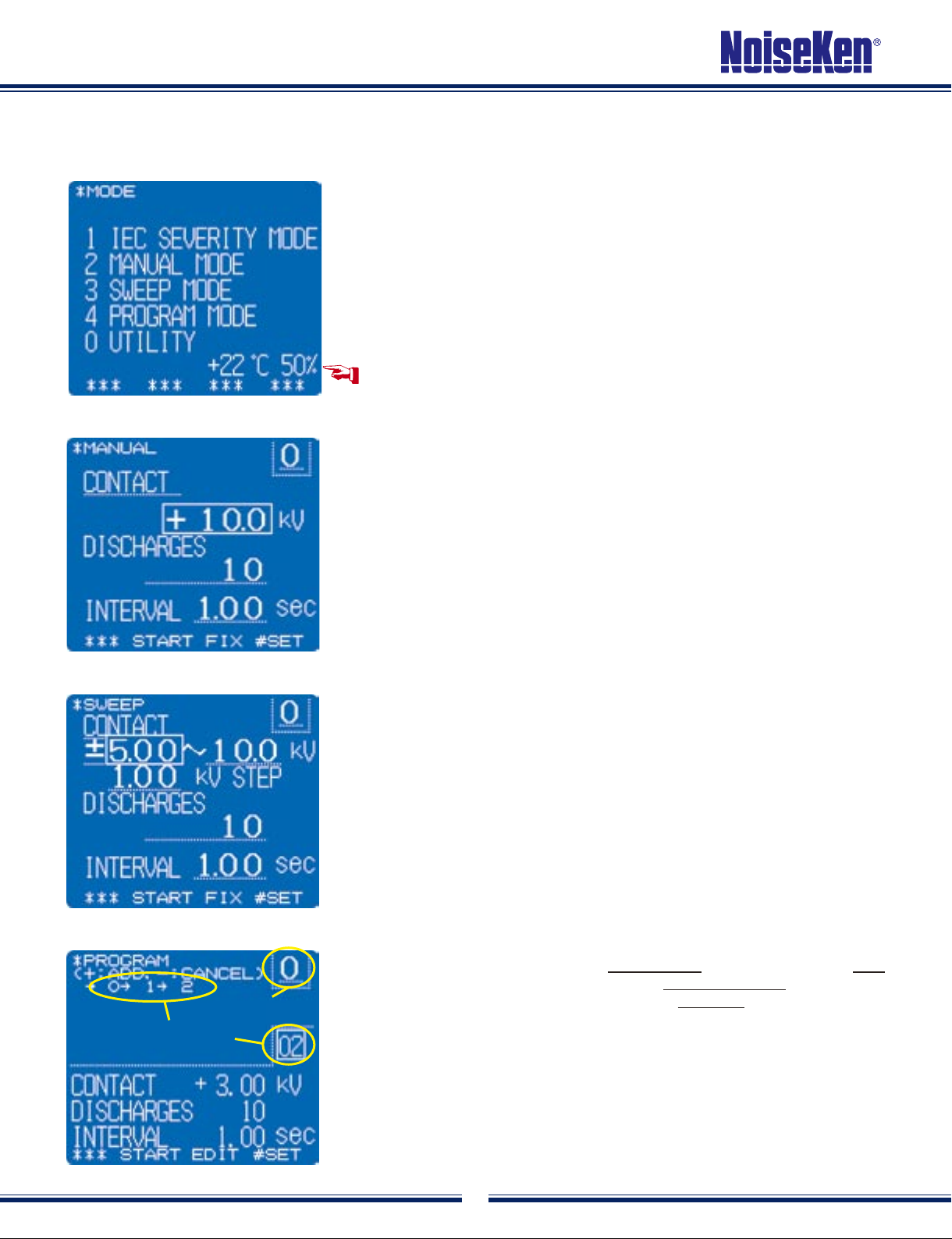
MENU DISPLAY
■
DISPLAY EXAMPLES
After pressing the main switch, press the mode button. This places the simulator
in the initial menu, which displays the four operational modes and utility mode.
The optional temperature/humidity sensor shows the current measured values.
●
MANUAL MODE
If you desire to operate the unit in the manual mode, press the corresponding tenkey, 2. Items to be set by the operator will appear. Discharge method (contact/air
discharge), discharge voltage, number of discharges and interval can be set. The
item in the cursor can be varied by using the ten-key or rotary knob.
Contact discharges:
For contact discharge testing, after completion of
required settings, press the START button and pull the trigger. The simulator will
then generate the required number of pulses at the required interval. Pulling the
trigger again will pause the unit. Pulling again will restart the unit .
Air discharges:
For air discharge testing, after completion of setting, press the
START key. To carry out air discharges,
keep pulling the trigger and approach the discharge tip to the EUT. Keep pulling
the trigger to maintain the HV relay in the on status.
●
SWEEP MODE
In this mode, the simulator generates discharges in an automatic ramp. Starting,
ending and step voltages can be freely set. In this mode, the number of
discharges set is that in each step. For example, when the simulator is set to
5kV for start voltage, 10kV for end voltage, 1kV for step voltage, in a way of 10
discharges at an interval of 1 second, it produces 10 pulses at 5kV at an interval
of 1 second and proceeds to 6kV pulses, also 10 discharges. These steps
continue until the simulator has completed 10 pulses of 10kV.
Two different ways of pulling the trigger:
When the trigger is pulled and
then released quickly, the simulator operates in a way that it pauses before it
proceeds to next step voltage. For continuous operation, pull the trigger for more
than 2 seconds. The message of "CONTINUOUS" is indicated on the upper right
side of the screen.
●
PROGRAM MODE
Test settings can be stored for 100 program units. Any combination of units
selected from those 100 units can consist of one test sequence, the longest is
up to 30 units. Here we call one test sequence a program. 50 programs can be
stored.
For program unit setting, press EDIT button. Settings of voltage, etc. can be
done in the same way as the other operation modes. The trigger functions in the
same ways as in the sweep mode. When pulled once and released instantly, the
simulator operation pauses before it goes to the next program unit. If pulled for
more than 2 seconds, the simulator operates continuously.
Program unit No.
Program No.
 Loading...