


Agilent
4-Port PNA-L Microwave
Network Analyzer
N5230A
300 kHz to 13.5, 20 GHz
Data Sheet
Please note: This document does not contain Agilent’s most up-to-date PNA-L network analyzer portfolio. This document is available for reference only for customers using Agilent’s legacy network analyzers. To view the current Agilent 4-port PNA-L Microwave Network Analyzer Data Sheet click here.
Note:
Specification information in this document is also available within the PNA-L network analyzer’s internal Help system.
Table of Contents
Definitions . . . . . . . . . . . . . . . . . . . . . . . . . . . . . . . . . . . . . . . . . . . . . . . . . . . . . . 3
Corrected System Performance . . . . . . . . . . . . . . . . . . . . . . . . . . . . . . . . . . . . . 4
Table 1. System dynamic range . . . . . . . . . . . . . . . . . . . . . . . . . . . . . . . . . . . . . . . . . . 4 Table 2. Extended dynamic range. . . . . . . . . . . . . . . . . . . . . . . . . . . . . . . . . . . . . . . . . 5 N5230A Option 140/145/146/240/245/246
Corrected system performance with 3.5mm connectors . . . . . . . . . . . . . . . . . . . . 6 Table 3. 85052B Calibration kit N5230A
Option 140/145/146/240/245/246. . . . . . . . . . . . . . . . . . . . . . . . . . . . . . . . . . . . . .6 Table 4. N4433A Electronic calibration module N5230A
Option 140/145/146/240/245/246. . . . . . . . . . . . . . . . . . . . . . . . . . . . . . . . . . . . . 8 Table 5. Uncorrected system performance . . . . . . . . . . . . . . . . . . . . . . . . . . . . . . . . 10 Table 6. Test port output . . . . . . . . . . . . . . . . . . . . . . . . . . . . . . . . . . . . . . . . . . . . . . . 11 Table 7: Test port input . . . . . . . . . . . . . . . . . . . . . . . . . . . . . . . . . . . . . . . . . . . . . . . . 13 Table 8. Dynamic accuracy . . . . . . . . . . . . . . . . . . . . . . . . . . . . . . . . . . . . . . . . . . . . . .16 Table 9. Test port input (group delay) . . . . . . . . . . . . . . . . . . . . . . . . . . . . . . . . . . . . 22
General Information. . . . . . . . . . . . . . . . . . . . . . . . . . . . . . . . . . . . . . . . . . . . . . 23
Table 10. Miscellaneous information . . . . . . . . . . . . . . . . . . . . . . . . . . . . . . . . . . . . . 23 Table 11. Front panel information. . . . . . . . . . . . . . . . . . . . . . . . . . . . . . . . . . . . . . . . 23 Table 12. Rear panel information . . . . . . . . . . . . . . . . . . . . . . . . . . . . . . . . . . . . . . . . 24 Table 13. Analyzer environment and dimensions . . . . . . . . . . . . . . . . . . . . . . . . . . . 25
Measurement Throughput Summary . . . . . . . . . . . . . . . . . . . . . . . . . . . . . . . . 26
Table 14. Typical cycle time (ms) for measurement completion . . . . . . . . . . . . . . . .26 Table 15. Cycle time vs IF bandwidth. . . . . . . . . . . . . . . . . . . . . . . . . . . . . . . . . . . . . .27 Table 16. Cycle time vs number of points . . . . . . . . . . . . . . . . . . . . . . . . . . . . . . . . . .28 Table 17. Data transfer time (ms). . . . . . . . . . . . . . . . . . . . . . . . . . . . . . . . . . . . . . . . .28
Specifications: Front-Panel Jumpers. . . . . . . . . . . . . . . . . . . . . . . . . . . . . . . . 29
Table 18: Measurement receiver inputs, 0.1 dB typical compression. . . . . . . . . . . 29 Table 19: Reference receiver input at max. specified output power . . . . . . . . . . . . 29 Table 20: Reference output at max. specified output power . . . . . . . . . . . . . . . . . . 29 Table 21: Source outputs at max. specified output power. . . . . . . . . . . . . . . . . . . . 30 Table 22: Coupler inputs, insertion loss of coupler thru. . . . . . . . . . . . . . . . . . . . . . 30 Table 23: Coupler outputs . . . . . . . . . . . . . . . . . . . . . . . . . . . . . . . . . . . . . . . . . . . . . . 30
Test Set Block Diagrams . . . . . . . . . . . . . . . . . . . . . . . . . . . . . . . . . . . . . . . . . . 31
N5230A Option 140 or 240
(standard test set and standard power range) network analyzer . . . . . . . . . . . . 31 N5230A Option 145 or 245
(configurable test set and extended power range) network analyzer . . . . . . . . . . . 31 N5230A Option 146 or 246
(configurable test set, extended power range, and internal second
source) network analyzer. . . . . . . . . . . . . . . . . . . . . . . . . . . . . . . . . . . . . . . . . . . . . 31
Web Resources . . . . . . . . . . . . . . . . . . . . . . . . . . . . . . . . . . . . . . . . . . . . . . . . . 32
2
This is a subset of technical specifications for the N5230A Options 140, 145, 146, 240, 245, and 246 network analyzers.
•Option 140, 300 kHz to 13.5 GHz, 4-port with standard test set and standard power range
•Option 145, 300 kHz to 13.5 GHz, 4-port with configurable test set and extended power range
•Option 146, 300 kHz to 13.5 GHz, 4-port with configurable test set and extended power range with internal second source
•Option 240, 300 kHz to 20 GHz, 4-port with standard test set and standard power range
•Option 245, 300 kHz to 20 GHz, 4-port with configurable test set and extended power range
•Option 246, 300 kHz to 20 GHz, 4-port with configurable test set and extended power range with internal second source
To view or print the N5230A technical specifications, visit our web site at www.agilent.com/find/pnal
This N5230A document provides technical specifications for the following calibration kit and ECal module only: 85052B and N4433A. Please download our free Uncertainty Calculator from www.agilent.com/find/na_calculator to generate the curves for your calibration kit and PNA setup.
Definitions
All specifications and characteristics apply over a 25 °C ±5 °C range
(unless otherwise stated) and 90 minutes after the instrument has been turned on.
Specification (spec.): Warranted performance. Specifications include
guardbands to account for the expected statistical performance distribution, measurement uncertainties, and changes in performance due to
environmental conditions.
Characteristic (char.): A performance parameter that the product is expected
to meet before it leaves the factory, but that is not verified in the field and is not covered by the product warranty. A characteristic includes the same guardbands as a specification.
Typical (typ.): Expected performance of an average unit which does not include guardbands. It is not covered by the product warranty.
Nominal (nom.): A general, descriptive term that does not imply a level of performance. It is not covered by the product warranty.
Calibration: The process of measuring known standards to characterize a network analyzer's systematic (repeatable) errors.
Corrected (residual): Indicates performance after error correction (calibration). It is determined by the quality of calibration standards and how well "known" they are, plus system repeatability, stability, and noise.
Uncorrected (raw): Indicates instrument performance without error correction. The uncorrected performance affects the stability of a calibration.
Standard: When referring to the analyzer, this includes no options unless noted otherwise.
3
Corrected System Performance
The specifications in this section apply for measurements made with the N5230A Options 140, 145, 146, 240, 245, and 246 analyzers with the following conditions:
•10 Hz IF bandwidth
•No averaging applied to data
•Isolation calibration with an averaging factor of 8
Table 1. System dynamic range at test port1
Standard configuration and standard power range (Options 140, 240)
Description |
Specification (dB) |
Typical (dB) |
|
at test port |
at test port |
||
|
|||
300 kHz to 10 MHz2 |
|
111 |
|
10 MHz to 4 GHz2 |
120 |
128 |
|
4 to 6 GHz |
118 |
129 |
|
6 to 10.5 GHz |
115 |
127 |
|
10.5 to 13.5 GHz |
107 |
119 |
|
13.5 to 15 GHz |
107 |
119 |
|
15 to 20 GHz |
103 |
116 |
Configurable test set and extended power range (Options 145, 245) Configurable test set, extended power range, and internal second source (Options 146, 246)
Description |
Specification (dB) |
|
Typical (dB) |
|
|||
at test port |
|
at test port |
|
|
|
||
300 kHz to 10 MHz2 |
|
|
111 |
10 MHz to 4 GHz2 |
120 |
|
128 |
4 to 6 GHz |
118 |
|
128 |
6 to 10.5 GHz |
113 |
|
125 |
10.5 to 13.5 GHz |
105 |
|
117 |
13.5 to 15 GHz |
105 |
|
11 |
15 to 20 GHz |
98 |
|
115 |
1.The system dynamic range is calculated as the difference between the noise floor and the specified source maximum output power. The effective dynamic range must take measurement uncertainties and interfering signals into account.
2.May be degraded by 10 dB at particular frequencies (multiples of 5 MHz) below 500 MHz due to spurious receiver residuals. Methods are available to regain the full dynamic range.
4
Table 2. Extended dynamic range1
Configurable test set and extended power range (Options 145, 245) Configurable test set, extended power range, and internal second source (Options 146, 246)
|
Specification (dB) at |
Typical (dB) at |
Description |
direct receiver |
direct receiver |
|
access input |
access input |
300 kHz to 10 MHz2 |
|
124 |
10 MHz to 4 GHz2 |
136 |
|
4 to 6 GHz |
134 |
|
6 to 10.5 GHz |
129 |
|
10.5 to 13.5 GHz |
121 |
|
13.5 to 15 GHz |
121 |
|
15 to 20 GHz |
114 |
|
1.The direct receiver access input extended dynamic range is calculated as the difference between the direct receiver access input noise floor and the source maximum output power. The effective dynamic range must take measurement uncertainties and interfering signals into account. This setup should only be used when the receiver input will never exceed its compression or damage level. When the analyzer is in segment sweep mode, it can have predefined frequency segments which will output a higher power level when the extended dynamic range is required (i.e. devices with high insertion loss), and reduced power when receiver compression or damage may
occur (i.e. devices with low insertion loss). The extended range is only available in one-path transmission measurements.
2.May be degraded by 10 dB at particular frequencies (multiples of 5 MHz) below 500 MHz due to spurious receiver residuals. Methods are available to regain the full dynamic range.
5

N5230A Option 140/145/146/240/245/246 Corrected system performance with 3.5 mm connectors1
Note: For any Sii reflection measurement:
Sjj = 0
For any Sij transmission measurement:
Sji = Sij when Sij ≤ 1
Sji = 1/Sij when Sij ≥ 1
Skk = 0 for all k
Table 3. 85052B Calibration kit
N5230A
•Option 140 or 240 standard test set and standard power range
•Option 145 or 245 configurable test set and extended power range
•Option 146 or 246 configurable test set and extended power range with internal second source
Applies to the N5230A Option 140/145/146/240/245/246 analyzers, 85052B (3.5mm) calibration kit, 85131F flexible test port cable set, and a full 4-port calibration. Also applies to the following condition: Environmental temperature 23° ±3 °C, with < 1 °C deviation from calibration temperature.
|
|
|
Specification (dB) |
|
||
Description |
10 to |
500 MHz to |
2 to |
8 to |
13.5 to |
|
500 MHz |
2 GHz |
8 GHz |
13.5 GHz |
20 GHz |
||
|
||||||
Directivity |
48 |
48 |
44 |
44 |
44 |
|
Source match |
40 |
40 |
33 |
31 |
31 |
|
Load match |
48 |
48 |
44 |
44 |
44 |
|
Reflection |
±0.003 |
±0.003 |
±0.003 |
±0.006 |
±0.006 |
|
tracking |
(+0.01/°C) |
(+0.01/°C) |
(+0.02/°C) |
(+0.03/°C) |
(+0.03/°C) |
|
Transmission |
±0.017 |
±0.017 |
±0.062 |
±0.125 |
±0.125 |
|
tracking |
(+0.01/°C) |
(+0.01/°C) |
(+0.02/°C) |
(+0.03/°C) |
(+0.03/°C) |
|
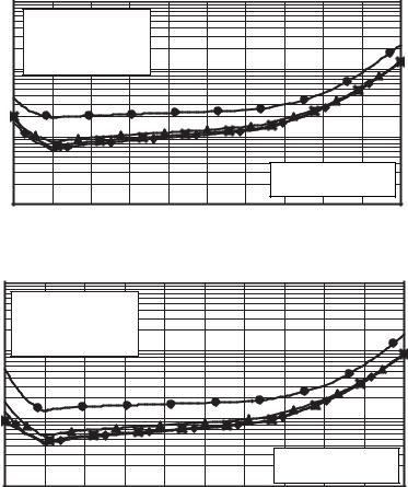
Transmission uncertainty (specifications)
Magnitude |
N5230A Option 140/145/146/240/245/246 with 85052B |
|
|
10 |
|
|
■ 10 to 500 MHz |
|
|
|
|
|
|
♦ 500 MHz to 2 GHz |
(dB) |
|
▲ 2 to 8 GHz |
1 |
● 8 to 20 GHz |
|
|
|
|
Uncertainty |
0.1 |
|
|
|
|
|
|
S11 = S22 = 0 |
Source power = -5 dBm
0.01
10 |
0 |
-10 |
-20 |
-30 |
-40 |
-50 |
-60 |
-70 |
-80 |
-90 |
Transmission coefficient (dB)
1.From 300 kHz to 10 MHz, performance is characterized as “typical”. To generate these typical values, please download our free Uncertainty Calculator from www.agilent.com/find/na_calculator.
6

Table 3. 85052B Calibration kit (continued) N5230A
• Option 140 or 240 standard test set and standard power range
• Option 145 or 245 configurable test set and extended power range
• Option 146 or 246 configurable test set and extended power range with internal second source
Phase
|
100 |
|
N5230A Option 140/145/146/240/245/246 with 85052B |
|
|
||||||
|
|
|
|
|
|
|
|
|
|
|
|
|
|
■ 10 to 500 MHz |
|
|
|
|
|
|
|
||
(degrees) |
|
♦ 500 MHz to 2 GHz |
|
|
|
|
|
|
|
||
10 |
▲ 2 to 8 GHz |
|
|
|
|
|
|
|
|
||
● 8 to 20 GHz |
|
|
|
|
|
|
|
|
|||
|
|
|
|
|
|
|
|
|
|
|
|
Uncertainty |
1 |
|
|
|
|
|
|
|
|
|
|
|
|
|
|
|
|
|
S11 = S22 = 0 |
|
|
||
|
|
|
|
|
|
|
|
|
|
||
|
0.1 |
|
|
|
|
|
|
Source power = -5 dBm |
|
||
|
|
|
|
|
|
|
|
|
|
|
|
|
10 |
0 |
-10 |
-20 |
-30 |
-40 |
-50 |
-60 |
-70 |
-80 |
-90 |
Transmission coefficient (dB)
Reflection uncertainty (specifications)
Magnitude |
N5230A Option 140/145/146/240/245/246 with 85052B |
|
||||
|
0.05 |
|
||||
|
■ 10 to 500 MHz |
|
|
|
|
|
|
|
|
|
|
|
|
(linear) |
0.04 |
♦ 500 MHz to 2 GHz |
|
|
|
|
▲ 2 to 8 GHz |
|
|
|
|
||
|
|
|
|
|
||
0.03 |
● 8 to 20 GHz |
|
|
|
|
|
Uncertainty |
S21 = S12 = 0 |
|
|
|
|
|
|
|
|
|
|
||
0.02 |
Source power = -5 dBm |
|
|
|
|
|
|
|
|
|
|
||
|
|
|
|
|
|
|
|
0.01 |
|
|
|
|
|
|
0 |
|
|
|
|
|
|
0 |
0.2 |
0.4 |
0.6 |
0.8 |
1 |
|
|
Reflection coefficient (linear) |
|
|
||
Phase |
N5230A Option 140/145/146/240/245/246 with 85052B |
|
||||
|
10 |
|
||||
|
|
|
|
|
|
|
|
|
|
|
|
■ 10 to 500 MHz |
|
(deg) |
8 |
|
|
|
♦ 500 MHz to 2 GHz |
|
|
|
|
▲ 2 to 8 GHz |
|
||
|
|
|
|
|
||
6 |
|
|
|
● 8 to 20 GHz |
|
|
Uncertainty |
|
|
|
S21 = S12 = 0 |
|
|
|
|
|
|
|
||
4 |
|
|
|
Source power = -5 dBm |
|
|
|
|
|
|
|
||
2 |
|
|
|
|
|
|
|
|
|
|
|
|
|
|
0 |
|
|
|
|
|
|
0 |
0.2 |
0.4 |
0.6 |
0.8 |
1 |
|
|
|
Reflection coefficient (linear) |
|
|
|
7
N5230A Option 140/145/146/240/245/246
Corrected system performance with 3.5 mm connectors1 (continued)
Table 4. N4433A Electronic calibration module
N5230A
•Option 140 or 240 standard test set and standard power range
•Option 145 or 245 configurable test set and extended power range
•Option 146 or 246 configurable test set and extended power range with internal second source
Applies to the N5230A Option 140/145/146/240/245/246 analyzers, N4433A
electronic calibration module, 85131F flexible test port cable set, and a full 4-port calibration. Also applies to the following condition:
Environmental temperature 23° ±3 °C, with < 1 °C deviation from calibration temperature.
|
|
|
|
Specification (dB) |
|
|
|
Description |
10 to |
500 MHz to |
2 to |
8 to |
13.5 to |
||
500 MHz |
2 GHz |
8 GHz |
13.5 GHz |
20 GHz |
|||
|
|||||||
Directivity |
52 |
|
52 |
47 |
45 |
45 |
|
Source match |
42 |
|
42 |
39 |
31 |
31 |
|
Load match |
45 |
|
45 |
41 |
35 |
35 |
|
Reflection |
±0.060 |
±0.060 |
±0.090 |
±0.040 |
±0.180 |
||
tracking |
(+0.01/°C) |
(+0.01/°C) |
(+0.02/°C) |
(+0.03/°C) |
(+0.03/°C) |
||
Transmission |
±0.045 |
±0.039 |
±0.055 |
±0.127 |
±0.160 |
||
tracking |
(+0.01/°C) |
(+0.01/°C) |
(+0.02/°C) |
(+0.03/°C) |
(+0.03/°C) |
||
Transmission uncertainty (specifications)
Magnitude |
||
|
10 |
N5230A Option 140/145/146/240/245/246 full 2-port2 cal using N4433A |
|
|
|
|
|
■ 10 to 500 MHz |
|
|
♦ 500 MHz to 2 GHz |
(dB) |
|
▲ 2 to 8 GHz |
1 |
● 8 to 20 GHz |
|
Uncertainty |
0.1 |
|
|
|
S11 = S22 = 0 |
Source power = -5 dBm
0.01
10 |
0 |
-10 |
-20 |
-30 |
-40 |
-50 |
-60 |
-70 |
-80 |
-90 |
Transmission coefficient (dB)
Phase
N5230A Option 140/145/146/240/245/246 full 2-port2 cal using N4433A
|
100 |
|
|
|
■ 10 to 500 MHz |
(degrees) |
|
♦ 500 MHz to 2 GHz |
|
▲ 2 to 8 GHz |
|
10 |
● 8 to 20 GHz |
|
|
|
|
Uncertainty |
1 |
|
|
S11 = S22 = 0 |
|
|
|
Source power = -5 dBm
0.1
10 |
0 |
-10 |
-20 |
-30 |
-40 |
-50 |
-60 |
-70 |
-80 |
-90 |
Transmission coefficient (dB)
1. From 300 kHz to 10 MHz, performance is characterized as “typical”. To generate these typical values, 8 please download our free Uncertainty Calculator from www.agilent.com/find/na_calculator.
2. All of the curves are for 2-port calibrations. Multiport uncertainties are currently not supported.
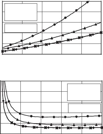
Table 4. N4433A Electronic calibration module (continued)
N5230A
•Option 140 or 240 standard test set and standard power range
•Option 145 or 245 configurable test set and extended power range
•Option 146 or 246 configurable test set and extended power range with internal second source
Reflection uncertainty (specifications)
Magnitude |
N5230A Option 140/145/146/240/245/246 with N4433A |
|
||||
|
0.05 |
|
||||
|
|
|
|
|
|
|
|
|
■ 10 to 500 MHz |
|
|
|
|
|
0.04 |
♦ 500 MHz to 2 GHz |
|
|
|
|
|
▲ 2 to 8 GHz |
|
|
|
|
|
(linear) |
|
|
|
|
|
|
0.03 |
● 8 to 20 GHz |
|
|
|
|
|
S21 = S12 = 0 |
|
|
|
|
||
|
|
|
|
|
||
Uncertainty |
0.02 |
Source power = -5 dBm |
|
|
|
|
|
|
|
|
|
||
0.01 |
|
|
|
|
|
|
|
|
|
|
|
|
|
|
0 |
|
|
|
|
|
|
0 |
0.2 |
0.4 |
0.6 |
0.8 |
1 |
|
|
Reflection coefficient (linear) |
|
|
||
Phase |
N5230A Option 140/145/146/240/245/246 with N4433A |
|
||||
|
10 |
|
||||
|
|
|
|
|
|
|
|
|
|
|
|
■ 10 to 500 MHz |
|
|
8 |
|
|
|
♦ 500 MHz to 2 GHz |
|
|
|
|
|
|
▲ 2 to 8 GHz |
|
(deg) |
6 |
|
|
|
● 8 to 20 GHz |
|
|
|
|
S21 = S12 = 0 |
|
||
|
|
|
|
|
||
Uncertainty |
|
|
|
|
|
|
4 |
|
|
|
Source power = -5 dBm |
|
|
|
|
|
|
|
||
2 |
|
|
|
|
|
|
|
0 |
|
|
|
|
|
|
0 |
0.2 |
0.4 |
0.6 |
0.8 |
1 |
|
|
|
Reflection coefficient (linear) |
|
|
|
9
Table 5. Uncorrected system performance1 |
|
||
Directivity |
Specifications |
Typicals |
|
Options 140, 145, 146, |
Options 140, 145, 146, |
||
|
|||
|
240, 245, 246 |
240, 245,246 |
|
300 kHz to 10 MHz |
|
–23 dB |
|
10 MHz to 1 GHz |
–28 dB |
|
|
1 to 3 GHz |
–25 dB |
|
|
3 to 5 GHz |
–20 dB |
|
|
5 to 11.5 GHz |
–17 dB |
|
|
11.5 to 13.5 GHz |
–15 dB |
|
|
13.5 to 20 GHz |
–15 dB |
|
|
Source match |
|
|
|
300 kHz to 10 MHz |
|
–8 dB |
|
10 MHz to 1 GHz |
–12 dB |
|
|
1 to 3 GHz |
–12 dB |
|
|
3 to 5 GHz |
–12 dB |
|
|
5 to 10.5 GHz |
–12 dB |
|
|
10.5 to 11.5 GHz |
–10 dB |
|
|
11.5 to 13.5 GHz |
–8 dB |
|
|
13.5 to 20 GHz |
–8 dB |
|
|
Load match |
|
|
|
300 kHz to 10 MHz |
|
–9 dB |
|
10 MHz to 1 GHz |
–20 dB |
|
|
1 to 3 GHz |
–20 dB |
|
|
3 to 5 GHz |
–18 dB |
|
|
5 to 11.5 GHz |
–12 dB |
|
|
11.5 to 13.5 GHz |
–7 dB |
|
|
13.5 to 16 GHz |
–7 dB |
|
|
16 to 20 GHz |
–7.5 dB |
|
|
Crosstalk2 |
|
|
|
300 kHz to 5 MHz |
|
–70 dB |
|
5 to 10 MHz |
|
–100 dB |
|
10 to 45 MHz |
|
–110 dB |
|
45 MHz to 4 GHz |
|
–122 dB |
|
4 to 6 GHz |
|
–123 dB |
|
6 to 10.5 GHz |
|
–120 dB |
|
10.5 to 13.5 GHz |
|
–115 dB |
|
13.5 to 15 GHz |
|
–115 dB |
|
15 to 20 GHz |
|
–110 dB |
|
1.Specifications apply over environmental temperature of 25 °C ±5 °C with less than 1 °C variation from calibration temperature.
2.Measurement conditions: normalized to a thru, measured with two shorts, 10 Hz IF bandwidth, averaging factor of 8, alternate mode source power set to the lesser of the maximum power out or the maximum receiver power.
10
 Loading...