


Aeroflex-3920B

For the very latest specifications visit www.aeroflex.com
Wireless
3920B Series Analog and Digital Radio Test Platform
Introducing the 3920B, the latest radio test solution
from Aeroflex for engineering, production and field
service applications. The 3920B features an
improvement to the RF signal generator phase
noise specification of -110 dBc/Hz at 10 kHz off-
set. The instrument provides a comprehen-
sive range of general purpose analog measure-
ment facilities as well as advanced digital test
options. The 3920B includes many standard
features as well as a host of optional test capabilities
and digital personalities.
The 3920B standard features include:
• 1 GHz frequency range
• High performance FM/AM/SSB analog duplex
test capabilities
• Sensitive receiver with built-in pre-amp for off
air measurements
• Color coded pass/fail results
• -140 dBm (typical) DANL spectrum analyzer
with 8 markers
• Dual-Channel oscilloscope to 4 MHz
• Full audio analysis for AF level, frequency,
SINAD and distortion measurements
• Three high accuracy audio modulators/function
generators
• Three high accuracy audio baseband generators
• Tone encode and decode functionality including
DTMF, DCS, tone remote, 2-tone sequential,
and 5/6-tone
• GPIB, Ethernet, USB and RS-232 interfaces
• HP/Agilent 8920B remote emulation
The 3920B also includes many optional features including:
• 2.7 GHz frequency range extension
• Harmonics and spurious measurements
• Tracking generator
• Audio spectrum analyzer and audio tracking generator (used for
analog simulcast alignment)
• IQ generator for use with IQCreator
®
• P25 conventional operation with advanced parametric/protocol
analysis
• P25 trunking operation
• LSM generate and receive analysis
• P25 Phase II TDMA physical layer transmitter and receiver
testing
• Off Air Monitor for P25 message logging – protocol analysis tool
• P25 AES encryption
• SmartZone
TM
and SMARTNET
TM
trunking
• DMR (MOTOTRBO
TM
) mobile and repeater tests
• TETRA mobile, base station and DMO tests
• HPD (High Performance Data) base and mobile simulation
• NXDN
TM
, dPMR and ARIB STD T98
Automatic test and alignment options include:
• Motorola ASTRO
®
, ASTRO
®
25 and APX™ Series radios
• EF Johnson ES Series radios
• BK DPHX5102X Series radios
• TIA/EIA-603 FM land mobile radio test software
• MOTOTRBO radios
• Harris P7300, P5500 and XG-75 Series
• Kenwood P25 TK-5X10, 5X20 and NXDN Series radios
• DMR Repeaters
Featuring Improved RF Signal
Generator Phase Noise
Performance
The one test set for all your narrowbanding test needs!
With the largest selection of digital radio options of any radio test set,
the 3920B will meet all of your narrowbanding test needs, both now and
in the future. The software defined digital architecture of the 3920B
provides for future technology enhancements as new digital
technology becomes available. You can easily perform software updates
in the field, making additions of new software features and options as
simple as plugging in a USB flash memory drive.
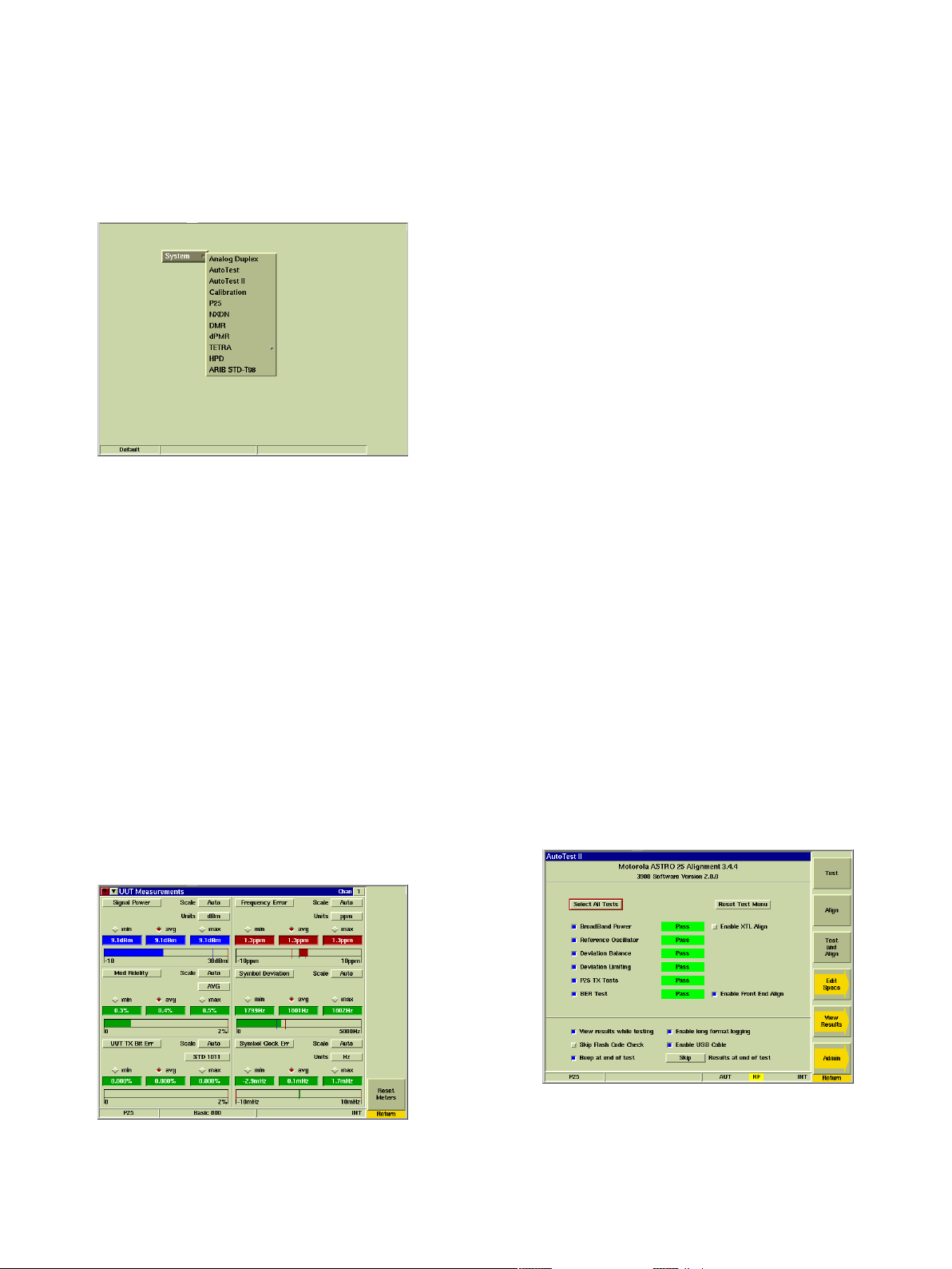
Menu of Radio Test Systems in the 3920B
Ease of Use
Combining the power of an onboard PC with a 30 GB hard-drive and
Linux OS, the 3920B can support USB mouse and keyboard interface
for very easy operation as well as almost unlimited save/recall setups,
saving time and effort. Multiple methods of controlling the 3920B
include the front panel keys, using a mouse and keyboard, or through
a VNC application on your PC, touch-screen tablet or mobile phone.
Ease of Test
To make you more productive, the 3920B is not only simple to use but
has features that makes testing a radio quick and repeatable. The 3920B
features easy-to-read meters with Pass/Fail color coding for instant
Go/NoGo testing. With these easy-to-configure meters, you can set up
unique Pass/Fail parameters for each radio type that you are testing.
When used with the save/recall locations, this allows for instant recall of
the test parameters, so semi-technical or non-technical individuals can
simply key the radio and test. The meters will display “Green” for good,
“Red” for high and “Blue” for low. A quick glance and the operator will
know that the radio is within established test parameters.
P25 UUT Measurements Tile Maximized, Showing Green, Red
and Blue Indications
High Performance
Measurement speed is directly related to processing power and
internal communications. The 3920B digital architecture utilizes a
mixture of powerful digital signal processors and programmable logic.
Coupled to the use of a compact PCI backplane capable of delivering
peak rates of >100 MB, this ensures that the instrument has the power
to acquire, synchronize and process data, producing measurement
results to the user with the minimum of delay.
Accurate Testing
Time Base: With a 0.01 ppm OCXO frequency standard, the 3920B
provides ultra-reliable RF frequency measurements. For even more
stability, the 3920B provides an external frequency reference input.
Generator: Level accuracy is important in determining today’s
receiver performance in design, manufacturing and field service
environments. With a 1 dB (0.6 dB typical) level accuracy on the RF
output ports, the 3920B provides consistent results in testing receiver
parameters.
Receiver: For sensitive measurement, e.g. off-air analysis, a low power
input is provided via the antenna input port. This low level input gives
the user the ability to measure an off the air signal as low as -100
dBm or -115 dBm with the internal pre-amp selected. Direct input of
signal power of up to 125 W is supported, making the 3920B
compatible with virtually all practical requirements for mobile
terminal and base station test.
Audio: With high accuracy audio generators from 1 mV to 8 V rms,
the 3920B provides level accuracy to ±1% of the setting. The audio
generator frequency ranges from 20 Hz to 40 kHz and 0.1 Hz resolution
provides solid audio performance for audio testing. The AF Counter
features full range from 20 Hz to 20 kHz.
Automatic Testing
The Auto-Test II environment provides you with the capability to turn
the 3920B into a stand alone ATE test environment. With the built-in
PC running your test script, or one of our available automatic test and
alignment applications, the 3920B can be conformed to your exact
testing needs. Available with the Auto-Test II option for the 3920B are
a selection of applications covering many of the latest digital radios.
With these applications, you can automatically test and align the
transmitter/receiver of a radio in as little as 5 minutes.
Motorola ASTRO 25 Radio Alignment
More automatic test and alignment options are being added all the
time. For the latest selection of scripts for the 3920B, go to www.aerof-
lex.com/3920 and click on the 3920 Radio Test Set Scripts link in the
Product Directory.
2
For the very latest specifications visit www.aeroflex.com
3920B STANDARD FEATURES
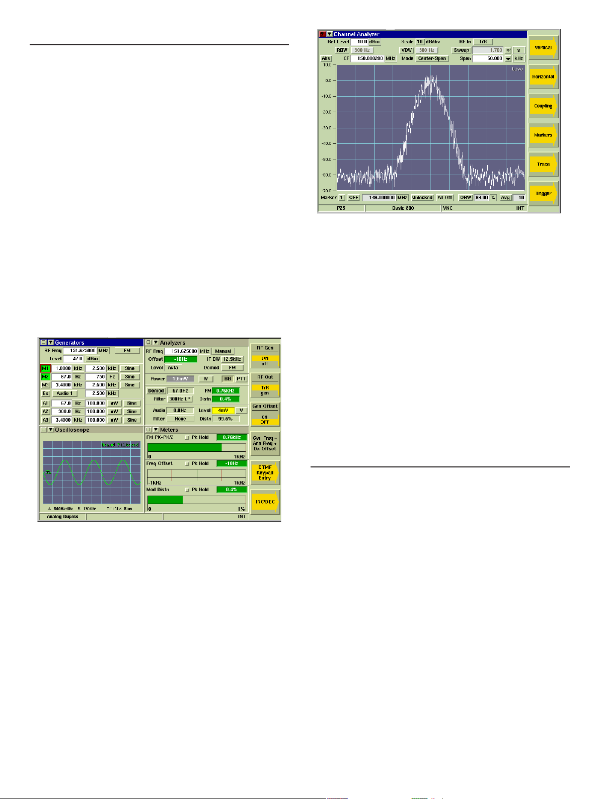
FM/AM/SSB Analog Duplex operation: The 3920B features advanced
RF testing capabilities for FM/AM/SSB radio transmitters and receiv-
ers. The features for analog duplex testing are:
• 1 GHz frequency range for transmitter and receiver (2.7 GHz
optional)
• Three Modulation sources
• Three Audio sources
• DTMF encode and decode
• DCS encode and decode
• 2-tone sequential and tone remote encode and decode
• Tone sequential encode operation that includes up to 40 tones, user
defined pause, tone frequency shift, all standard tone sequential
codes and two USER defined sequential codes
• Tone sequential decode that can decode according to standard tone
protocols or according to user defined tone protocol
• Channel analyzer that can simultaneous display the RF spectrum
while demodulating received signal
• Meters for measuring RF Power, Modulation, Frequency Offset,
Distortion, Audio level, SINAD, SNR, and Hum and Noise
• Dual Channel 4 MHz Oscilloscope
Analog Duplex Screen
Full span spectrum analyzer: View signals from 1 MHz to 1 GHz
with the 3920B or to a full 2.7 GHz with the frequency extended option.
With a DANL of -140 dBm (300 Hz RBW with pre-amp enabled), the
3920B provides high performance spectrum analysis. This full band
analyzer provides plenty of range to view harmonics and other
spurious emissions in and out of band.
Spectrum Analyzer
Digital Multimeter: Now standard for the 3920B is the Digital
Multimeter. The Digital Multimeter comes with three new ports on the
front panel used for measuring AC/DC volts, AC/DC amps and OHMS.
Remote Control: The 3920B supports remote control via GPIB for
automated test system control. A VXI pnp VISA driver allows easy test
system integration of the 3920B. In addition to a native 3920B command
set, the 3920B also supports commands for the HP/Agilent 8920B that
allows migration from the 8920B to the 3920B extremely easy.
Remote Operation: Use of the 3920B Ethernet connection permits
remote operation from anywhere in the world making it possible to
download new software or remotely interrogate instrument status. With
an internal VNC server, users can install VNC software on their PC or
Tablet PC and remotely operate the front panel of the 3920B from
virtually anywhere on the planet. All that is needed is the ability to
access the unit’s IP address.
OPTIONAL TEST CAPABILITIES
Site Monitoring Application (390XOPT051)
The 3920B brings impressive new capabilities to site monitoring
applications. With option 392XOPT051, the user now has the ability
to leave the 3920B on-site while the unit provides automated data
logging of the site’s effective receiver sensitivity. When connected
to a good documented receiver (a “golden” radio), the 3920B will
automatically calculate the Effective Receiver Sensitivity (ERS) at
a predetermined interval (example: every 10 seconds) over a speci-
fied time (example: log ERS for 72 hours). As these measurements
are taken, a min/average/max SINAD is displayed, and the data is
logged to the 3920B’s internal hard-drive. Spectral information is also
optionally logged with each measurement to help locate and track
sources of interference. This gives the system engineer a valuable tool
in determining site location performance and system RF boundaries.
IQ Gen Modulation (390XOPT054)
IQCreator is an Aeroflex developed PC based software utility that
gives the user the ability to develop their own waveforms to use as
the modulation source. Since the waveforms are defined by I and Q,
virtually any type of complex digital modulation format can be
created. With the IQ Gen Modulation option, once the IQ waveform
is created it can easily be uploaded to the 3920B and used as the
modulation source in the Analog Duplex System.
3
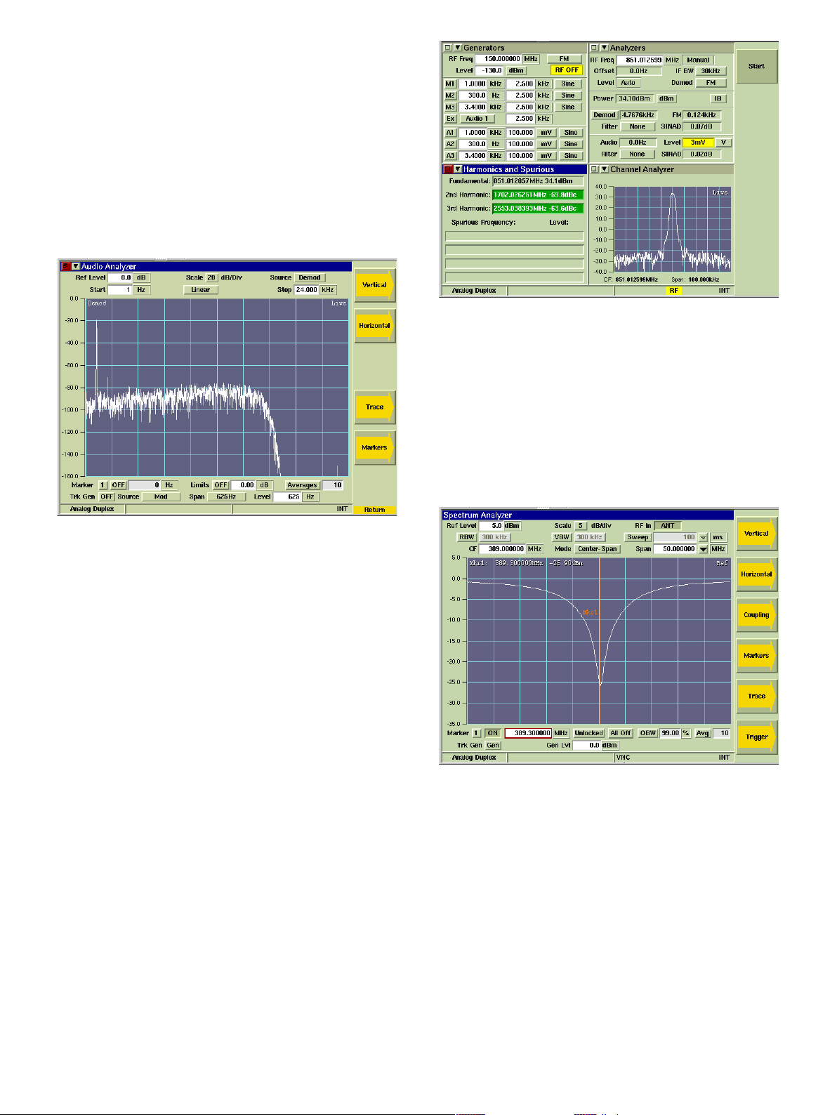
Audio Analyzer (390XOPT055)
With 390XOPT055, the 3920B provides audio spectral analysis of
the recovered audio signal, either from the audio inputs or from the
demodulated RF signal. This feature allows users to view frequency
amplitude in relation to other audio frequencies and to isolate
problems such as noise in audio circuits. With a frequency range of
1 Hz to 24 kHz, the audio analyzer covers more than the full audio
frequency range of mobiles and hand-helds. In addition, there are
two markers, plus a peak hold and average function. The user can
also capture traces that can be stored and then recalled later for
use as a comparison with a live trace. A tracking generator option
(390XOPT210) is also available as an add-on to the audio analyzer.
Audio Analyzer
2.7 GHz Frequency Range (392XOPT058)
The 3920B comes standard with a generate and receive frequency
range of 10 MHz (100 kHz usable) to 1.05 GHz. This option will
extend the range to 2.7 GHz.
Harmonics and Spurious (390XOPT060)
The ability to quickly and accurately measure the harmonics and
spurious of the transmitter of a radio is the function of 390XOPT060.
The fundamental frequency is automatically detected and meas-
ured and then the second and third harmonics are measured and
compared. In addition, the spurious signals that are higher than the
configured level are identified and displayed. The frequency and
level of the fundamental, as well as the harmonics and spurs, are then
displayed. This option makes finding the harmonics and spurious
transmitter very simple. Simply connect the transmitter of the radio
to the 3920B, key the radio and press Start.
Harmonics and Spurious
Tracking Generator (390XOPT061)
A full featured spectrum analyzer is available, standard, on all 3920Bs.
Available as an option to the spectrum analyzer, the 3920B tracking
generator allows the user to look at the response of a duplexer, fil-
ter bank or other RF device on the spectrum analyzer. This option
greatly simplifies the often laborious process of checking or changing
the tuning of a duplexer. When used with the optional return loss
bridge (AC4105), the spectrum analyzer/tracking generator can
measure the return loss of an antenna or cable.
Spectrum Analyzer with Tracking Generator
Power Between Markers (390XOPT064)
Also available as an option, the power between markers option
provides a measurement of the amount of power between the
spectrum analyzer markers. With this feature, the user can set the
position of two markers on the spectrum analyzer and then measure
the amount of power in the bandwidth selected with those markers.
This will enable the user to determine the amount of power in an
adjacent channel or in the center channel.
POCSAG (390XOPT067)
The user can now test and verify the operation of both POCSAG
transmitters and receivers. When this option is enabled, there are
two new tiles available from the tile drop down arrows. This adds the
following capability:
4
For the very latest specifications visit www.aeroflex.com
POCSAG Encode
• Send Alphanumeric or Numeric POCSAG formatted pages
• Select any rate from 400 to 4800 Hz
• Select deviation from 0 to 50,000 Hz
• Select Normal or Inverted for polarity
• Pick from a selection of canned messages or create a custom
message
• Select RIC (Radio Identification Code) of encoded message, or
send to a range of RIC’s
POCSAG Decode
• Select Decode Format - either Automatic, Alphanumeric or
Numeric
• Select Decode Filter - decode all messages or only messages to a
user selectable RIC
• Select Normal or Inverted Polarity for decoding
• Displays deviation and rate of decoded message
• Displays the RIC and the type bits (two bits) of the decoded
messages as well as the message
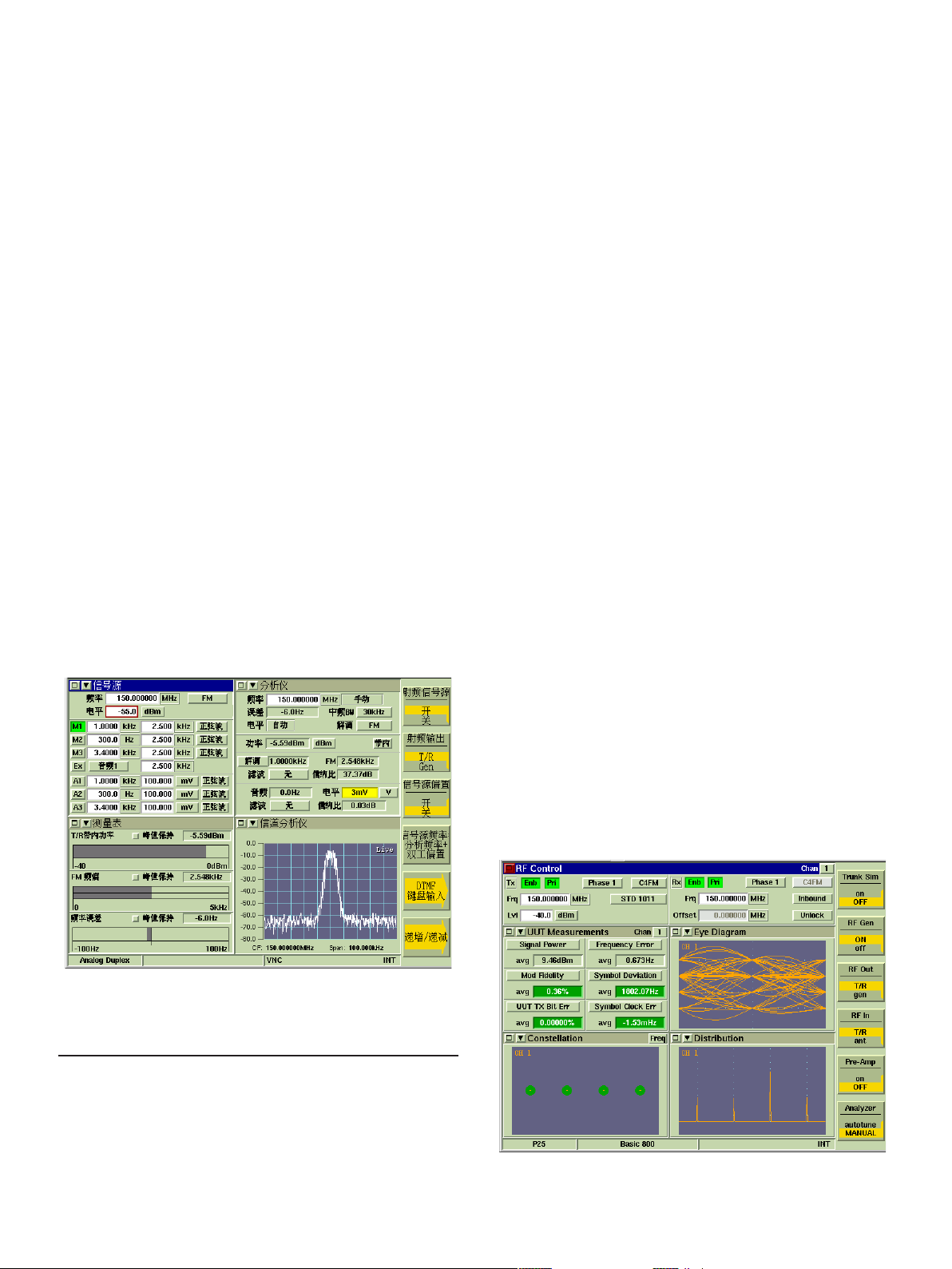
Chinese GUI (390XOPT090)
This option enables the selection of either Chinese or English as
the language for the graphical user interface for the Analog Duplex
system. When enabled, a selection is added to the utilities screen
that allows the user to choose between English or Chinese character
display in the audio Analog Duplex system.
Illustration of Chinese GUI
OPTIONAL SYSTEM PERSONALITIES
In addition to the Analog Duplex system, the 3920B can sup-
port a number of optional test systems or personalities, installed
concurrently. Personalities include:
• TETRA digital trunked radio systems for mobile station and base
station testing
• TETRA direct mode testing
• APCO P25 conventional and trunked radios
• APCO P25 Phase II TDMA
• SmartZone and SMARTNET
• DMR (Digital Mobile Radio)
• NXDN
• HPD (High Performance Data)
• dPMR (digital Private Mobile Radio)
• ARIB T98 (Digital Convenience Radio Equipment For Simplified
Service)
P25 CONVENTIONAL OPERATION (390XOPT200)
The 3920B P25 Conventional Option provides test features for test-
ing P25 radios and systems. Featured is the ability to transmit P25
C4FM standard waveforms and analyze P25 received waveforms. The
analysis of the received waveforms consists of the ability to perform
RF and modulation parametric tests. The vocoder enables the user
to perform transmit and receive audio testing. Included in this option
is the capability to:
• Measure C4FM modulation fidelity and symbol deviation
• Measure power, frequency error and TX BER
• Measure symbol clock error
• Measure RX BER
• Display eye diagram of C4FM demodulation
• Display constellation plot of C4FM symbols
• Display C4FM symbol deviation distribution plot
• Transmit full TIA/EIA-102 test patterns (STD1011, CAL,
SILENCE, STD511, etc.) as specified by TIA- EIA-102.CAAA-C
• Transmit and receive live audio using the vocoder
• Transmit stored speech patterns
• Decode voice channel header and link control messages
• Encode link control messages
• Perform DES encryption
P25 Conventional
5
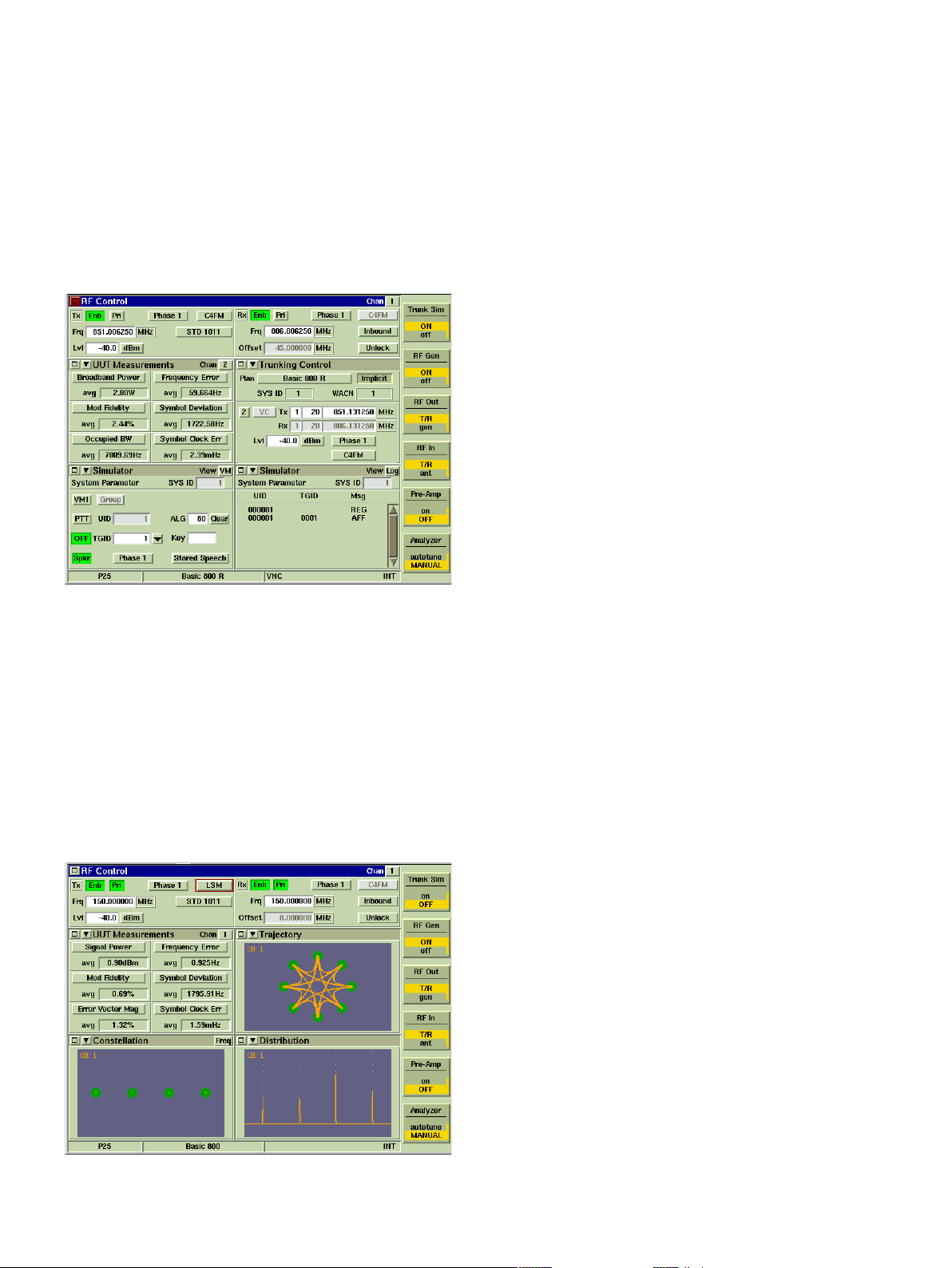
P25 Trunking Operation VHF/UHF/700/800 MHz
(390XOPT201)
To further enhance P25 operation, the addition of the P25 trunking
option allows simulation of a P25 control channel in any frequency
band. Channel plans may be configured to test virtually any P25
trunked system. A simulator tile logs the messages sent by the
radio under test and allows the 3920B to simulate a virtual mobile,
configured to talk to the radio under test. This option enables the
user to originate a group call to the radio under test or make a group
call from the radio under test to the 3920B. In addition, the user can
have multiple radios register and affiliate with the 3920B and then
originate calls from one radio to the other radios.
P25 Trunking Simulation
LSM Generate and Receive/Analysis (390XOPT204)
In addition to the standard P25 modulation, also available on the
3920B is the capability to generate and receive Linear Simulcast
Modulation (LSM). This option, available as an extension of P25 con-
ventional operation, enables measurements that are specific to LSM.
It also adds a graphical analysis of the demodulated LSM signal that is
normally only found in vector signal analyzers. Since LSM is a
complex type modulation, this plot shows the inphase versus
quadrature phase (I versus Q) of the demodulated LSM signal. In
addition, this option adds Error Vector Magnitude to the selection of
measurements available from the UUT Measurements tile.
LSM Signal Analysis Screen
P25 Control Channel Logger Option (390XOPT206)
This option provides the user a tool to perform advanced protocol
analysis on both control channel and voice channel data. With this
option the user can log P25 data by streaming the received data in real
time from the Ethernet port to a PC. This data is logged in an XML
format so that the user can easily view the data using a text editor or
use an external program to perform further analysis on the data. This
data can be logged at three different levels ranging from the raw data
symbols up through decoded data. The data is time-stamped on a
frame by frame basis. In addition to being able to log data, the user
can also send data to the 3920B to be transmitted, making the 3920B
into a completely user defined data modem for P25.
SmartZone and SMARTNET (390XOPT207)
This option provides support for Motorola Astro SmartZone and
SMARTNET systems, including support for rebanded channels in
the 800 MHz band.
KVL Keyloader Option (390XOPT209)
This option provides an interface to the KVL Keyloader enabling
the user to be able to directly enter keys into the 3920B using a
KVL-3000+.
Analog Simulcast Option (390XOPT210)
This option is actually an extension to the Audio Analyzer option
and acts as a tracking generator for the audio analyzer. This feature
is designed primarily for use in characterizing the performance of
Motorola Analog Simulcast systems and enables detailed alignment
of the 0-100 Hz band. In addition, this option allows for extended
characterization of audio circuits from 0-10 kHz.
Explicit Mode Trunking (390XOPT212)
The advanced form of frequency channel assignment known as
Explicit Messaging is supported by adding option 390XOPT212 to
the P25 Trunking Operation VHF/UHF/700/800 MHz option. The
explicit mode of operation assigns the actual channel/frequency over
the air by providing the exact TX and RX frequency assignments
directly to the radio.
Unit to Unit Call (390XOPT213)
This option adds capability of testing the unit to unit call functionality
of a mobile station to the P25 trunking option. The user can either
originate a unit to unit call from the mobile station or from the test
set.
Adjacent Channel Broadcast Message (390XOPT214)
This option adds the adjacent status broadcast message to the
control channel messages transmitted by the 3920B. This will
enable the user to test the capability of the mobile station to operate
correctly in the presence of this message. The purpose of this
message is to inform mobile stations of the presence and status of
sites adjacent to this particular site.
Secondary Control Channel Broadcast Message
(390XOPT215)
This option adds the secondary control channel broadcast message
to the control channel messages transmitted by the 3920B. This will
enable the user to test the capability of the mobile station to operate
correctly in the presence of this message. This message is used to
inform mobile stations of other control channels or other potential
backup control channels at this site.
6
For the very latest specifications visit www.aeroflex.com
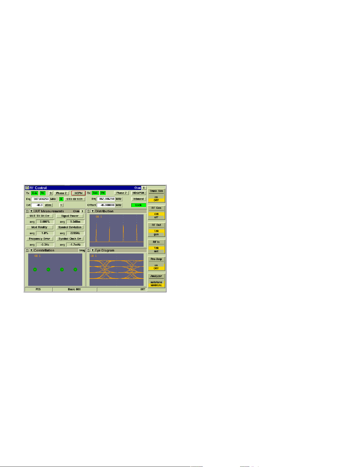
P25 Phase II Two-Slot TDMA (Time Division Multiple Access)
Physical Layer (390XOPT220)
One of the newest features of the 3920B is the capability to test P25
Phase II TDMA operation of both base stations and mobile stations.
With this option, the 3920B can measure and analyze the different
modulations used for both the outbound and inbound signals used
in P25 Phase II. With the modulation for Phase II being completely
different from the Phase 1 C4FM modulation; this option is critical
for radio technicians, designers, or anyone involved with the roll-out
of P25 Phase II systems. Included with this option are the following
features:
• H-CPM (inbound modulation) modulation and demodulation
• H-CPM eye diagram, distribution plot, and constellation
• H-DQPSK (outbound modulation) modulation and
demodulation
• H-DQPSK eye diagram, distribution plot, and constellation
• Generation of all H-CPM standard patterns
• Generation of all H-DQPSK standard patterns
• UUT measurements for Phase II including modulation fidelity,
symbol deviation, symbol clock error, frequency error, power
and TX Bit Error
P25 Phase II
Off Air Monitor Software for P25 Message Logging -
Protocol Analysis Tool (390XOPT230)
The Aeroflex 3920B P25 Off Air Monitor (OAM) is used to
capture and view APCO P25 messages sent over the air. The OAM
can receive and demodulate P25 RF signaling, decode P25 messa-
ges and log these messages to a file for later viewing. Both trunked
(control and traffic) and conventional channels are supported,
allowing network engineers to:
• Verify compliance to P25 standards
• Troubleshoot existing P25 systems
• Analyze third party signaling
This option is a PC application that, using the data from option
390XOPT206, performs an advanced decoded display and log of the
XML data streams from multiple P25 channels. This provides the
user with the data to perform a complete analysis of all channels of a
P25 trunked system.
P25 AES Encryption (390XOPT240)
With the addition of this option, the 3920B supports P25 encryp-
tion formats and manual key entry for systems that employ DES
OFB Type III (included in 390XOPT200) or AES encryption
(390XOPT240). These options allow decoding of encrypted voice
frames to verify encrypted channel performance. Encryption keys
may be loaded manually using either the front panel or external
keypad or with option 390XOPT209, keys may be loaded with the
Project 25 Key Fill Device (KFD) interface protocol. Additionally,
keys may be loaded using KVL ASN mode of operation found in KVL-
3000 and older model key loaders from Motorola.
X2-TDMA Test Suite (390XOPT219)
Available for testing X2-TDMA test systems, this option is available
through Motorola only.
X2-TDMA Mobile Emulator (390XOPT245)
This option enables the testing of X2-TDMA base stations. This
option is available through Motorola only.
P25 Performance Test Triggers (390XOPT260)
In order to perform the P25 Performance Tests required by the TIA
102-CAAA standard, the 3920B has the capability with this option of
generating trigger signals. This Sync I/O port on the rear panel of
the 3920B is used to source this trigger. The output trigger signal is
generated when any of the following occur.
• Switching between the STD SILENCE pattern and the STD 1011
pattern
• Switching between the STD BUSY pattern and the STD 1DLE
pattern
• Enabling the STD LDU1 pattern
• Enabling the STD LDU2 pattern
• During trunking simulation at each slot boundary
• During trunking simulation, when a Channel Grant message is
transmitted
X2-TDMA Advance Test Suite (390XOPT261)
This option combines 390XOPT216 and 390XOPT245.
MOTOROLA HPD TESTING OPTION (390XOPT300)
• Generate/receive HPD signals
• Modulation - 64QAM, 16QAM and QPSK (inbound and
outbound)
• Transmitter parameters including signal power, frequency error,
EVM
• Symbol clock error, RX BER, burst timing error and occupied
bandwidth
• I & Q modulation analysis including constellation and trajectory
plots of the data symbols, synch and pilot bits
• Display of Min/Max and average as specified by the number of
bursts
• Pass/Fail indication using color code meters
Aeroflex has developed this test mode for Motorola to address the
need for testing their high performance packet data operation on
7

both mobiles and base stations in the 700 and 800 MHz bands. HPD
systems operate within the normal 25 kHz mobile radio bandwidth.
The 3920B HPD options provide users with the ability to test High
Performance Data systems. HPD can be configured for two modes
of operation. When configured to operate in BR Mode the test set
simulates base radio operation and is used to test the functionality of
Motorola HPD Mobile Subscriber Units (MSU). When configured
to operate in MSU Mode the test set simulates Mobile Subscriber
Unit operation and is used to test the functionality of Motorola Base
Repeaters (BR).
Example of HPD Tiles
Motorola HPD Advanced Analysis Package (390XOPT301)
More advanced features are available with 390XOPT301 including:
• Received Data Stream Logger. Logs the data portion of the
HPD signal and displays it in hex.
• RX Time Display. Shows frequency error, power and symbol
clock error over time.
• HPD Magnitude/Phase Estimation. Displays magnitude and
phase fluctuations of the received signal.
• Eye Diagram and I/Q over time displays
• Power Profile. Shows the power over time and in a burst
(TDMA transmission).
• Power Ramps. Shows the power up and power down portion of
the TDMA burst.
Motorola HPD Testing Suite (390XOPT302)
This option combines 390XOPT300 and 390XOPT301.
DMR (390XOPT400)
Add advanced testing capability for DMR (Digital Mobile Radio)
with 390XOPT400. This option enables the Aeroflex 3920B Digital
Radio Test Set to test and align a wide range of DMR repeaters
and mobile stations. DMR radio technology is a digital radio format
offering advanced communications features specified by the ETSI
technical standard ETSI TS 102-361-1. Capabilities of the 3920B
include:
• Generate and receive DMR modulated signals
• Measure FSK error and magnitude error
• Measure symbol deviation
• Measure symbol clock error
• Measure slot power
• Distribution plot of symbol deviation
• Eye diagram of FSK demodulation
• Power profile of burst and of burst ramp up/ramp down
• Transmit and receive live audio using the vocoder
• Transmit stored speech patterns
• Test duplex or simplex mobiles
• Wake-up burst for testing repeaters
• Synchronize with repeaters
• BER testing
• Encode color code and call ID
• Decode color code, unit ID and call ID
Example of DMR Tiles
DMR XML Channel Logger Option (390XOPT402)
With this option, the user can now capture and log to a file (on a
PC connected to the 3920B through a LAN) the raw data that is
transmitted by a mobile station or repeater. The data is formatted
using XML, so that it can be decoded with an external program
(developed by the user) or viewed with a text editor. This is perfect
for the engineer doing development work or the test engineer in the
field that needs to capture the data being transmitted by a repeater
or subscriber unit. The data is captured by connecting a PC to the
3920B through an Ethernet crossover cable. Using the PC appli-
cation, (available at www.aeroflex.com/3920) “DMR XML channel
logger for 3920”, the user can both log DMR XML data and send
XML files that can control the data being transmitted by the 3920B.
dPMR (390XOPT420)
dPMR is an ETSI standard specified in ETSI TS 102 658. This
option adds advanced testing capabilities that conform to the
requirements of this ETSI standard. The transmitter tests include
power, frequency error, FSK error, symbol deviation and symbol
clock error. This option also provides several graphical screens that
provide more insight into the accuracy of the dPMR modulation.
NXDN (390XOPT440)
Add advanced testing capability for NXDN with 390XOPT440.
This option enables the Aeroflex 3920B Digital Radio Test Set to
perform a variety of Transmitter and Receiver tests on any NXDN
radio. Transmitter measurements include:
• Signal power
8
 Loading...