


Your products may have passed the test standards, but can they survive in the real world?
There are many ESD standards for your equipment.
Do those standards really represent the real world phenomenon?
Reconsider your testing program to assure that your products are really ESD-immune.
Consider NoiseKen's ESS series ESD simulators to ensure your products survival in the real world.
The issue of product-level ESD (electrostatic discharge) immunity has been attracting continued interest because it is an important quality factor in equipment reliability, durability and sometime safety.
Generally, among the causes of equipment malfunction, problems caused by ESD are the most difficult events against which to incorporate protective measures, since the causal relation generally cannot be found easily. This often
makes ESD test programs extensive, complex, burdensome and time-consuming. Thanks to the following benefits, NoiseKen's ESS series ESD simulators are your best choice whatever your requirements are for design, qualification, production or diagnostic tests.
●Meet and far exceed the requirements in EN/IEC61000-4-2 and ISO10605
●Up to 30kV output in both contact and air discharges
●A light weight discharge gun
●Easily changeable capacitor and resistor units
●A wide range of options
●CE marked
Two models ESS-2002EX and ESS-2000AX are available.The above-mentioned capabilities are common to them.
The ESS-2002EX is the basic model with a built-in discharge counter and time controller.
The ESS-2000AX is the fully programmable menu-driven simulator enabling users to carry out tests in more automated manner.

Electrostatic Discharge Simulator
ESD Simulator
ESS-2000AX & TC-815R Conforming to IEC61000-4-2
■FEATURES
•Fully programmable menu-driven simulator providing three operation modes: IEC standard, Manual and Sequence
•A 5.7-inch color LCD for easy setting and good visibility
•Unique shape for the operator's easy access to the controls and displays even when the unit is put on the floor level (ground plane)
•Communications with PC through the optic serial interface
•A wide variety of the dedicated options
ESS-2000AX & TC-815R (with PS-806 gun stand)
■CONTROLS INDICATORS AND TERMINALS
LCD panel: displays the settings of various test parameters
Polarity select key: selects the desired polarity
Increment and decrement keys: change the value for the selected parameter
Radiation level select key:
provides the selection of NORMAL or EXTRA in terms of the strength of radiation from the discharge gun. The EXTRA mode reduces the radiation. In the EXRA mode, faster than 1.0s setting for discharge interval is not accepted.
 Discharge mode key: selects either Air or Contact discharge
 TRIG key: starts the test. This key works when the unit is set to ESS (main unit) trigger.
 STOP key: turns off the HV circuitry
START key: turns on the HV circuitry
Warning lamp: alight while the HV is on and blinks while discharges are in progress
Contrast adjustment: rotating the knob adjusts the contrast of the LCD screen
Function keys: the relevant active functions or parameters are shown in the display
<Front Panel>
AUX connector: interface with auxiliary devices such as Automatic ESD Eliminator (option), Warning Lamp (option), external trigger and interlock circuits. Optional AUX connector junction box enables two or three devices to be used simultaneously.
REMOTE connector: communicates with the user's PC through this optic RS232C interface
AC input
<Rear Panel>
1
Electrostatic Discharge Simulator
ESS-2000AX
■DISPLAY EXAMPLE
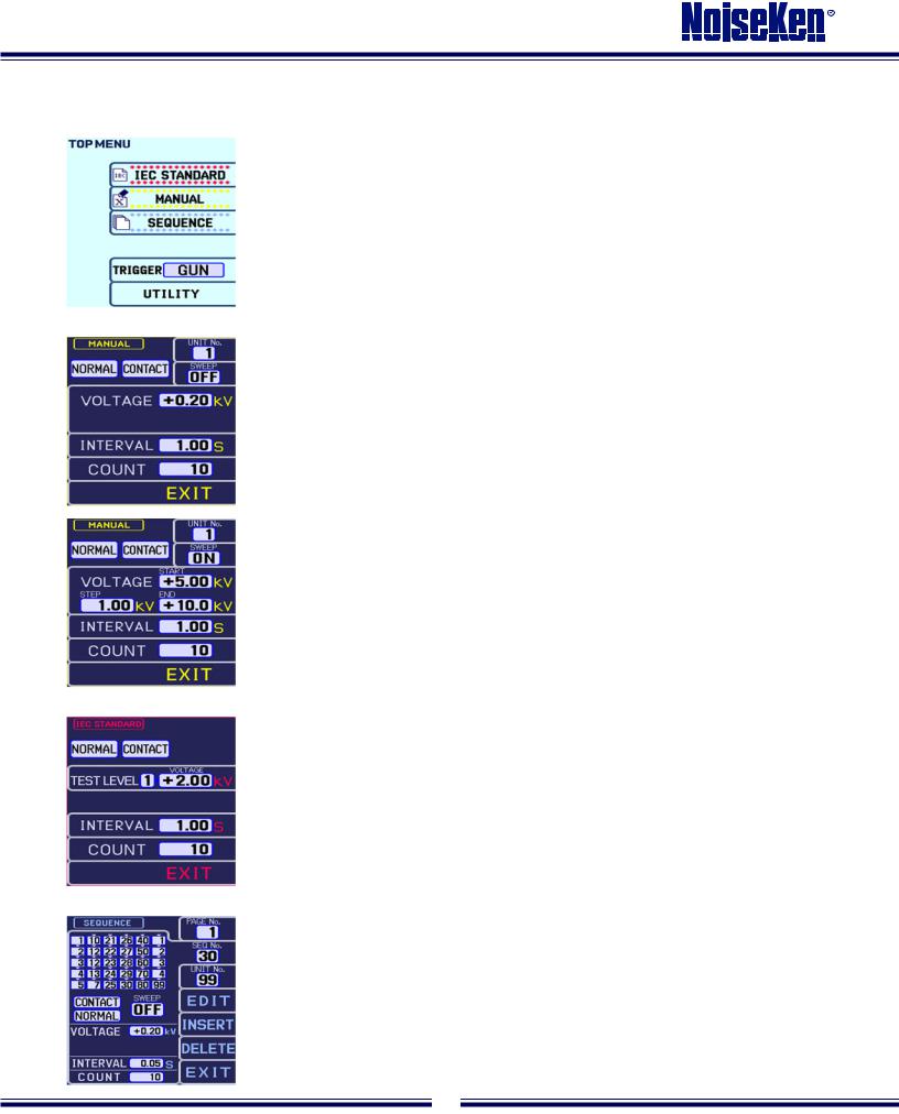
•Top Menu
After pressing the main switch, press the EXIT key. This places the simulator in the initial menu, which displays three operational modes, trigger selection and utility.
•Manual Mode
If you desire to operate the unit in the manual mode, press the corresponding function key. The parameters to be set by the operator will appear. Discharge method (contact/air discharge), discharge voltage, number of discharges and interval can be set. Select the parameter by pressing the corresponding function key then the value can be altered by the Increment or Decrement key.
Contact discharges: For contact discharge testing, after completion of required settings, press the START button and pull the trigger. The simulator will then generate the required number of pulses at the required interval. Pulling the trigger again will pause the unit. Pulling again will restart the unit.
Air discharges: For air discharge testing, after completion of setting, press the START key. To carry out air discharges, pull and hold the trigger to maintain the HV relay in the on status and approach the discharge tip to the EUT.
When the SWEEP function is active, the simulator generates discharges in an automatic voltage ramp. The initial, final and step voltages can be freely set. In this mode, the number of discharges set is that in each step. For example, when the simulator is set to 5kV for the initial voltage, 10kV for final voltage and 1kV for step voltage, in a way of 10 discharges at an interval of 1 second, it produces 10 pulses at 5kV at an interval of 1 second and proceeds to 6kV pulses, also 10 discharges. These steps continue until the simulator has completed 10 pulses of 10kV.
Two different ways of pulling the trigger: When the trigger is pulled and then released quickly, the simulator operates in a way that it pauses before it proceeds to next step voltage. For continuous operation, pull the trigger for more than 2 seconds. A sign of "CONTINUE" is indicated on the screen and the simulator runs a complete step ramp test without further operator’s trigger.
•IEC Standard Mode
The four test levels are preset. Select the desired level and run a test.
•Sequence Mode
The simulator can store up to 99 tests including Sweep settings. Each test is given a number (called Unit No). Any combination of units selected from 99 tests in the Manual Mode can consist of one test sequence having 30 units maximum. Twenty test sequences can be stored. For a unit setting, press EDIT button. Settings of voltage, etc. can be done in the same way as in the Manual mode.
2
 Loading...