


Agilent 4284A/4285A
Precision LCR Meter Family
20 Hz to 1 MHz
75 kHz to 30 MHz
Technical Overview

Agilent
precision LCR meter family
Utilize state-of-the art measurement technologies
•6-digits of resolution at any range
•Basic accuracies of 0.05% (Agilent 4284A) and 0.1% (Agilent 4285A)
•20 impedance parameters to access and measure
•Constant V or I test signal level
•20 Vrms test signal level (Agilent 4284A)
Move your process toward error-free operation
•Instrument setup state storage
•Comparator functions
•Selectable frequency error corrections
•Open, short and load corrections remove parasitics
1.Refer to specifications for complete accuracy.
2.Supplimental information only.
Key specifications
Agilent 4284A precision LCR meter
Test frequency |
20 Hz to 1 MHz over 8610 selectable frequencies |
|
|
Measurement range1 |
|
|
|Z|, R, X :0.01 mΩ to 99.9999 MΩ |
|
|Y|, G,B :0.01 nS to 99.9999 S |
|
C :0.01 fF to 9.99999 F |
|
L :0.01 nH to 99.9999 kH |
|
D :0.000001 to 9.99999 |
|
Q :0.01 to 99999.9 |
|
|
Basic accuracy |
|Z| , C and L:0.05% D:0.0005 |
|
|
Test signal level range |
|
Voltage |
5 mVrms to 2 Vrms |
Current |
50 µArms to 20 mArms |
|
|
Constant test signal level range |
|
Voltage |
10 mVrms to 1 Vrms |
Current |
100 µArms to 10 mArms |
|
|
Measurement time 2 |
39 ms/190 ms/830 ms at 1 kHz |
|
|
4284A with Option 4284A-001
Test signal level range |
|
Voltage |
5 mVrms to 20 Vrms |
Current |
50 µArms to 200 mArms |
|
|
Constant test signal level range |
|
Voltage |
10 mVrms to 10 Vrms |
Current |
100 µArms to 100 mArms |
|
|
Internal DC bias |
± (1 mV ~ 40 V), ≤ 100 mA, 0.1% accuracy |
|
|
4284A with Option 4284A-002 and 42841A
DC current bias |
0.01 A to 20 A (with 42841A and 42842A) |
|
0.02 A to 40 A (with 42841A x 2 ea., 42842B and 42843A) |
|
|
2

Satisfying your performance needs
Adapt instrument configurations to fit your test needs
•Internal voltage biasing up to ±40 Vdc3
•High current biasing up to 40 A dc3 (Agilent 4284A)
•Wide range of frequencies, 20 Hz to 30 MHz
•BIN’ing and comparator functions for handlers
•SMD, axial and radial test fixtures3
Simplify your system development and integration
•Programming language compatible with IEEE 488.2
•Test port extensions: maximum 4 m for 4284A3 and 2 m for 4285A
•Identical operation for the entire family of products
•Scanner, handler and GPIB interfaces3
1.Refer to specifications for complete accuracy.
2.Supplimental information only.
3.The options, the accessories, or the test fixtures are needed.
Key specifications
Agilent 4285A precision LCR meter
Test frequency |
75 kHz to 30 MHz with 100 Hz resolution |
|
|
Measurement range1 |
|
|
|Z|, R, X :0.01 m Ω to 99.9999 MΩ |
|
|Y|, G,B :0.01 nS to 99.9999 S |
|
C :0.01 fF to 999.999 µF |
|
L :0.001 nH to 99.9999 H |
|
D :0.000001 to 9.99999 |
|
Q :0.01 to 99999.9 |
|
|
Basic accuracy |
|Z|, C and L:0.1% D:0.001 |
|
|
Test signal level range |
|
Voltage |
5 mVrms to 2 Vrms |
Current |
200 µArms to 20 mArms |
|
|
Constant test signal level range |
|
Voltage |
10 mVrms to 1 Vrms |
Current |
100 µArms to 20 mArms |
|
|
Measurement time2 |
30 ms/65 ms/200 ms |
4285A with Option 4285A-001
Internal DC bias ± (1 mV ~ 40 V), ≤ 100 mA, 0.1% accuracy
4285A with Option 4285A-002, 42841A, and 42842C
DC current bias 0.01 A to 10 A
3

Versatile component measurements
Characterize inductive devices
•Sweep high current conditions
•Identify device properties precisely
•Test to RF frequencies
Low frequency measurements: Agilent 4284A
Inductive devices can now be accurately characterized from 20 Hz to 1 MHz with a dc bias current up to 40 A1 dc.
High frequency measurements: Agilent 4285A
The Agilent 4285A’s wide 75 kHz to 30 MHz range allow you to test RF inductors with improved accuracy and 0.001 nH resolution. Magnetic heads, ferrite-cores, and power inductors that need to be tested at a specified current signal level can be easily tested with the Agilent 4285A.
Precise ceramic capacitor measurements
•Test at 1 kHz and 1 MHz
•Resolve measurements to low values
•Maintain constant signal levels
1 kHz and 1 MHz are the primary testing frequencies for ceramic materials and capacitors. The Agilent 4284A can provide these test frequencies while maintaining an equally excellent accuracy and 6-digits of measurement resolution.
1 MHz accuracies of capacitance (0.05%) and dissipation factor (0.0005) are essential for characterizing DUTs with low dissipation factors. Dissipation factors can change as a function of the applied test signal level to the DUT. For reliable and consistent measurements, the Agilent 4284A can maintain a constant voltage test signal level.
1. Need Option 4284A-001
Inductance rolloff due to high dc current bias
Dissipation factor rise due to high ac signal
4

Adaptable parameter testing
Discover new material properties
•High accuracy and precise measurements
•Wide frequency ranges
•High test signal levels
•Agilent 16451B dielectric test fixture
The Agilent precision LCR meter family provides the accuracy, resolution, high test signal and bias levels1 required for material measurements. Using the Agilent 16451B dielectric test fixture provides you with accurate permittivity and dissipation factor measurements.
The ability to output a constant test signal level permits repeatable and accurate magnetic/dielectric measurements. Both the Agilent 4284A and Agilent 4285A offer variable voltage and current test signal level control.
Semiconductor testing
•Extend the test cable to the DUT
•Detect small parameter changes
•Rapidly acquire data
•Test at multiple frequencies
Both instruments allow you to extend the front panel measurement port through test cables, switches, and probers directly to the DUT. The 6-digits of resolution give you the ability to sense and identify changes not normally seen by conventional LCR meters.
The accuracies of the Agilent 4284A at key test frequencies up to 1 MHz permit complete DUT evaluation for either production or laboratory needs.
For high speed device testing at frequencies above 1 MHz, the best solution is the Agilent 4285A.
1. Need Option 4284A/4285A-001
A material’s characteristics versus frequency
C-V characteristics sample—MOS diode
5

One LCR meter family
for your product’s life cycle
Research and development
Research tomorrow’s electronic components now
•Increase measurement confidence
The basic accuracies are:
Agilent 4284A 0.05% and Agilent 4285A 0.1%.
•Detect 1 ppm changes
The 6-digits of resolution permit you to measure differences in materials not detectable before.
•Fit the instrument to your test needs
For low frequency applications the Agilent 4284A is the ideal tool. For testing at RF frequencies the Agilent 4285A is the best solution.
Material design
Design and test new materials
•Material test fixtures
For accurate permittivity and dissipation factor measurements of solid dielectric materials, the 16451B dielectric test fixture is provided. The 16452A liquid test fixture is provided for the permittivity measurements of liquids with minimal conductivity.
•Sample program
By using the sample program in the operation manual of 16451B, complex permittivity can be calculated rather easily and instantly. In addition, with the use of a spreadsheet soft ware, the frequency response of permittivity can be displayed in a graph.
1.For 4284A, need Option 4284A-006
2.Choose the combination from Option 4284A/4285A-201, 4284A/4285A-202, or 4284A/4285A-301
3.Need Option 4284A/4285A-301
Production test
Reduce production test factors
•Increase test throughput
The precision LCR meter family reduces testing costs by providing accurate high throughput testing.
•Interface easily to handlers
Built-in comparator, cable compensation1, and interfaces2 permit system integration.
•Minimize operator error
Instrument state storage minimizes costly setup errors.
Quality assurance
Automated quality assurance
•Reduce your system development time
The Agilent 4284A and Agilent 4285A are designed to be used as elements in systems. This means GPIB, programming, and the ability to interface with scanners3.
•Painlessly integrate the system
GPIB and a scanner3 interface allow the instruments to easily integrate into system configurations.
•Leverage your programming experience
Learning to program one instrument automatically means you learn both.
6

Comprehensive incoming inspection
Satisfying difficulties and requirements of impedance measurements during incoming inspection
Many types of measurements requiring a variety of measurement conditions have to be carried out during incoming inspection. However, as measurement instruments cannot perform all of the measurements required, substitute measurements are made. On the other hand, purchasing all the necessary equipment would substantially increase capital costs.
By employing the precision LCR meter family, a wide frequency range is covered (20 Hz to 1 MHz for 4284A and 75 kHz to
30 MHz for 4285A) and various test signal levels can be set (20 Vrms/200 mArms for 4284A Option 4284A-001 and
2 Vrms/20 mArms for 4285A). In addition, the ALC function allows measurements of constant-voltage and constant-current signals, and the added capability of Option 4284A/4285A-001 enables up to ±40 V of dc bias to be applied to the DUT. As a result of these features, a variety of measurement conditions can be carried out.
Furthermore, the precision LCR meter family achieves high accuracy measurements (basic |Z| measurement accuracy: 0.05% for 4284A and 0.1% for 4285A), permitting the characteristics of inductors and capacitors to be evaluated with excellent reliability. Also, built-in compensation functions reduce the influence of test fixtures to a minimum, further raising the reliability.
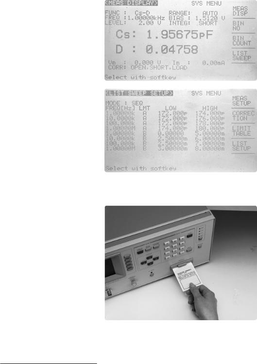
Built-in functionalities
for efficient measurements
In order to save time and facilitate the efficiency of measurement routines, the precision LCR meter family has the following features. The memory card1 allows the measurement conditions to be preset for various components with different measurement needs. The comparator function can be set to sort into a maximum of 10 BINs, enabling many components to be handled during inspection. The Option 4284A/4285A-301 scanner interface solves the problem of having discrepancies in measurement values for different channels of the switching matrix by allowing channel compensation for up to 128 channels.
1. Need Option 4284A/4285A-004
7
User friendly Interface
Simple front panel operation
•Clearly view the display
•See all instrument settings
•Interactive softkeys for simple control
Directly view all instrument settings and measurement results on the large LCD display. This simplifies operation and improves operator efficiency by minimizing readout error.
The softkeys simplify front panel operation by allowing the user to easily change instrument states by moving the LCD cursor with cursor keys. The softkeys
will automatically change to reflect the cursor’s position. This minimizes the number of menus and key strokes.
Customized test frequencies
Non-volatile memory
•Eliminate costly setup errors
•Increase user productivity
•Archive tests
The instruments contain two types of user accessible memory; internal and external (memory cards)1. The memory can easily be used to store measurement setups. Later, a setup can be loaded back into the instrument. This reduces test setup errors and increases the user’s productivity.
The memory can store 10 different instrument states, complete with correction data and system configuration. Entire
setups including limit information can
now be stored and loaded using either Inserting the memory card1 the internal memory or the memory card1.
The memory card1 system is completely electronic and is based on EEPROM.
1. Need Option 4284A/4285A-004
8
Testing with the proper tools
Measure the components’ performance in your power supply
•Test your components under load conditions
•Bias inductive devices with high currents
•Satisfy your needs with the right instrument
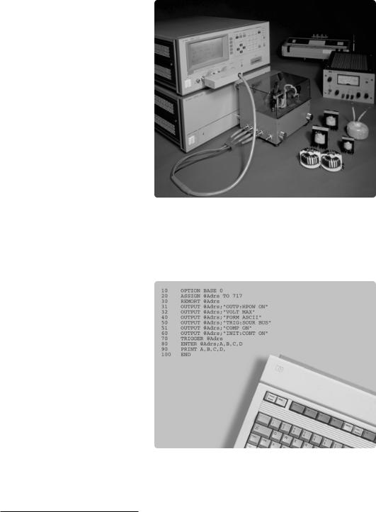
Designing advanced switching power supplies require the use of inductors and transformers that operate in the RF regions.
For low frequencies, the Agilent 4284A1 precision LCR meter with the
Agilent 42841A bias current source,
High current bias for inductor testing under load conditions
and the 42842A/B bias current test fixtures all combine to form a 40 A dc test system.
Where a high frequency measurement is required, use an Agilent 4285A2, an Agilent 42842C bias current test fixture,
and an Agilent 42841A bias current source to achieve up to 10 A dc biasing with measurements at 30 MHz.
Reduce system development time
The 4284A and 4285A employ a programming language, which is compatible with the IEEE 488.2. Since the command names are similar to the measurement functions, the time spent for creating and debugging programs can be largely minimized. The
operation manual lists several key sample
programs, allowing the user to efficiently Code generation made easy create a program for their measurement
system.
1.Need Option 4284A-002
2.Need Option 4285A-002
9
 Loading...