


Agilent-E4421B
Atec Agilent-E4421B, Agilent-E4424B, Agilent-E4432B, Agilent-E4433B, Agilent-E4435B User Manual
...
Agilent
ESG Family of RF Signal Generators
Data Sheet
Notice
This document is updated as often as once
a month. Please contact Agilent
Technologies for the latest information or
check the ESG Web site at
http://www.agilent.com/find/esg
Analog only Digital and analog
ESG-A series ESG-AP series ESG-D series ESG-DP series
(high spectral purity) (high spectral purity)
250 kHz – 1 GHz E4400B E4423B E4430B E4434B
250 kHz – 2 GHz E4420B E4424B E4431B E4435B
250 kHz – 3 GHz E4421B E4425B E4432B E4436B
250 kHz – 4 GHz E4422B E4426B E4433B E4437B

2
Table of contents
Introduction . . . . . . . . . . . . . . . . . . . . . . . . . . . . . . . . . . . . . . . . . . . . . . . . . . . . . . . . . . . . . . . . . . . . . . . . . . . . . . . . . . . . . . . . . . . .3
Specifications for analog and digital models . . . . . . . . . . . . . . . . . . . . . . . . . . . . . . . . . . . . . . . . . . . . . . . . . . . . . . . . . . . . . . . . .4
Characteristic SSB phase noise for ESG-AP and ESG-DP series . . . . . . . . . . . . . . . . . . . . . . . . . . . . . . . . . . . . . . . . . . . . . . . . .6
Specifications for digital models only . . . . . . . . . . . . . . . . . . . . . . . . . . . . . . . . . . . . . . . . . . . . . . . . . . . . . . . . . . . . . . . . . . . . . .10
I/Q baseband generator . . . . . . . . . . . . . . . . . . . . . . . . . . . . . . . . . . . . . . . . . . . . . . . . . . . . . . . . . . . . . . . . . . . . . . . . . . . . . . . . .11
Dual arbitrary waveform generator . . . . . . . . . . . . . . . . . . . . . . . . . . . . . . . . . . . . . . . . . . . . . . . . . . . . . . . . . . . . . . . . . . . . . . . .16
Multichannel, multicarrier CDMA personality . . . . . . . . . . . . . . . . . . . . . . . . . . . . . . . . . . . . . . . . . . . . . . . . . . . . . . . . . . . . . . .17
Bit Error Rate (BER) analyzer . . . . . . . . . . . . . . . . . . . . . . . . . . . . . . . . . . . . . . . . . . . . . . . . . . . . . . . . . . . . . . . . . . . . . . . . . . . . .18
GSM/EDGE base station Bit Error Rate Test (BERT) . . . . . . . . . . . . . . . . . . . . . . . . . . . . . . . . . . . . . . . . . . . . . . . . . . . . . . . . . .18
Baseband BER (Bit Error Rate) tester . . . . . . . . . . . . . . . . . . . . . . . . . . . . . . . . . . . . . . . . . . . . . . . . . . . . . . . . . . . . . . . . . . . . . .19
Multichannel 3GPP W-CDMA personality . . . . . . . . . . . . . . . . . . . . . . . . . . . . . . . . . . . . . . . . . . . . . . . . . . . . . . . . . . . . . . . . . .20
Multichannel cdma2000 personality . . . . . . . . . . . . . . . . . . . . . . . . . . . . . . . . . . . . . . . . . . . . . . . . . . . . . . . . . . . . . . . . . . . . . . .21
Real-time 3GPP W-CDMA personality . . . . . . . . . . . . . . . . . . . . . . . . . . . . . . . . . . . . . . . . . . . . . . . . . . . . . . . . . . . . . . . . . . . . .23
Real-time cdma2000 personality . . . . . . . . . . . . . . . . . . . . . . . . . . . . . . . . . . . . . . . . . . . . . . . . . . . . . . . . . . . . . . . . . . . . . . . . . .25
Real-time EDGE personality . . . . . . . . . . . . . . . . . . . . . . . . . . . . . . . . . . . . . . . . . . . . . . . . . . . . . . . . . . . . . . . . . . . . . . . . . . . . . .27
Alternate time slot power level control . . . . . . . . . . . . . . . . . . . . . . . . . . . . . . . . . . . . . . . . . . . . . . . . . . . . . . . . . . . . . . . . . . . .27
Improved ACP performance for TETRA, CDMA and W-CDMA . . . . . . . . . . . . . . . . . . . . . . . . . . . . . . . . . . . . . . . . . . . . . . . . .27
General characteristics . . . . . . . . . . . . . . . . . . . . . . . . . . . . . . . . . . . . . . . . . . . . . . . . . . . . . . . . . . . . . . . . . . . . . . . . . . . . . . . . . .28
Ordering information . . . . . . . . . . . . . . . . . . . . . . . . . . . . . . . . . . . . . . . . . . . . . . . . . . . . . . . . . . . . . . . . . . . . . . . . . . . . . . . . . . . .30
ESG family application and product information . . . . . . . . . . . . . . . . . . . . . . . . . . . . . . . . . . . . . . . . . . . . . . . . . . . . . . . . . . . . .31

3
Introduction
Standard Agilent Technologies ESG family RF signal generators
incorporate a broad array of capabilities for testing both analog
and digital communications systems. Adding flexible options
provides a test solution that will evaluate the performance of a
communication system to the requirements of nearly all current
and proposed air interface standards. Many test functions can
be customized to meet the needs of proprietary and other
nonstandard wireless protocols as well. You can configure
your instrument to address a wide variety of tests—from
altering nearly every aspect of a digital signal or signal operating
environment, to creating experimental signals. This flexibility,
along with an architecture that accepts future enhancements
makes the ESG family an excellent choice for wireless
communications system testing now and in the future.
ESG family of RF signal generators
The family consists of four series:
ESG-A series: analog instruments
E4400B, E4420B, E4421B, E4422B
ESG-AP series: analog instruments with high spectral purity
E4423B, E4424B, E4425B, E4426B
ESG-D series: digital and analog instruments
E4430B, E4431B, E4432B, E4433B
ESG-DP series: digital and analog instruments with high
spectral purity
E4434B, E4435B, E4436B, E4437B
Please refer to the related literature in the section
ESG family application and product information
for additional information.
Key standard features for entire family
• Expandable architecture
• Broad frequency coverage
• Choice of electronic or mechanical attenuator
• Superior level accuracy
• Wideband FM and ΦM
• Step sweep (frequency, power and list)
• Built-in function generator
• Lightweight, rack-mountable
• 3-year warranty
• 2-year calibration cycle
Standard features only in the digital series
• Broadband analog I/Q inputs
• I/Q adjustment capabilities and internal calibration
• Excellent modulation accuracy and stability
• Coherent carrier output
Options available only with the digital series
• Built-in dual arbitrary waveform generator
• Multichannel, multicarrier CDMA personality
• Multichannel W-CDMA 1.0 personality
• Multichannel cdma2000 personality
• Real-time 3GPP W-CDMA personality
• Real-time cdma2000 personality
• Real-time EDGE personality
• Internal bit-error-rate analyzer
• Versatile timeslot, data and burst generation
• Adjustable symbol rates, filter factors and
burst shape
• Digital modulation formats for DECT, GSM, NADC,
PDC, PHS, and TETRA
Options available only with the analog series
• High-performance pulse modulation
4
Frequency
Range
ESG-A series
E4400B 250 kHz to 1 GHz
E4420B 250 kHz to 2 GHz
E4421B 250 kHz to 3 GHz
E4422B 250 kHz to 4 GHz
ESG-AP series
E4423B 250 kHz to 1 GHz
E4424B 250 kHz to 2 GHz
E4425B 250 kHz to 3 GHz
E4426B 250 kHz to 4 GHz
ESG-D series
E4430B 250 kHz to 1 GHz
E4431B 250 kHz to 2 GHz
E4432B 250 kHz to 3 GHz
E4433B 250 kHz to 4 GHz
ESG-DP series
E4434B 250 kHz to 1 GHz
E4435B 250 kHz to 2 GHz
E4436B 250 kHz to 3 GHz
E4437B 250 kHz to 4 GHz
Underrange 100 kHz
Resolution 0.01 Hz
Accuracy Same as timebase
Switching speed (typical)
1
ESG-A and ESG-AP and
ESG-D series ESG-DP series
Modulation on
Analog <50 ms <65 ms
Digital <90 ms <100 ms
Modulation off <40 ms <55 ms
Phase offset Phase is adjustable via GPIB or
front panel in nominal 0.1°
increments
Frequency bands
Band Frequency range N #
1 250 kHz to ≤249.999 MHz 1
2 >249.999 to ≤500 MHz 0.5
3 >500 MHz to ≤1 GHz 1
4 >1 to ≤2 GHz 2
5 >2 to ≤4 GHz 4
Sweep modes
Operating modes Frequency step, amplitude step
and arbitrary list
Dwell time 1 ms to 60 s
Number of points 2 to 401
Internal reference oscillator
Stability
ESG-A and ESG-AP and ESG-DP
ESG-D series standard
series standard ESG-A and ESG-D series
Option 1E5
Aging rate <±1 ppm/yr <±0.1 ppm/yr or
<±0.0005 ppm/day after
45 days
Temp. (0 to 55° C) <±1 ppm, typical <±0.05 ppm, typical
Line voltage <±0.1 ppm, typical <±0.002 ppm, typical
(+5%, –10%) (+5%, –10%)
Timebase reference output
Frequency 10 MHz
Amplitude >0.35 V
rms
into 50 Ω load
External reference input
Frequency 1, 2, 5, 10 MHz
± typical 10 ppm
(typical 1 ppm, ESG-AP
and ESG-DP series,
ESG-A and ESG-D
series Option 1E5)
Amplitude >0.15 V
rms
Input impedance 50 Ω
Output
Power
2
Standard Option UNB
250 kHz to 1 GHz +13 to –136 dBm +17 to –136 dBm
>1 to 3 GHz +10 to –136 dBm +16 to –136 dBm
>3 to 4 GHz +7 to –136 dBm +13 to –136 dBm
Typical maximum available power
Specifications for analog and digital models
1. To within 0.1 ppm of final frequency above 250 MHz or within 100 Hz below 250 MHz.
2. With high performance pulse modulation (Option 1E6) installed, all maximum power specifications drop by 4 dB.
Specifications describe the instrument’s warranted performance and apply after a 45 minute warm-up. All specifications are valid over the signal generator’s entire
operating/environmental range while in phase noise mode 2, unless otherwise noted. Supplemental characteristics, denoted typical or nominal, provide additional
(nonwarranted) information useful in applying the instrument.
5
Resolution 0.02 dB
Attenuator hold level range
Standard Option UNB
250 kHz to 1 GHz 23 dB 27 dB
>1 to 3 GHz 20 dB 26 dB
>3 to 4 GHz 17 dB 23 dB
Level accuracy (dB)
1
Output power
+7 to –120 dBm
(+10 to –120 dBm, –120 to
Freq range Option UNB) –127 dBm <–127 dBm
250 kHz to 2 GHz ±0.5 ±0.5 ±1.5
2 to 3 GHz ±0.9 ±0.9 ±2.5
3 to 4 GHz ±0.9 ±0.9 (±1.5, ±2.5
Option UNB)
Typical level accuracy
Amplitude switching speed
Without power search <30 ms, typical
When using power search <300 ms, typical
Reverse power protection
2
250 kHz to 2 GHz 50 watts
>2000 to 4 GHz 25 watts
Max DC voltage 50 V
SWR (typical)
Standard Option UNB
250 kHz to 2 GHz <1.4:1 <1.25:1
>2 to 4 GHz <1.9:1 <1.35:1
Output impedance 50 Ω
Spectral purity
SSB phase noise
3
(at 20 kHz offset)
ESG-A and ESG-AP and
ESG-D Series ESG-DP Series
at 500 MHz (<–120 dBc/Hz) <–134 dBc/Hz, (<–138 dBc/Hz)
at 1 GHz (<–116 dBc/Hz) <–130 dBc/Hz, (<–134 dBc/Hz)
at 2 GHz (<–110 dBc/Hz) <–123 dBc/Hz, (<–127 dBc/Hz)
at 3 GHz (<–104 dBc/Hz) <–120 dBc/Hz, (<–124 dBc/Hz)
at 4 GHz (<–104 dBc/Hz) <–118 dBc/Hz, (<–122 dBc/Hz)
Residual FM
4
(CW mode, 0.3 to 3 kHz BW, CCITT, rms)
ESG-AP and ESG-DP series
<N x 1 Hz (<N x 0.5 Hz, typical)
ESG-A and ESG-D series
Phase noise mode 1 <N x 2 Hz
Phase noise mode 2 <N x 4 Hz
Harmonics
(≤+4 dBm (≤+7.5 dBm, Option UNB) output level) <–30 dBc
Nonharmonics
(<+7 dBm (<+10 dBm, Option UNB) output level)
5
ESG-A andESG-AP and
ESG-D series
6
ESG-DP series
7
>3 kHz >10 kHz >3 kHz >10 kHz
offset offset
3
offset offset
3
250 kHz to 250 MHz <–65 dBc (<–75 dBc) <–65 dBc (<–75 dBc)
250 MHz to 500 MHz <–65 dBc (<–75 dBc) <–80 dBc <–80 dBc
500 MHz to 1 GHz <–65 dBc (<–75 dBc) <–80 dBc <–80 dBc
1 to 2 GHz <–59 dBc (<–69 dBc) <–74 dBc <–74 dBc
>2 GHz <–53 dBc (<–63 dBc) <–68 dBc <–68 dBc
Subharmonics
ESG-A and ESG-AP and
ESG-D series ESG-DP series
≤1 GHz None None
>1 GHz <–40 dBc None
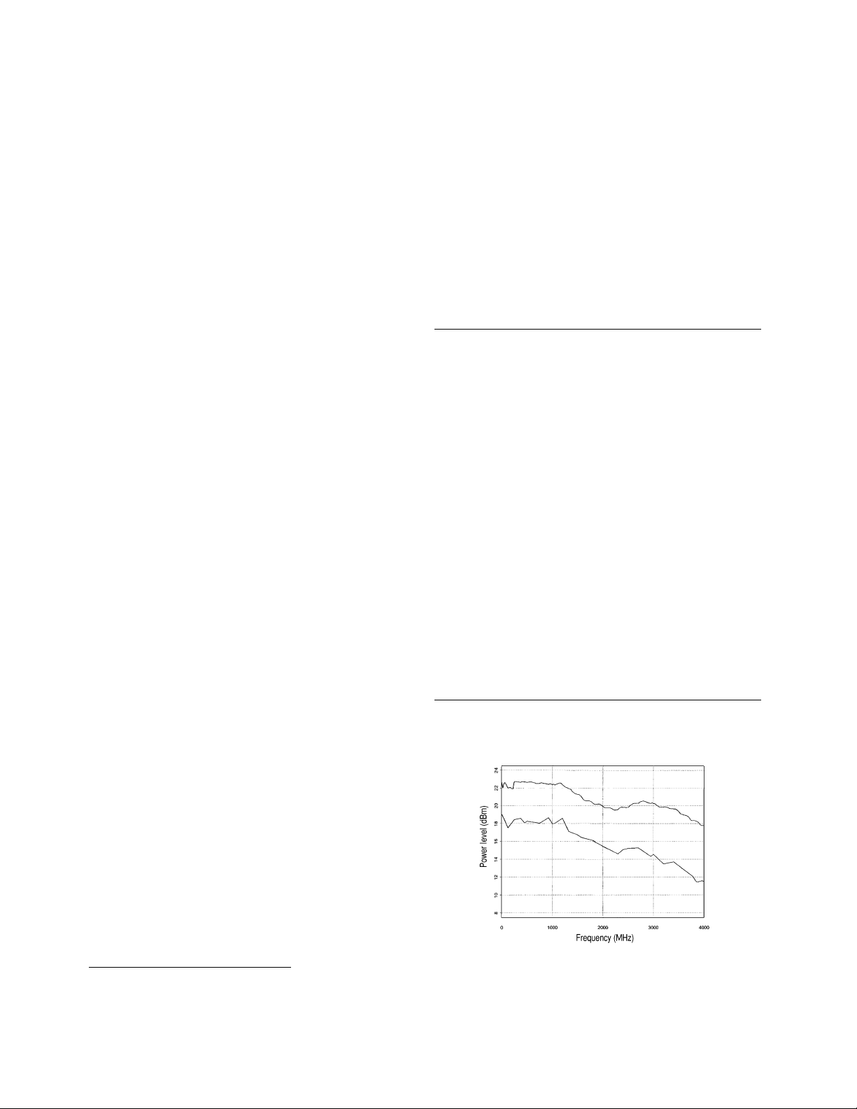
Characteristic ESG-A and ESG-D series SSB phase
noise at 1 GHz (phase noise modes 1 and 2)
Frequency (MHz)
Level error (dBm)
Option IE5
Standard
PN2
PN2
PN1
PN1
1. For 23 °C ±5 °C. Accuracy degrades by 0.02 dB/°C over the full temperature range and by 0.3 dB above +7 dBm (degraded by 0.5 dB above +10 dBm with Option UNB).
Level accuracy specification maintained only with return to calibration.
2. The reverse power protection circuitry triggers at nominally 1 watt.
3. Parentheses denote typical performance.
4. Refer to frequency bands on page 4 to compute specifications.
5. Performance is typical for spurs at frequencies above the maximum operating frequency of the instrument. Performance typically is –60 dBc between 225 and 249.999 MHz.
6. Specifications apply for FM deviations <100 kHz and are not valid for FM.
For non-constant amplitude digital formats, unspecified spur levels occur up to the second harmonic of the baseband rates.
7. Specifications apply for CW mode only.
6
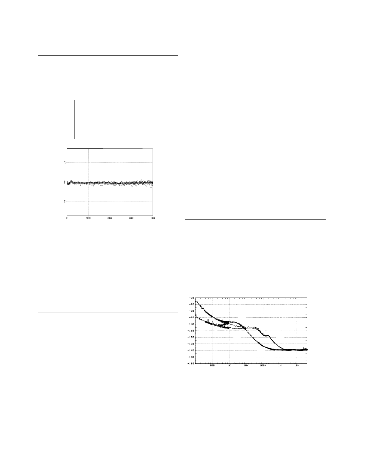
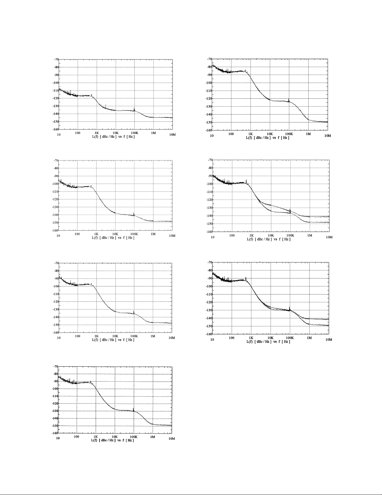
Characteristic SSB phase noise for ESG-AP and ESG-DP series
fc = 100 MHz (CW, standard instrument)
fc = 500 MHz (CW, standard instrument)
fc = 1 GHz (CW, standard instrument)
fc = 4 GHz (CW, standard instrument)
fc = 900 MHz (CW and I/Q modulation on)
fc = 1.8 GHz (CW and I/Q modulation on)
fc = 2 GHz (CW, standard instrument)

7
Frequency modulation
Maximum deviation
ESG-A and ESG-AP and
ESG-D series ESG-DP series
N x 10 MHz N x 1 MHz
Resolution 0.1% of deviation or 1 Hz,
whichever is greater
Modulation frequency response (deviation = 100 kHz)
1
Rates
1 dB bandwidth 3 dB bandwidth, typical
FM1 dc/20 Hz to 100 kHz dc/5 Hz to 10 MHz
FM2 dc/20 Hz to 100 kHz dc/5 Hz to 1 MHz
Deviation accuracy
2
<±(3.5% of FM deviation + 20 Hz)
(1 kHz rate, deviation < N x 100 kHz)
Carrier frequency accuracy relative
to CW in dcFM
2,3
±0.1% of set deviation + (N x 1 Hz)
Distortion
2
<1%
(1 kHz rate, THD, dev.= N x 100 kHz)
External inputs Ext 1 or Ext 2
Sensitivity 1 V
peak
for indicated deviation
Input impedance 50 Ω, nominal
Paths FM 1 and FM 2 are summed internally for composite modu-
lation. Either path may be switched to any one of the modulation
sources: Int, Ext 1, Ext 2. The FM 2 path is limited to a maximum
rate of 1 MHz. The FM 2 path must be set to a deviation less than
FM 1.
Phase modulation
Maximum deviation
2
ESG-A and ESG-D ESG-AP and ESG-DP
series series
Normal BW N x 90 radians N x 10 radians
High BW N x 2π radians N x 1 radian
Resolution 0.1% of set deviation
Modulation frequency response
2
ESG-A and ESG-D series
Maximum Rates (3 dB BW)
Mode deviation ΦM1 ΦM2
Normal BW N x 90 rad dc to 100 kHz dc to 100 kHz
High BW N x 2π rad dc to 1.5 MHz (typ) dc to 0.9 MHz (typ)
N x π/2 rad dc to 6 MHz (typ) dc to 1 MHz (typ)
ESG-AP and ESG-DP series
Maximum Rates (3 dB BW)
Mode deviation ΦM1 ΦM2
Normal BW N x 10 rad dc to 100 kHz dc to 100 kHz
High BW N x 1 rad dc to 1 MHz (typ) dc to 1 MHz (typ)
Deviation accuracy <±(5% of deviation + 0.01 radians)
(1 kHz rate, Normal BW mode)
Distortion
2
<1%
1 kHz rate, THD, dev <N x 90 rad (dev < N x 10 rad for ESG-AP
and ESG-DP series), Normal BW mode
External inputs Ext 1 or Ext 2
Sensitivity 1 V
peak
for indicated deviation
Input impedance 50 Ω, nominal
Paths ΦM 1 and ΦM 2 are summed internally for composite mod-
ulation. Either path may be switched to any one of the
modulation sources: Int, Ext 1, Ext 2. The ΦM 2 path is limited
to a maximum rate of 1 MHz. The ΦM 2 path must be set to a
deviation less than ΦM 1.
1. Since the internal modulation source operates over 0.1 Hz to 50 kHz, FM rates above 50 kHz must be supplied externally.
2. Refer to frequency bands on page 4 to compute specifications.
3. At the calibrated deviation and carrier frequency, within 5 °C of ambient temperature at time of calibration.

8
Amplitude modulation
1
(fc > 500 kHz)
Range 0 to 100%
(envelope peak ≤ maximum specified power)
Resolution 0.1%
Rates
(3 dB bandwidth) dc/10 Hz to 10 kHz
Accuracy
(1 kHz rate) < ± (6% of setting + 1%)
Distortion
(1 kHz rate, THD)
30% AM <1.5%
90% AM <4%, typical
External inputs Ext 1 or Ext 2
Sensitivity 1 V
peak
for indicated depth
Input impedance 50 Ω, nominal
Paths AM 1 and AM 2 are summed internally for composite mod-
ulation. Either path may be switched to any one of the modulation
sources: Int, Ext 1, Ext 2.
Wideband AM (ESG-DP and ESG-D series only)
Rate (1 dB bandwidth, typical)
ALC On 400 Hz to 10 MHz
ALC Off dc to 10 MHz
External input I input
Sensitivity 0.5 V = 100%
Input impedance 50 Ω, nominal
Pulse modulation
On/off ratio
≤3 GHz >80 dB
>3 GHz >60 dB
Rise/fall times 150 ns, typical
Minimum width
ALC On 2 µs, typical
ALC Off 0.4 µs, typical
Pulse repetition frequency
ALC On 10 Hz to 250 kHz, typical
ALC Off dc to 1.0 MHz, typical
Level accuracy
<±0.5 dB, typical
(relative to CW)
2
External input Ext 2
Input voltage
RF on >+0.5 V, nominal
RF off <+0.5 V, nominal
Input impedance 50 Ω, nominal
Internal pulse generator
Square wave rate 0.1 Hz to 50 kHz
Pulse
Period 16 µs to 30 sec
Width 8 µs to 30 sec
Resolution 4 µs
High-performance pulse modulation
(Option 1E6, ESG-AP and ESG-A series)
3
On/off ratio
≤2 GHz >80 dB
>2 GHz >70 dB
Rise/fall times <10 ns
Delay <60 ns, typical
External input Pulse in
Input voltage +5 V (with RF on, TTL compatible)
Input impedance
1. AM is typical above 3 GHz or if wideband AM or I/Q modulation is simultaneously enabled.
2. With ALC off, specifications apply after the execution of power search. With ALC on, specifications apply for pulse repetition rates ≤10 kHz and pulse widths ≥5µs.
3. With high performance pulse modulation (Option 1E6) installed, all maximum power specifications drop by 4 dB.

9
Internal modulation source
(Provides FM, ΦM, and AM modulation signals and LF out)
Waveforms sine, square, ramp, triangle,
pulse, noise
Rate range
Sine 0.1 Hz to 50 kHz
Square, ramp, triangle 0.1 Hz to 10 kHz
Resolution 0.1 Hz
Pulse only 4 µs
Frequency accuracy 0.005%, typical
Swept sine mode (frequency, phase continuous)
Operating modes Triggered or continuous sweeps
Frequency range 0.1 Hz to 50 kHz
Sweep time 1 ms to 65 sec
Resolution 1 ms
Dual sinewave mode
Frequency range 0.1 Hz to 50 kHz
Amplitude ratio 0 to 100%
Amplitude ratio resolution 0.1%
LF out (internal modulation source)
Amplitude 0 to 3 V
peak
into 50 Ω
Output impedance <1 Ω
External modulation inputs
Modulation types
Ext 1 FM, ΦM, AM, and burst envelope
Ext 2 FM, ΦM, AM, and pulse
High/Low Indicator (100 Hz to 10 MHz BW, AC coupled inputs
only) Activated when input level error exceeds 3% (nominal)
Simultaneous modulation
All modulation types may be simultaneously enabled, except: FM
with FM; AM with burst envelope; Wideband AM with I/Q. AM,
FM, and FM can sum simultaneous inputs from any two sources
(INT, EXT 1, and EXT 2.) Any given source (INT, EXT 1, or EXT 2)
may only be routed to one activated modulation type.
10
Level accuracy with digital modulation
(ESG-DP and ESG-D series only)
With ALC On; relative to CW; with PRBS modulated data;
if using I/Q inputs,
√ I
2
+ Q
2
= 0.5 V
rms
, nominal)
1
π/4 DQPSK or QPSK formats
ESG-D series ESG-DP series
±0.15 dB ±0.20 dB
(Relative to CW; with raised cosine or root-raised cosine filter and
α≥0.35; with 10 kHz ≤ symbol rate ≤1 MHz; at RF freq ≥25 MHz;
power ≤ max specified –3 dB or –6 dB with Option UNB)
Constant amplitude formats (FSK, GMSK, etc)
ESG-D series ESG-DP series
No degradation ±0.10 dB
Level accuracy with ALC off
2
±0.3 dB, typical
(After power search is executed; relative to CW level accuracy with
ALC on; with burst off; if external I/Q is enabled
√
I
2
+ Q
2
= 0.5 V
rms
)
I/Q modulation
(ESG-DP and ESG-D series only)
I/Q inputs
Input impedance 50 Ω
Full scale input
1
√ I
2
+ Q
2
= 0.5 V
rms
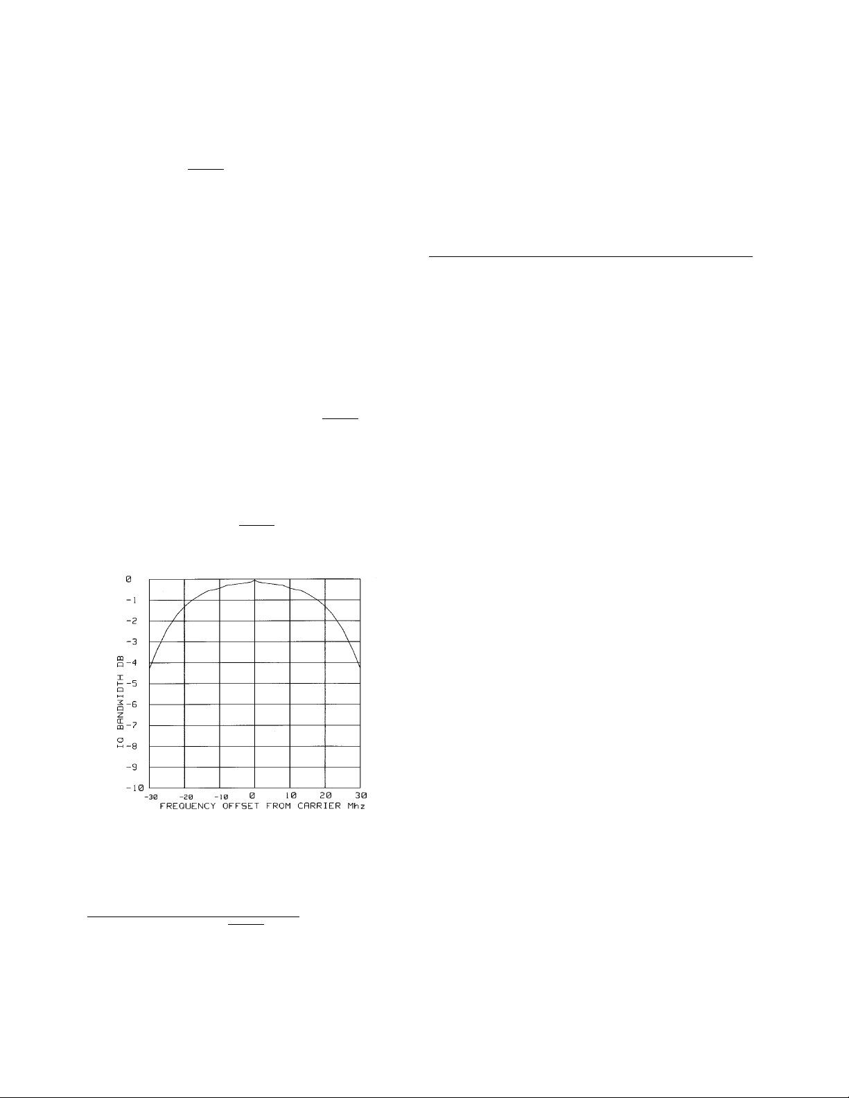
Typical I/Q frequency response
Adjustments/Impairments (nominal)
DC offset (I and Q independently adjustable) ±100%
I/Q gain ratio ±4 dB
I/Q quadrature ±10° (for fc ≤ 3.3 GHz)
DC vector accuracy
3
(Relative to full scale, power ≤ +7 dBm (≤+10 dBm, Option UNB))
Frequency (GHz) <0.6 0.6 to 2 2 to 3.7 ≤ 4
Static EVM
4
(rms) <0.75% <0.5% 0.75% <1%
Mag. error
4
(rms) <0.5% <0.35% <0.5% <0.75%
Phase error
4
(rms) <0.35° <0.25° <0.35° <0.5°
Origin offset (dBc) <–46 <–46 <–40 <–40
External burst envelope
(ESG-DP and ESG-D series only)
Input voltage
RF On 0 V
RF Off –1.0 V
Linear control range 0 to –1 V
On/off ratio
≤3 GHz >75 dB
>3 GHz >60 dB
V
in
≤–1.05 V
Rise/fall time <2 µs with rectangular input, typical
Minimum burst repetition frequency
ALC on 10 Hz, typical
ALC off dc
External input Ext 1
Input impedance 50 Ω, nominal
Coherent carrier out
5
(ESG-DP and ESG-D series only)
Range 250 MHz to maximum carrier
frequency
Level 0 dBm ±5 dB, typical
Impedance 50 Ω
Specifications for digital models only
1. The optimum I/Q input level is √ I
2
+Q
2
= 0.5 V
rms
, I/Q drive level affects EVM, origin offset, spectral regrowth, and noise floor. Typically, level accuracy with ALC on
will be maintained with drive levels between 0.25 and 1.0 V
rms
.
2. When applying external I/Q signals with ALC off, output level will vary directly with I/Q input level. Power search is an internal calibration routine used to set output
power when ALC is off. The routine disables all modulation inputs, adjusts output power while applying 0.5 V
rms
to the I/Q modulathen enables modulation.
3. Valid for 10 days after executing internal calibration routine, provided temperature is maintained within ±5 ˚C of calibration temperature.
4. Measured at full scale with origin offset removed.
5. Coherent carrier is modulated by FM or ΦM when enabled.
 Loading...