


P8H77-V LE
Motherboard

E7114
First Edition (V1)
February 2012
Copyright © 2012 ASUSTeK Computer Inc. All Rights Reserved.
No part of this manual, including the products and software described in it, may be reproduced, transmitted, transcribed, stored in a retrieval system, or translated into any language in any form or by any means, except documentation kept by the purchaser for backup purposes, without the express written permission of ASUSTeK Computer Inc. (“ASUS”).
Product warranty or service will not be extended if: (1) the product is repaired, modified or altered, unless such repair, modification of alteration is authorized in writing by ASUS; or (2) the serial number of the product is defaced or missing.
ASUS PROVIDES THIS MANUAL “AS IS” WITHOUT WARRANTY OF ANY KIND, EITHER EXPRESS OR IMPLIED, INCLUDING BUT NOT LIMITED TO THE IMPLIED WARRANTIES OR CONDITIONS OF MERCHANTABILITY OR FITNESS FOR A PARTICULAR PURPOSE. IN NO EVENT SHALL ASUS, ITS DIRECTORS, OFFICERS, EMPLOYEES OR AGENTS BE LIABLE FOR ANY INDIRECT, SPECIAL, INCIDENTAL, OR CONSEQUENTIAL DAMAGES (INCLUDING DAMAGES FOR LOSS OF PROFITS, LOSS OF BUSINESS, LOSS OF USE OR DATA, INTERRUPTION OF BUSINESS AND THE LIKE), EVEN IF ASUS HAS BEEN ADVISED OF THE POSSIBILITY OF SUCH DAMAGES ARISING FROM ANY DEFECT OR ERROR IN THIS MANUAL OR PRODUCT.
SPECIFICATIONS AND INFORMATION CONTAINED IN THIS MANUAL ARE FURNISHED FOR INFORMATIONAL USE ONLY, AND ARE SUBJECT TO CHANGE AT ANY TIME WITHOUT NOTICE, AND SHOULD NOT BE CONSTRUED AS A COMMITMENT BY ASUS. ASUS ASSUMES NO RESPONSIBILITY OR LIABILITY FOR ANY ERRORS OR INACCURACIES THAT MAY APPEAR IN THIS MANUAL, INCLUDING THE PRODUCTS AND SOFTWARE DESCRIBED IN IT.
Products and corporate names appearing in this manual may or may not be registered trademarks or copyrights of their respective companies, and are used only for identification or explanation and to the owners’ benefit, without intent to infringe.
Offer to Provide Source Code of Certain Software
This product may contain copyrighted software that is licensed under the General Public License (“GPL”) and under the Lesser General Public License Version (“LGPL”). The GPL and LGPL licensed code in this product is distributed without any warranty. Copies of these licenses are included in this product.
You may obtain the complete corresponding source code (as defined in the GPL) for the GPL Software, and/or the complete corresponding source code of the LGPL Software (with the complete machinereadable “work that uses the Library”) for a period of three years after our last shipment of the product including the GPL Software and/or LGPL Software, which will be no earlier than December 1, 2011, either
(1)for free by downloading it from http://support.asus.com/download;
or
(2)for the cost of reproduction and shipment, which is dependent on the preferred carrier and the location where you want to have it shipped to, by sending a request to:
ASUSTeK Computer Inc.
Legal Compliance Dept. 15 Li Te Rd.,
Beitou, Taipei 112
Taiwan
In your request please provide the name, model number and version, as stated in the About Box of the product for which you wish to obtain the corresponding source code and your contact details so that we can coordinate the terms and cost of shipment with you.
The source code will be distributed WITHOUT ANY WARRANTY and licensed under the same license as the corresponding binary/object code.
This offer is valid to anyone in receipt of this information.
ASUSTeK is eager to duly provide complete source code as required under various Free Open Source Software licenses. If however you encounter any problems in obtaining the full corresponding source code we would be much obliged if you give us a notification to the email address gpl@asus.com, stating the product and describing the problem (please do NOT send large attachments such as source code archives etc to this email address).
ii

Contents
Safety information....................................................................................... |
vi |
About this guide.......................................................................................... |
vi |
P8H77-V LE specifications summary...................................................... |
viii |
Chapter 1 |
Product introduction |
|
|
1.1 |
Welcome!....................................................................................... |
1-1 |
|
1.2 |
Package contents......................................................................... |
1-1 |
|
1.3 |
Special features............................................................................ |
1-1 |
|
|
1.3.1 |
Product highlights ............................................................ |
1-1 |
|
1.3.2 |
Innovative ASUS features ................................................ |
1-4 |
1.4 |
Before you proceed...................................................................... |
1-6 |
|
1.5 |
Motherboard overview................................................................. |
1-7 |
|
|
1.5.1 |
Placement direction ......................................................... |
1-7 |
|
1.5.2 |
Screw holes ..................................................................... |
1-7 |
|
1.5.3 |
Motherboard layout .......................................................... |
1-8 |
|
1.5.4 |
Layout contents . .............................................................. |
1-8 |
1.6 |
Central Processing Unit (CPU).................................................... |
1-9 |
|
|
1.6.1 |
Installing the CPU .......................................................... |
1-10 |
|
1.6.2 |
CPU heatsink and fan assembly installation ................. |
1-12 |
1.7 |
System memory.......................................................................... |
1-14 |
|
|
1.7.1 |
Overview ........................................................................ |
1-14 |
|
1.7.2 |
Memory configurations . ................................................. |
1-15 |
|
1.7.3 |
Installing a DIMM ........................................................... |
1-21 |
|
1.7.4 |
Removing a DIMM ......................................................... |
1-21 |
1.8 |
Expansion slots.......................................................................... |
1-22 |
|
|
1.8.1 |
Installing an expansion card .......................................... |
1-22 |
|
1.8.2 |
Configuring an expansion card ...................................... |
1-22 |
|
1.8.3 |
PCI Express 2.0 x1 slots ............................................... |
1-22 |
|
1.8.4 |
PCI Express 3.0/2.0 x16 slots ....................................... |
1-22 |
|
1.8.5 |
PCI slots . ....................................................................... |
1-22 |
1.9 |
Jumpers |
....................................................................................... |
1-23 |
1.10 |
Connectors.................................................................................. |
1-24 |
|
|
1.10.1 .................................................. |
Rear panel connectors |
1-24 |
|
1.10.2 ........................................................ |
Internal connectors |
1-26 |
1.11 |
Onboard .......................................................................switches |
1-32 |
|
1.12 |
Onboard .............................................................................LEDs |
1-33 |
|
iii

Contents
1.13 Software support........................................................................ |
1-34 |
|
1.13.1 |
Installing an operating system....................................... |
1-34 |
1.13.2 |
Support DVD information............................................... |
1-34 |
Chapter 2 |
BIOS information |
|
|
2.1 |
Managing and updating your BIOS............................................. |
2-1 |
|
|
2.1.1 |
ASUS Update utility......................................................... |
2-1 |
|
2.1.2 |
ASUS EZ Flash 2............................................................ |
2-2 |
|
2.1.3 |
ASUS CrashFree BIOS 3 utility....................................... |
2-3 |
|
2.1.4 |
ASUS BIOS Updater....................................................... |
2-4 |
2.2 |
BIOS setup program..................................................................... |
2-6 |
|
2.3 |
Main menu................................................................................... |
2-10 |
|
|
2.3.1 |
System Language [English]........................................... |
2-10 |
|
2.3.2 |
System Date [Day xx/xx/xxxx]....................................... |
2-10 |
|
2.3.3 |
System Time [xx:xx:xx].................................................. |
2-10 |
|
2.3.4 |
Security.......................................................................... |
2-10 |
2.4 |
Ai Tweaker menu........................................................................ |
2-12 |
|
|
2.4.1 |
Ai Overclock Tuner [Manual]......................................... |
2-13 |
|
2.4.2 |
Memory Frequency [Auto]............................................. |
2-13 |
|
2.4.3 |
iGPU Max. Frequency [xxx]........................................... |
2-13 |
|
2.4.4 |
EPU Power Saving Mode [Disabled]............................. |
2-13 |
|
2.4.5 |
GPU Boost [OK]............................................................ |
2-14 |
|
2.4.6 |
DRAM Timing Control.................................................... |
2-14 |
|
2.4.7 |
CPU Power Management.............................................. |
2-14 |
|
2.4.8 |
DIGI+ VRM.................................................................... |
2-15 |
|
2.4.9 |
CPU Voltage [Offset Mode]............................................ |
2-16 |
|
2.4.10 |
iGPU Voltage [Offset Mode]........................................... |
2-16 |
|
2.4.11 |
DRAM Voltage [Auto]..................................................... |
2-17 |
|
2.4.12 |
VCCSA Voltage [Auto]................................................... |
2-17 |
|
2.4.13 |
PCH Voltage [Auto]........................................................ |
2-17 |
|
2.4.14 |
CPU PLL Voltage [Auto]................................................ |
2-17 |
2.5 |
Advanced menu.......................................................................... |
2-18 |
|
|
2.5.1 |
CPU Configuration......................................................... |
2-18 |
|
2.5.2 |
PCH Configuration......................................................... |
2-20 |
|
2.5.3 |
SATA Configuration........................................................ |
2-20 |
|
2.5.4 |
System Agent Configuration.......................................... |
2-21 |
iv

Contents
|
2.5.5 |
USB Configuration......................................................... |
2-22 |
|
2.5.6 |
Onboard Devices Configuration.................................... |
2-22 |
|
2.5.7 |
APM............................................................................... |
2-23 |
|
2.5.8 |
Network Stack............................................................... |
2-23 |
2.6 |
Monitor menu.............................................................................. |
2-24 |
|
|
2.6.1 |
CPU Temperature / MB Temperature [xxxºC/xxxºF]...... |
2-24 |
2.6.2CPU / Chassis Fan Speed [xxxx RPM] or [Ignore] / [N/A]2-24
|
2.6.3 |
CPU Q-Fan Control [Enabled]....................................... |
2-24 |
|
2.6.4 |
Chassis Fan Speed Low Limit [600 RPM]..................... |
2-25 |
|
2.6.5 |
CPU Voltage, 3.3V Voltage, 5V Voltage, 12V Voltage... |
2-25 |
|
2.6.6 |
Anti Surge Support [Enabled]........................................ |
2-25 |
2.7 |
Boot menu................................................................................... |
2-26 |
|
|
2.7.1 |
Bootup NumLock State [On].......................................... |
2-26 |
|
2.7.2 |
Full Screen Logo [Enabled]........................................... |
2-26 |
|
2.7.3 |
Wait for ‘F1’ If Error [Enabled]........................................ |
2-26 |
|
2.7.4 |
Fast Boot [Enabled]....................................................... |
2-27 |
|
2.7.5 |
Option ROM Messages [Force BIOS]........................... |
2-27 |
|
2.7.6 |
CSM Support [Enabled]................................................. |
2-27 |
|
2.7.7 |
Setup Mode [EZ Mode].................................................. |
2-27 |
|
2.7.8 |
UEFI/Legacy Boot [Enabled both UEFI and Legacy].... |
2-27 |
|
2.7.9 |
PCI ROM Priority [Legacy ROM]................................... |
2-27 |
|
2.7.10 |
Boot Option Priorities..................................................... |
2-27 |
|
2.7.11 |
Boot Override................................................................ |
2-27 |
2.8 |
Tools menu.................................................................................. |
2-28 |
|
|
2.8.1 |
ASUS EZ Flash 2 Utility................................................. |
2-28 |
|
2.8.2 |
ASUS O.C. Profile......................................................... |
2-28 |
|
2.8.3 |
ASUS SPD Information................................................. |
2-28 |
2.9 |
Exit menu..................................................................................... |
2-29 |
|
Appendices
Notices....................................................................................................... |
A-1 |

Safety information
Electrical safety
•To prevent electric shock hazard, disconnect the power cable from the electric outlet before relocating the system.
•When adding or removing devices to or from the system, ensure that the power cables for the devices are unplugged before the signal cables are connected. If possible, disconnect all power cables from the existing system before you add a device.
•Before connecting or removing signal cables from the motherboard, ensure that all power cables are unplugged.
•Seek professional assistance before using an adapter or extension cord. These devices could interrupt the grounding circuit.
•Ensure that your power supply is set to the correct voltage in your area. If you are not sure about the voltage of the electrical outlet you are using, contact your local power company.
•If the power supply is broken, do not try to fix it by yourself. Contact a qualified service technician or your retailer.
Operation safety
•Before installing the motherboard and adding devices on it, carefully read all the manuals that came with the package.
•Before using the product, ensure that all cables are correctly connected and the power cables are not damaged. If you detect any damage, contact your dealer immediately.
•To avoid short circuits, keep paper clips, screws, and staples away from connectors, slots, sockets and circuitry.
•Avoid dust, humidity, and temperature extremes. Do not place the product in any area where it may become wet.
•Place the product on a stable surface.
•If you encounter technical problems with the product, contact a qualified service technician or your retailer.
About this guide
This user guide contains the information you need when installing and configuring the motherboard.
How this guide is organized
This guide contains the following parts:
•Chapter 1: Product introduction
This chapter describes the features of the motherboard and the new technology it supports.
•Chapter 2: BIOS information
This chapter tells how to change system settings through the BIOS Setup menus. Detailed descriptions of the BIOS parameters are also provided.
vi
Conventions used in this guide
To ensure that you perform certain tasks properly, take note of the following symbols used throughout this manual.
DANGER/WARNING: Information to prevent injury to yourself when trying to complete a task.
CAUTION: Information to prevent damage to the components when trying to complete a task.
IMPORTANT: Instructions that you MUST follow to complete a task.
NOTE: Tips and additional information to help you complete a task.
Where to find more information
Refer to the following sources for additional information and for product and software updates.
1.ASUS websites
The ASUS website provides updated information on ASUS hardware and software products. Refer to the ASUS contact information.
2.Optional documentation
Your product package may include optional documentation, such as warranty flyers, that may have been added by your dealer. These documents are not part of the standard package.
Typography
Bold text |
Indicates a menu or an item to select. |
Italics |
Used to emphasize a word or a phrase. |
<Key> |
Keys enclosed in the less-than and greater-than sign means |
|
that you must press the enclosed key. |
|
Example: <Enter> means that you must press the Enter or |
|
Return key. |
<Key1>+<Key2>+<Key3> |
If you must press two or more keys simultaneously, the key |
|
names are linked with a plus sign (+). |
|
Example: <Ctrl>+<Alt>+<D> |
vii

P8H77-V LE specifications summary
CPU
Chipset
Memory
Expansion slots
LGA1155 socket for Intel® 3rd/2nd Generation Core™ i7/ i5/ i3/
Pentium® / Celeron® Processors
Supports 22nm and 32nm CPU
Supports Intel® Turbo Boost Technology 2.0*
*The Turbo Boost Thchnology 2.0 support depends on the CPU types. ** Refer to www.asus.com for Intel® CPU support list.
Intel® H77 Express Chipset
4 x DIMM, maximum 32GB, DDR3 1866(O.C.)*/1600/1333/1066 MHz, non-ECC, un-buffered memory
Dual-channel memory architecture
Supports Intel® Extreme Memory Profile (XMP)
*Due to the CPU behavior, DDR3 1866 MHz memory module will run at DDR3 1800 MHz frequency as default.
**Hyper DIMM support is subject to the physical characteristics of individual CPUs. Some hyper DIMMs only support one DIMM per channel. Please refer to Memory QVL for details.
***Refer to www.asus.com or this User Manual for the Memory QVL(Qualified Vendors List).
****When you install a total memory of 4GB capacity or more, Windows® 32-bit operating system may only recognize less than
3GB. We recommend a maximum of 3GB system memory if you are using a Windows® 32-bit operating system.
1 x PCI Express 3.0/2.0 x16 slot [bue] (at x16 mode)*
1 x PCI Express 2.0 x16 slot [black] (at x4 mode, compatible with PCIe x1, x2 and x4 devices)
2 x PCI Express 2.0 x1 slot
3 x PCI slots
*PCIe 3.0 speed is supported by Intel® 3rd generation Core™ processors.
Graphics
Multi-GPU support
Integrated graphics processor - Intel® HD Graphics support Multi-VGA output support: HDMI, DVI and RGB port
-Supports HDMI with max. resolution up to 1920 x 1200 @60Hz
-Supports DVI with max. resolution up to 1920 x 1200 @60Hz
-Supports RGB with max. resolution 2048 x 1536@75Hz
-Supports Intel® InTru™ 3D/Insider™/Quick Sync Video/Clear Video
HD Technology/HD Graphics
-Maximum shared Memory of 1696 MB
Supports ATI® Quad-GPU CrossFireX™ Technology
Supports Lucidlogix® Virtu MVP™ Technology*
*LucidLogix® Virtu MVP™ supports Windows® 7 operating systems.
Storage |
Intel® H77 Express Chipset: |
|
|
- |
2 x Serial ATA 6.0 Gb/s connectors (gray) |
|
- |
4 x Serial ATA 3.0 Gb/s connectors (blue) |
|
- |
Intel Rapid Storage Technology supports RAID 0, 1, 5 and 10 |
|
- Supports Intel® Smart Response Technology, Intel® Rapid Start |
|
|
|
Technology, Intel® Smart Connect Technology* |
|
* |
Supports on Intel® Core™ processor family with Windows® 7 |
|
|
operating systems. |
(continued on the next page)
viii

P8H77-V LE specifications summary
LAN |
Realtek® RTL8111F Gigabit LAN controller |
|
|
Audio |
Realtek® 887 8-Channel High Definition Audio CODEC |
||
|
- Supports Jack-Detection, Multi-streaming and Front Panel |
||
|
|
Jack-Retasking |
|
|
- Optical S/PDIF out port at back I/O |
||
|
* Use a chassis with HD audio module in the front panel to |
||
|
|
support an 8-channel audio output |
|
USB |
Intel® H77 Express Chipset - supports ASUS USB 3.0 Boost |
||
|
UASP Mode* |
||
|
|
- 2 x USB 3.0/2.0 ports at mid-board for front panel support |
|
|
|
- 2 x USB 3.0/2.0 ports at back panel (blue) |
|
|
Intel® H77 Express Chipset |
||
|
|
- 10 x USB 2.0/1.1 ports (6 ports at mid-board, 4 ports at |
|
|
|
back panel) |
|
|
* The USB 3.0 ports only support Windows® 7 or later versions. |
||
|
|
UASP standard only supports Windows® 8. |
|
ASUS Unique |
ASUS DIGI+ VRM: |
||
Features |
- Digital Power Control: Digital Power Design for the CPU and |
||
|
|
iGPU |
|
|
- 4+1+1 Phase Power Design |
||
|
ASUS Exclusive Features |
||
|
- Network iControl featuring instant network bandwidth |
||
|
|
domination for top network program in use |
|
|
- USB 3.0 Boost featuring the latest USB 3.0 UASP standard |
||
|
- |
MemOK! |
|
|
- |
TurboV |
|
|
- |
Ai Charger |
|
- Disk Unlocker featuring 3TB+ HDD support
ASUS Protect 3.0 Technology
-ASUS EPU
-ASUS Anti-Surge Protection
-Low EMI Solution
-100% Solid Capacitors
ASUS Quiet Thermal Solution:
-ASUS Fanless Design: Stulish Heatsink solution
-ASUS FAN Xpert
ASUS EZ DIY:
-ASUS AI Suite II
-ASUS UEFI BIOS
-ASUS O.C. Tuner
-ASUS CrashFree BIOS 3
-ASUS EZ Flash 2
-ASUS My Logo 2
(continued on the next page)
ix

P8H77-V LE specifications summary
ASUS Exclusive
Overclocking Features
Back Panel I/O Ports
Internal I/O Connector
Precision Tweaker 2:
-vCore: Adjustable CPU voltage at 0.005V increment
-vCCSA: 191-step system agent voltage control
-vDRAM Bus: 191-step Memory voltage control
-vPCH: 191-step Chipset voltage control
-iGPU: 127-step iGPU voltage control
-vCPU_PLL: 1-step CPU & PCH PLL voltage control
SFS (Stepless Frequency Selection)
-BCLK/PCIE frequency tuning from 80MHz up to 300MHz at 1MHz increment
Overclocking Protection:
-ASUS C.P.R.(CPU Parameter Recall)
1 x PS/2 Keyboard/Mouse COMBO port
1 x HDMI Output port
1 x DVI Output port
1 x RGB Output port
1 x LAN (RJ45) port
2 x USB 3.0 ports
4 x USB 2.0/1.1 ports
1 x Optical S/PDIF Out
3-jack 8-channel Audio jack(s)
3 x USB 2.0/1.1 connectors support additional 6 USB 2.0/1.1 ports
1 x USB 3.0/2.0 connectors support additional 2 USB 3.0/2.0 ports
2 x SATA 6Gb/s connectors (gray)
4 x SATA 3Gb/s connectors (blue)
1 x 4-pin CPU Fan connector
1 x 3-pin Chassis Fan connector
1 x Front Panel Audio connector
1 x System Panel connector
1 x 24-pin ATX Power connector
1 x 8-pin ATX 12V Power connector
1 x S/PDIF Out connector
1 x MemOK! Button
1 x Clear CMOS jumper
1 x COM connector
|
BIOS |
64 Mb Flash ROM, UEFI BIOS, PnP, DMI2.0, WfM2.0, SM |
|
|
|
|
BIOS 2.5, ACPI 2.0a, Multi-language BIOS, ASUS EZ Flash 2, |
|
|
|
|
ASUS CrashFree BIOS 3, F12 PrintScreen function, F3 Shortcut |
|
|
|
|
function, and ASUS DRAM SPD (Serial Presence Detect) |
|
|
|
|
memory information |
|
|
|
Manageability |
WfM 2.0, DMI 2.0, WOL by PME, WOR by PME, PXE |
|
|
|
Accessories |
2 x Serial ATA 6.0Gb/s cables |
|
|
|
|
1 x I/O Shield |
|
|
|
|
1 x User’s manual |
|
|
|
|
1 x Support DVD |
|
|
|
|
(continued on the next page) |
|
|
|
|
|
|
|
P8H77-V LE specifications summary
Support DVD
Form Factor
Drivers
ASUS Utilities
ASUS Update
Anti-virus software (OEM version)
uATX Form Factor, 12”x 8.6” (30.5cm x 21.8cm)
* Specifications are subject to change without notice.
xi

xii
Chapter 1
Product introduction
1.1Welcome!
Thank you for buying an ASUS® P8H77-V LE motherboard!
The motherboard delivers a host of new features and latest technologies, making it another standout in the long line of ASUS quality motherboards!
Before you start installing the motherboard, and hardware devices on it, check the items in your package with the list below.
1.2Package contents
Check your motherboard package for the following items.
Motherboard |
ASUS P8H77-V LE motherboard |
Cables |
2 x Serial ATA 6.0Gb/s cables |
Accessories |
1 x I/O shield |
Application DVD |
ASUS motherboard support DVD |
Documentation |
User Manual |
If any of the above items is damaged or missing, contact your retailer.
1.3Special features
1.3.1Product highlights
LGA1155 socket for Intel® Second/Third Generation Core™ i7 / Core™ i5 / Core™ i3 / Pentium® / Celeron® Processors
This motherboard supports the Intel® 3rd/2nd generation Core™ i7/i5/ i3/Pentium®/Celeron® processors in the LGA1155 package, with iGPU, memory, and PCI Express controllers integrated to support onboard graphics out with dedicated chipsets, 2-channel (4 DIMMs) DDR3 memory, and 16 PCI Express 3.0/2.0 lanes. This provides great graphics performance. Intel® 3rd/2nd generation Core™ i7/i5/i3/Pentium®/Celeron® processors are among the most powerful and energy efficient CPUs in the world.
Chapter 1: Product introduction |
1-1 |
Intel® H77 Express Chipset
The Intel® H77 Express Chipset is a single-chipset designed to support the 1155 socket Intel® 3rd/2nd generation Core™ i7/i5/ i3/Pentium®/ Celeron® processors. It provides improved performance by utilizing serial point-to-point links, allowing increased bandwidth and stability.
Additionally, H77 chipset provides 4 USB 3.0 ports for 10 times faster data retrieval speed. Moreover, Intel® H77 Express Chipset can also enable iGPU function, letting users enjoy the latest Intel® integrated graphic performance.
Dual-Channel DDR3 1866(O.C.) / 1600 / 1333 / 1066MHz support
The motherboard supports DDR3 memory that features data transfer rates of 1866(O.C.) / 1600 / 1333 / 1066 MHz to meet the higher bandwidth requirements of the latest 3D graphics, multimedia, and Internet applications. The dual-channel DDR3 architecture enlarges the bandwidth of your system memory to boost system performance.
Native SATA 6.0 Gb/s support
The Intel® H77 Express Chipset natively supports next-generation Serial
ATA (SATA) storage interface. This motherboard delivers up to 6.0 Gb/s data transfer rates. Additionally, get enhanced scalability, faster data retrieval, double the bandwidth of current bus systems.
Complete USB 3.0 Integration
ASUS facilitates the strategic USB 3.0 accessibility for both the front and rear panel – 4 USB 3.0 ports in total. Experience the latest plug & play connectivity at speeds up to 10 times faster than USB 2.0. The P8H77-V
LE affords greater convenience to high speed connectivity.
PCI Express® 3.0
PCI Express® 3.0 (PCIe 3.0) is the latest PCI Express bus standard with improved encoding schemes that provide twice the performance of the current PCIe 2.0. The total bandwidth for a x16 link reaches a maximum of 32Gb/s, double the 16 Gb/s of PCIe 2.0 (in x16 mode). As such, PCIe 3.0 provides users an unprecendented data speeds, combined with the convenience and seamless transition offerred by complete backward compatibility with PCIe 1.0 and PCIe 2.0 devices. PCIe 3.0 will become a must-have feature for users who wish to improve and optimize graphic performance, as well as have the latest technology available to them.
PCI 3.0 speed is supported by Intel® 3rd generation Core™ processors.
1-2 |
ASUS P8H77-V LE |

S/PDIF out connector at the back I/O
This motherboard provides convenient connectivity to external home theater audio systems via the optical S/PDIF (SONY-PHILIPS Digital Interface) out connecor at the back I/O. The S/PDIF transfers digital audio without converting it to analog format and keeps the best signal quality.
Intel® Smart Response Technology SSD Speed with HDD Capacity
Intel® Smart Response Technology boosts overall system performance by using an installed fast SSD (min 18.6GB available capacity required) as a cache for frequently accessed data. Key benefits include reduced load and wait times, and lower power consumption through the elimination
of unnecessary hard drive spin. This technology combines SSD performance with hard drive capacity, operating up to 6X faster than a hard drive-only system.
*Intel® Smart Response Technology is supported by 3rd/2nd generation Intel® Core™ processor family on Windows® 7™ operating systems.
**Operating systems must be installed on the HDD to launch Intel® Smart Response Technology.
The capacity of the SSD is reserved for caching function.
Intel® Smart Connect Technology
Your computer could receive web updates with fresh content for selected applications, even when setting the system to sleep. This means less time waiting for applications to start, update and sync with the cloud, providing a more efficient way.
Intel® Rapid Start Technology
Allows your computer to quickly resume from a lowe-power hibernate state in seconds. Saving system memory to the designed SSD, provides your computer a faster wake-up response time, while keeping the energy use low.
ATI Quad-GPU CrossFireX™ Support
ATI's CrossFireX™ boosts image quality along with rendering speed, eliminating the need to scale down screen resolution to get high quality images. CrossFireX™ allows higher antialiasing, anisotropic filtering, shading and texture settings. Adjust your display configurations, experiment with the 3D settings, and check the effects with a real-time
3D-rendered previews within ATI Catalyst™ Control Center.
Chapter 1: Product introduction |
1-3 |
1.3.2Innovative ASUS features
ASUS DIGI+ VRM
Digital Power Control: Digital Power Design for the CPU and iGPU
All-new digital CPU power controls work perfectly together to match digital power signal (SVID) requests from the CPU, with ultra-fast sensing and response efficiently delivering precision power. Accurate delivery reduces waste, and provides more stable CPU Vcore voltages. Users can adjust CPU and its processor graphics (iGPU) voltages for various overclocking scenarios, with accurate input through UEFI BIOS tuning
or the exclusive ASUS interface. This proprietary design increases overclocking headroom to push performance to its full potential.
EPU
Energy Efficiency All Around
Tap into the world’s first real-time PC power saving chip through the AI Suite II utility. Get total system-wide energy optimization by automatically detecting current PC loadings and intelligently moderating power consumption. This also reduces fan noise and extends component longevity.
GPU Boost
Go to the Limit with iGPU Level Up!
GPU Boost accelerates the integrated GPU for extreme graphics performance. The user-friendly interface facilitates flexible frequency adjustments. It easily delivers stable system-level upgrades for every use.
ASUS UEFI BIOS
Flexible and Easy BIOS Interface
ASUS UEFI BIOS offers the first mouse-controlled graphical BIOS designed with selectable modes, providing a user-friendly interface that goes beyond the traditional keyboard-only controls. It also natively supports fully-utilized hard drives larger than 2.2TB in 64-bit operating systems.
ASUS exclusive interface
EZ Mode displays frequently-accessed info. Users can choose system performance settings, and drag and drop boot priorities. Advanced Mode for performance enthusiasts includes detailed DRAM settings via a dedicated memory info page for complete insight.
New upgrade! Quick and easy information for enhanced system control
-F12 BIOS snapshot hotkey for sharing UEFI information and troubleshooting
-New F3 Shortcut for most accessed information
-ASUS DRAM SPD (Serial Presence Detect) information for accessing memory information, detecting faulty DIMMs, and helping with difficult
POST situations.
1-4 |
ASUS P8H77-V LE |
ASUS TurboV
Feel the adrenaline rush of real-time OC-now a reality with the ASUS TurboV. This easy OC tool allows you to overclock without exiting or rebooting the OS; and its user-friendly interface makes overclock with just a few clicks away. Moreover, the ASUS OC profiles in TurboV provides the best O.C. settings in different scenarios.
Network iControl
With a one-click on/off button, the software currently in use is set as top priority over all other network programs, dominating the network bandwidth with ease. Moreover, you can prioritize your favorite software easily by configuring profiles through the intutive user interface. Within
the profile, programs can be pre-scheduled to run in a specific time period to avoid network clogging and long-waits on downloads. Auto PPPoE network connection gives a one-step setup and an intuitive network bandwidth control center.
Fanless Design: stylish heatsink solution
The stylish heatsink features a 0-dB thermal solution that offers users a noiseless PC environment. Not only the beautiful shape upgrades the visual enjoyment for motherboard users, but also the heatsink design lowers the temperature of the chipset and power phase area through high efficient heat-exchange. Combined with usability and aesthetics, the ASUS stylish heatsink will give users an extremely silent and cooling experience with the elegant appearance!
ASUS Fan Xpert
ASUS Fan Xpert intelligently allows you to adjust the CPU fan and chassis fan speeds according to different ambient temperatures caused by different climate conditions in different geographic regions and your
PC’s loading. The built-in variety of useful profiles offer flexible controls of fan speed to achieve a quiet and cool environment.
MemOK!
MemOK! quickly ensures memory boot compatibility. This remarkable memory rescue tool requires a mere push of the button to patch memory issues. MemOK! determines failsafe settings and dramatically improves your system boot success. Get your system up and running in no time.
Ai Charger
Ai Charger is ASUS fast-charging software that supports iPod, iPhone, and iPad.
•Check your USB mobile device if it fully supports the BC 1.1 function.
•The actual charging speed may vary with your USB device’s conditions.
Chapter 1: Product introduction |
1-5 |
USB 3.0 Boost
New ASUS USB 3.0 Boost technology supports UASP (USB Attached SCSI Protocol), the latest USB 3.0 standard. With USB 3.0 Boost technology, a USB device’s transmission speed is significantly increased up to 170%, adding to an already impressive fast USB 3.0 transfer speed.
ASUS software automatically accelerates data speeds for compatible
USB 3.0 peripherals without the need for any user interaction.
• The USAP standard support varies with models.
• Due to Intel® USB 3.0 controller limitation, USB 3.0 Boost does not support Windows® XP.
ASUS CrashFree BIOS 3
ASUS CrashFree BIOS 3 is an auto-recovery tool that allows you to restore a corrupted BIOS file using the bundled support DVD or USB flash disk that contains the latest BIOS file.
C.P.R. (CPU Parameter Recall)
The BIOS C.P.R. feature automatically restores the CPU default settings when the system hangs due to overclocking failure. C.P.R. eliminates the need to open the system chassis and clear the RTC data. Simply shut down and reboot the system, and the BIOS automatically restores the CPU parameters to their default settings.
ErP ready
The motherboard is European Union´s Energy-related Products (ErP) ready, and ErP requires products to meet certain energy efficiency requirements in regards to energy consumptions. This is in line with
ASUS vision of creating environment-friendly and energy-efficient products through product design and innovation to reduce carbon footprint of the product and thus mitigate environmental impacts.
1.4Before you proceed
Take note of the following precautions before you install motherboard components or change any motherboard settings.
• Unplug the power cord from the wall socket before touching any component.
•Before handling components, use a grounded wrist strap or touch a safely grounded object or a metal object, such as the power supply case, to avoid damaging them due to static electricity.
•Hold components by the edges to avoid touching the ICs on them.
•Whenever you uninstall any component, place it on a grounded antistatic pad or in the bag that came with the component.
•Before you install or remove any component, ensure that the ATX power supply is switched off or the power cord is detached from the power supply. Failure to do so may cause severe damage to the motherboard, peripherals, or components.
1-6 |
ASUS P8H77-V LE |
1.5Motherboard overview
Before you install the motherboard, study the configuration of your chassis to ensure that the motherboard fits into it.
Ensure that you unplug the power cord before installing or removing the motherboard. Failure to do so can cause you physical injury and damage motherboard components.
1.5.1Placement direction
When installing the motherboard, ensure that you place it into the chassis in the correct orientation. The edge with external ports goes to the rear part of the chassis as indicated in the image below.
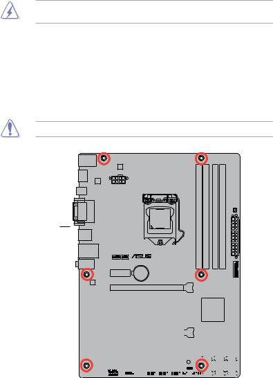
1.5.2Screw holes
Place six screws into the holes indicated by circles to secure the motherboard to the chassis.
Do not overtighten the screws! Doing so can damage the motherboard.
Place this side towards |
the rear of the chassis |
P8H77-V LE
|
|
|
|
|
|
|
|
|
|
|
|
|
|
|
|
|
|
|
|
|
|
|
|
|
|
|
|
|
|
|
|
|
|
|
|
|
|
|
|
|
|
|
|
|
|
|
|
|
|
|
|
|
|
|
|
|
|
|
|
|
|
|
|
|
|
|
|
|
|
|
|
|
|
|
|
|
|
|
|
|
|
|
|
|
|
|
|
|
|
|
|
|
|
|
|
|
|
|
|
|
|
|
|
|
|
|
|
|
|
|
|
|
|
|
|
|
|
|
|
|
|
|
|
|
|
|
|
|
|
|
|
|
|
|
|
|
|
|
|
|
|
|
|
|
|
|
|
|
|
|
|
|
|
|
|
|
|
|
|
|
|
|
|
|
|
|
|
|
|
|
|
|
|
|
|
|
|
|
|
|
|
|
|
|
|
|
|
|
|
|
|
|
|
|
|
|
|
|
|
|
|
|
|
|
|
|
|
|
|
|
|
|
|
|
|
|
|
|
|
|
|
|
|
|
|
|
|
|
|
|
|
|
|
|
|
|
|
|
|
|
|
|
|
|
|
|
|
|
|
|
|
|
|
|
|
|
|
|
|
|
|
|
|
|
|
|
|
|
|
|
|
|
|
|
|
|
|
|
|
|
|
|
|
|
|
|
|
|
|
|
|
|
|
|
|
|
|
|
|
|
|
|
|
|
|
|
|
|
|
|
|
|
|
|
|
|
|
|
|
|
|
|
|
|
|
|
|
|
|
|
|
|
|
|
|
|
|
|
|
|
|
|
|
|
|
|
|
|
|
|
|
|
|
|
|
|
|
|
|
|
|
|
|
|
|
|
|
|
|
|
|
|
|
|
|
|
|
|
|
|
|
|
|
|
|
|
|
|
|
|
|
|
|
|
|
|
|
|
|
|
|
|
|
|
|
|
|
|
|
|
|
|
|
|
|
|
|
|
|
|
|
|
|
|
|
|
|
|
|
|
|
|
|
|
|
|
|
|
|
|
|
|
|
|
|
|
|
|
|
|
|
|
|
|
|
|
|
|
|
|
|
|
|
|
|
|
|
|
|
|
|
|
|
|
|
|
|
|
|
|
|
|
|
|
|
|
|
|
|
|
|
|
|
|
|
|
|
|
|
|
|
|
|
|
|
|
|
|
|
|
|
|
|
|
|
|
|
|
|
|
|
|
|
|
|
|
|
|
|
|
|
|
|
|
|
|
|
|
|
|
|
|
|
|
|
|
|
|
|
|
|
|
|
|
|
|
|
|
|
|
|
|
|
|
|
|
|
|
|
|
|
|
|
|
|
|
|
|
|
|
|
|
|
|
|
|
|
|
|
|
|
|
|
|
|
|
|
|
|
|
|
|
|
|
|
|
|
|
|
|
|
|
|
|
|
|
|
|
|
|
|
|
|
|
|
|
|
|
|
|
|
|
|
|
|
|
|
|
|
|
|
|
|
|
|
|
|
|
|
|
|
|
|
|
|
|
|
|
|
|
|
|
|
|
|
|
|
|
|
|
|
|
|
|
|
|
|
|
|
|
|
|
|
|
|
|
|
|
|
|
|
|
|
|
|
|
|
|
|
|
|
|
|
|
|
|
|
|
|
|
|
|
|
|
|
|
|
|
|
|
|
|
|
|
|
|
|
|
|
|
|
|
|
|
|
|
|
|
|
|
|
|
|
|
|
|
|
|
|
Chapter 1: Product introduction |
1-7 |
||||||||||||||||||||||||||||||||||||||||||||||||
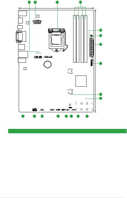
1.5.3Motherboard layout
1 |
2 |
3 |
4 |
|
|
21.8cm(8.6in) |
|
|
|
|
|
KB_USB34 |
|
|
|
|
|
|
|
|
DIGI |
|
|
|
|
|
|
|
+VRM |
|
|
|
|
|
|
HDMI |
|
|
|
|
|
|
|
|
ASM |
|
|
|
|
|
|
|
1442 |
|
|
|
|
|
|
|
EATX12V |
|
|
|
|
|
|
SPDIFO |
|
|
module) |
module) |
module) |
module) |
|
DVIVGA |
|
LGA1155 |
LEDDRAM |
||||
|
(64bit,240-pin |
(64bit,240-pin |
(64bit,240-pin |
(64bit,240-pin |
|||
|
|
|
|
|
|
|
MemOK! |
|
|
|
A1 |
A2 |
B1 |
B2 |
|
USB3_12 |
|
|
DIMM |
DIMM |
DIMM |
DIMM |
|
LAN_USB12 |
CPU_FAN |
CHA_FAN |
DDR3 |
DDR3 |
DDR3 |
DDR3 |
EATXPWR |
|
|
|
|
|
|
||
 AUDIO
AUDIO
|
|
|
|
|
PCIEX1_1 |
|
|
|
Lithium Cell |
|
|
|
|
|
|
|
|
|
|
|
|
|
|
|
|
|
|
|
|
|
||||||||||||
|
|
|
|
|
|
|
|
CMOS Power |
|
|
|
|
|
|
|
|
|
|
|
|
|
|
|
|
|
|
|
|
|
|||||||||||||
|
|
|
|
|
|
|
|
|
|
|
|
|
|
|
|
|
|
|
|
|
|
|
|
|
|
|
|
|
|
|
|
|
|
|
|
|
|
|
|
|
|
|
|
|
|
|
|
|
|
|
|
|
|
|
|
|
|
|
|
|
|
|
|
|
|
|
|
|
|
|
|
|
|
|
|
|
|
|
|
|
|
|
|
|
|
|
|
|
|
|
|
|
|
|
|
|
|
|
|
|
|
|
|
|
|
|
|
|
|
|
|
|
|
|
|
|
|
|
|
|
|
|
USB3_34 |
|||||
|
Realtek |
|
|
|
|
|
|
|
|
|
|
|
|
|
|
|
|
|
|
|
|
|
|
|
|
|
|
|
|
|
|
|
|
|
|
|
||||||
|
|
|
|
|
|
|
|
|
|
|
|
|
|
|
|
|
|
|
|
|
|
|
|
|
|
|
|
|
|
|
|
|
|
|
|
|
|
|
|
|
|
|
|
8111 |
|
|
|
|
|
|
|
|
|
|
|
|
|
|
|
|
|
|
|
|
|
|
|
|
|
|
|
|
|
|
|
|
|
|
|
|
|
|
|
|
|
|
|
|
|
|
|
|
|
|
|
|
|
|
|
|
|
|
|
|
|
|
|
|
|
|
|
|
|
|
|
|
|
|
|
|
|
|
|
|
|
|
|
|
|
|
|
|
|
|
|
|
|
|
|
|
|
PCIEX16_1 |
|
|
|
|
|
|
|
|
|
|
|
|
|
|
|
|
|
|
|
|
|
||||||||
|
|
|
|
|
|
|
|
|
|
|
|
|
|
|
|
|
|
|
|
|
|
|
|
|
|
|
|
|
|
|
|
|
|
|||||||||
|
|
|
|
|
|
|
|
|
P8H77-V LE |
|
|
|
|
|
|
|
|
|
|
|
|
|
|
|
|
|
|
|
|
|
||||||||||||
|
|
|
|
|
|
|
|
|
|
|
|
|
|
|
|
|
|
|
|
|
|
|
|
|
|
|
|
|
|
|
|
|
|
|
|
|
|
|
|
|
|
|
|
|
|
|
|
PCIEX1_2 |
|
|
|
|
|
|
|
|
|
|
|
|
|
|
|
|
|
|
|
|
|
|
Intel® |
|
|
|
|
|
|
||||||||
|
|
|
|
|
|
|
|
|
|
|
|
|
|
|
|
|
|
|
|
|
|
|
|
|
|
|
|
|
|
|
|
|
|
|
|
|
||||||
|
|
|
|
|
|
|
|
|
|
|
|
|
|
|
|
|
|
|
|
|
|
|
|
|
|
|
|
|
|
|
|
|
|
|
|
|||||||
|
|
|
|
|
|
|
|
|
|
|
|
|
|
|
|
|
|
|
|
|
|
|
|
|
|
|
|
|
|
|
H77 |
|
|
|
|
|
|
|||||
|
ASM |
|
|
|
|
|
|
|
|
|
|
PCI1 |
|
|
|
|
|
|
|
|
|
|
|
|
|
|
|
|
|
|
|
|
|
|||||||||
1083 |
|
|
|
|
|
|
|
|
|
|
|
|
|
|
|
|
|
|
|
|
|
|
|
|
|
|
|
|
|
|
|
|||||||||||
|
|
|
|
|
|
|
|
|
|
|
|
|
|
|
|
|
|
|
|
|
|
|
|
|
|
|
|
|
|
|
|
|
|
|
|
|
|
|
|
|||
|
|
|
|
|
|
|
|
|
|
|
|
|
|
|
|
|
|
|
|
|
|
|
|
|
|
|
|
|
|
|
|
|
|
|
|
|
|
|
|
|
|
|
|
|
|
|
|
|
|
|
|
|
|
|
|
|
|
|
|
|
|
|
|
|
|
|
|
|
|
|
|
|
|
|
|
|
|
|
|
||||||
|
|
|
|
|
|
|
|
|
|
|
|
|
PCIEX16_2 |
|
|
|
|
|
|
|
|
|
|
|
|
|
|
|
|
|
|
|
|
|
||||||||
|
Super |
|
|
|
|
|
|
|
|
|
|
|
|
|
|
|
|
|
|
|
|
|
|
|
|
|
|
|
|
|
|
|||||||||||
|
|
|
|
|
|
|
|
|
|
|
|
|
|
|
|
|
|
|
|
|
|
|
|
|
|
|
|
|
|
|
|
|
|
|
|
|
|
|
|
|
||
|
I/O |
|
|
|
|
|
|
|
|
|
|
|
|
|
|
|
|
|
|
|
|
|
|
|
|
|
|
|
|
|
|
|
|
|
|
|
|
|
|
|
|
|
|
|
|
|
|
|
|
|
|
|
|
|
|
PCI2 |
|
|
|
|
|
|
|
|
64Mb |
|
|
|
|
|
|
|
|
|
|
|
|
||||||||
|
|
|
|
|
|
|
|
|
|
|
|
|
|
|
|
|
|
|
|
|
BIOS |
|
|
|
|
|
|
|
|
|
|
|
|
|||||||||
|
ALC |
|
|
|
|
|
|
|
|
|
|
|
|
|
|
|
|
|
|
|
|
|
|
|
|
|
|
|
SATA3G_3 |
SATA3G_2 |
SATA3G_1 |
|
||||||||||
|
887 |
|
|
|
|
|
|
|
|
|
|
|
|
|
|
|
|
|
|
|
|
|
|
|
|
|
SB_PWR |
|
|
|
|
|
|
|
|
|
|
|
|
|
||
|
|
|
|
|
|
|
|
|
|
|
|
|
PCI3 |
|
|
|
|
|
|
|
|
|
|
|
|
|
|
|
|
|
|
|||||||||||
|
|
|
|
|
|
|
|
|
|
|
|
|
|
|
|
|
|
|
|
|
|
|
|
|
|
|
|
CLRTC |
|
|
|
|
|
|
|
|
|
|
|
|
|
|
|
SPDIF_OUT |
|
|
|
|
|
COM1 |
|
|
USB910 USB78 |
USB56 |
|
|
|
SATA3G_4 |
SATA6G_2 |
SATA6G_1 |
|||||||||||||||||||||||||
|
|
|
AAFP |
|
|
|
|
|
|
|
|
|
|
|
|
|
|
|
|
|
|
|
|
|
|
|
|
|
|
|
|
|
|
|
|
|
|
|
|
|
|
|
|
|
|
|
|
|
|
|
|
|
|
|
|
|
|
|
|
|
|
|
|
|
|
|
|
|
|
|
|
|
|
|
|
|
|
|
|
|
|
|
|
|
|
|
|
|
|
|
|
|
|
|
|
|
|
|
|
|
|
|
|
|
|
|
|
|
|
|
PANEL |
|
|
|
|
|
|
|
|
|
|
|
|
|
|
|||
|
|
|
|
|
|
|
|
|
|
|
|
|
|
|
|
|
|
|
|
|
|
|
|
|
|
|
|
|
|
|||||||||||||
|
|
|
|
|
|
|
|
|
|
|
|
|
|
|
|
|
|
|
|
|
|
|
|
|
|
|
|
|||||||||||||||
16 |
|
|
|
15 |
|
|
14 |
13 |
12 |
11 |
|
9 |
|
|
10 |
|
|
|
|
|
||||||||||||||||||||||
5
6
2
7
30.5cm(12.0in)
8
9
1.5.4Layout contents
|
Connectors/Jumpers/Slots/LED |
Page |
|
Connectors/Jumpers/Slots/LED |
Page |
1. |
CPU, chassis fan connectors (4-pin CPU_FAN, |
1-26 |
9. |
Intel® H77 Serial ATA 3.0Gb/s connectors |
1-30 |
|
3-pin CHA_FAN) |
|
|
(7-pin SATA3G_1~4 [blue]) |
|
2. |
ATX power connectors (24-pin EATXPWR, |
1-27 |
10 |
Intel® H77 Serial ATA 6.0Gb/s connectors |
1-29 |
|
8-pin EATX12V) |
|
|
(7-pin SATA6G_1/2 [gray]) |
|
3. |
Intel® LGA1155 CPU socket |
1-9 |
11. |
System panel connector (20-8 pin F_PANEL) |
1-31 |
4. |
DDR3 DIMM slots |
1-14 |
12. |
Clear RTC RAM (3-pin CLRTC) |
1-23 |
5. |
DRAM LED |
1-33 |
13. |
USB 2.0 connectors (10-1 pin USB5~10) |
1-28 |
6. |
MemOK! switch |
1-32 |
14. |
Serial port connectors (10-1 pin COM1) |
1-28 |
7. |
USB 3.0 connector (20-1 pin USB3_34) |
1-29 |
15. |
Front panel audio connector (10-1 pin AAFP) |
1-26 |
8. |
Onboard LED (SB_PWR) |
1-33 |
16. |
Digital audio connector (4-1 pin SPDIF_OUT) |
1-27 |
1-8 |
ASUS P8H77-V LE |
1.6Central Processing Unit (CPU)
The motherboard comes with a surface mount LGA1155 socket designed for the Intel®
3rd/2nd Generation Core™ i7/ i5/ i3/ Pentium® / Celeron® processors.
P8H77-V LE
P8H77-V LE CPU socket LGA1155
Unplug all power cables before installing the CPU.
• Upon purchase of the motherboard, ensure that the PnP cap is on the socket and the socket contacts are not bent. Contact your retailer immediately if the PnP cap is missing, or if you see any damage to the PnP cap/socket contacts/motherboard components. ASUS will shoulder the cost of repair only if the damage is shipment/transit-related.
•Keep the cap after installing the motherboard. ASUS will process Return Merchandise
Authorization (RMA) requests only if the motherboard comes with the cap on the
LGA1155 socket.
•The product warranty does not cover damage to the socket contacts resulting from incorrect CPU installation/removal, or misplacement/loss/incorrect removal of the PnP cap.
Chapter 1: Product introduction |
1-9 |
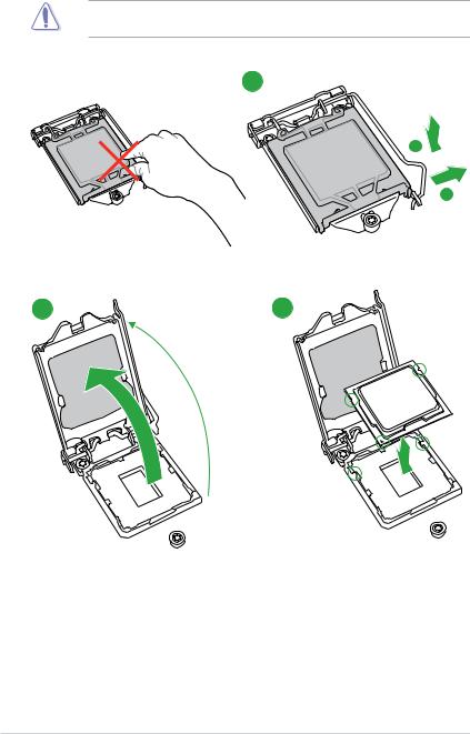
1.6.1Installing the CPU
The LGA1156 CPU is incompatible with the LGA1155 socket. DO NOT install a LGA1156 CPU on the LGA1155 socket.
1
A
B
2 |
3 |
1-10 |
ASUS P8H77-V LE |
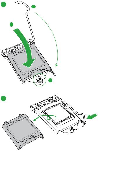
4 C
A
5
Chapter 1: Product introduction |
1-11 |

1.6.2CPU heatsink and fan assembly installation
Apply the Thermal Interface Material to the CPU heatsink and CPU before you install the heatsink and fan if necessary.
To install the CPU heatsink and fan assembly
1 A 2
2
B
B
A
3 |
4 |
1-12 |
ASUS P8H77-V LE |
 Loading...