


ASUS P5VDC-MX V2.0 User Manual

P5VDC-MX
Motherboard

E2545E2545
E2545
E2545E2545
Revised Edition V2Revised Edition V2
Revised Edition V2
Revised Edition V2Revised Edition V2
March 2006March 2006
March 2006
March 2006March 2006
Copyright © 2006 ASUSTeK COMPUTER INC. All Rights Reserved.
No part of this manual, including the products and software described in it, may be reproduced,
transmitted, transcribed, stored in a retrieval system, or translated into any language in any form
or by any means, except documentation kept by the purchaser for backup purposes, without the
express written permission of ASUSTeK COMPUTER INC. (“ASUS”).
Product warranty or service will not be extended if: (1) the product is repaired, modified or
altered, unless such repair, modification of alteration is authorized in writing by ASUS; or (2)
the serial number of the product is defaced or missing.
ASUS PROVIDES THIS MANUAL “AS IS” WITHOUT WARRANTY OF ANY KIND, EITHER
EXPRESS OR IMPLIED, INCLUDING BUT NOT LIMITED TO THE IMPLIED WARRANTIES
OR CONDITIONS OF MERCHANTABILITY OR FITNESS FOR A PARTICULAR PURPOSE.
IN NO EVENT SHALL ASUS, ITS DIRECTORS, OFFICERS, EMPLOYEES OR AGENTS BE
LIABLE FOR ANY INDIRECT, SPECIAL, INCIDENTAL, OR CONSEQUENTIAL DAMAGES
(INCLUDING DAMAGES FOR LOSS OF PROFITS, LOSS OF BUSINESS, LOSS OF USE
OR DATA, INTERRUPTION OF BUSINESS AND THE LIKE), EVEN IF ASUS HAS BEEN
ADVISED OF THE POSSIBILITY OF SUCH DAMAGES ARISING FROM ANY DEFECT OR
ERROR IN THIS MANUAL OR PRODUCT.
SPECIFICATIONS AND INFORMATION CONTAINED IN THIS MANUAL ARE FURNISHED
FOR INFORMATIONAL USE ONLY, AND ARE SUBJECT TO CHANGE AT ANY TIME
WITHOUT NOTICE, AND SHOULD NOT BE CONSTRUED AS A COMMITMENT BY ASUS.
ASUS ASSUMES NO RESPONSIBILITY OR LIABILITY FOR ANY ERRORS OR
INACCURACIES THAT MAY APPEAR IN THIS MANUAL, INCLUDING THE PRODUCTS
AND SOFTWARE DESCRIBED IN IT.
Products and corporate names appearing in this manual may or may not be registered
trademarks or copyrights of their respective companies, and are used only for identification or
explanation and to the owners’ benefit, without intent to infringe.
iiii
ii
iiii

Contents
Notices ................................................................................................ vi
Safety information ............................................................................. vii
About this guide ............................................................................... viii
P5VDC-MX specifications summary ..................................................... x
Chapter 1: Product introductionChapter 1: Product introduction
Chapter 1: Product introduction
Chapter 1: Product introductionChapter 1: Product introduction
1.1 Welcome! .............................................................................. 1-2
1.2 Package contents ................................................................. 1-2
1.3 Special features .................................................................... 1-2
1.3.1 Product highlights ................................................... 1-2
1.3.2 Innovative ASUS features ....................................... 1-4
1.4 Before you proceed .............................................................. 1-5
1.5 Motherboard overview .......................................................... 1-6
1.5.1 Placement direction ................................................ 1-6
1.5.2 Screw holes ............................................................ 1-6
1.5.3 Motherboard layout ................................................ 1-7
1.6 Central Processing Unit (CPU) .............................................. 1-8
1.6.1 Installling the CPU ................................................... 1-8
1.6.2 Installling the CPU heatsink and fan ..................... 1-11
1.6.3 Uninstalling the CPU heatsink and fan .................. 1-13
1.7 System memory ................................................................. 1-15
1.7.1 Overview ............................................................... 1-15
1.7.2 Memory Configurations ......................................... 1-15
1.7.3 DDR Qualified Vendors List ................................... 1-16
1.7.4 Installing a DDR DIMM (blue slots) ........................ 1-18
1.7.5 Removing a DDR DIMM .......................................... 1-18
1.7.6 Installing a DDR2 DIMM (yellow slots) .................. 1-19
1.7.7 Removing a DDR2 DIMM ........................................ 1-19
1.8 Expansion slots ................................................................... 1-20
1.8.1 Installing an expansion card .................................. 1-20
1.8.2 Configuring an expansion card .............................. 1-20
1.8.3 Interrupt assignments .......................................... 1-21
1.8.4 PCI slots ................................................................ 1-22
1.8.5 PCI Express x1 slot ............................................... 1-22
1.8.6 AGP slot ................................................................ 1-22
iiiiii
iii
iiiiii

Contents
1.9 Jumpers .............................................................................. 1-23
1.10 Connectors .........................................................................1-25
1.10.1 Rear panel connectors .......................................... 1-25
1.10.2 Internal connectors ...............................................1-26
Chapter 2: BIOS setupChapter 2: BIOS setup
Chapter 2: BIOS setup
Chapter 2: BIOS setupChapter 2: BIOS setup
2.1 Managing and updating your BIOS ........................................ 2-2
2.1.1 Creating a bootable floppy disk .............................. 2-2
2.1.2 ASUS EZ Flash utility .............................................. 2-3
2.1.3 AFUDOS utility ........................................................ 2-4
2.1.4 ASUS CrashFree BIOS 2 utility ................................ 2-6
2.1.5 ASUS Update utility ................................................ 2-8
2.2 BIOS setup program ........................................................... 2-11
2.2.1 BIOS menu screen ................................................. 2-12
2.2.2 Menu bar ............................................................... 2-12
2.2.3 Navigation keys .................................................... 2-12
2.2.4 Menu items ...........................................................2-13
2.2.5 Sub-menu items ................................................... 2-13
2.2.6 Configuration fields .............................................. 2-13
2.2.7 Pop-up window ..................................................... 2-13
2.2.8 Scroll bar .............................................................. 2-13
2.2.9 General help .......................................................... 2-13
2.3 Main menu .......................................................................... 2-14
2.3.1 System Time [xx:xx:xxxx] .....................................2-14
2.3.2 System Date [Day xx/xx/xxxx] ............................ 2-14
2.3.3 Legacy Diskette A [1.44M, 3.5 in.]......................2-14
2.3.4 Primary and Secondary IDE Master/Slave ............. 2-15
2.3.5 System Information ..............................................2-16
2.4 Advanced menu .................................................................. 2-17
2.4.1 JumperFree Configuration ....................................2-17
2.4.2 USB Configuration ................................................. 2-18
2.4.3 CPU Configuration ................................................. 2-19
2.4.4 Chipset ................................................................. 2-20
2.4.5 Onboard Devices Configuration ............................ 2-24
iviv
iv
iviv

Contents
2.4.6 PCI PnP ................................................................. 2-25
2.5 Power menu ........................................................................ 2-27
2.5.1 Suspend Mode [Auto] .......................................... 2-27
2.5.2 Repost Video on S3 Resume [No] ........................2-27
2.5.3 ACPI 2.0 Support [No] ......................................... 2-27
2.5.4 ACPI APIC Support [Enabled] ................................ 2-27
2.5.5 APM Configuration ................................................ 2-28
2.5.6 Hardware Monitor ................................................. 2-29
2.6 Boot menu .......................................................................... 2-30
2.6.1 Boot Device Priority .............................................. 2-30
2.6.2 Boot Settings Configuration .................................2-31
2.6.3 Security ................................................................ 2-32
2.7 Exit menu ........................................................................... 2-34
Chapter 3: Software supportChapter 3: Software support
Chapter 3: Software support
Chapter 3: Software supportChapter 3: Software support
3.1 Installing an operating system ............................................. 3-2
3.2 Support CD information ........................................................ 3-2
3.2.1 Running the support CD ......................................... 3-2
3.2.2 Drivers menu .......................................................... 3-3
3.2.3 Utilities menu .......................................................... 3-4
3.2.4 Make Disk menu ...................................................... 3-5
3.2.5 Manuals menu ......................................................... 3-5
3.2.6 ASUS Contact information ...................................... 3-6
3.3 RAID configurations .............................................................. 3-7
3.3.1 Installing hard disks ................................................ 3-8
3.4 Creating a RAID driver disk ................................................. 3-12
vv
v
vv

Notices
Federal Communications Commission StatementFederal Communications Commission Statement
Federal Communications Commission Statement
Federal Communications Commission StatementFederal Communications Commission Statement
This device complies with Part 15 of the FCC Rules. Operation is subject to
the following two conditions:
•
This device may not cause harmful interference, and
•
This device must accept any interference received including interference
that may cause undesired operation.
This equipment has been tested and found to comply with the limits for a
Class B digital device, pursuant to Part 15 of the FCC Rules. These limits are
designed to provide reasonable protection against harmful interference in a
residential installation. This equipment generates, uses and can radiate radio
frequency energy and, if not installed and used in accordance with
manufacturer’s instructions, may cause harmful interference to radio
communications. However, there is no guarantee that interference will not
occur in a particular installation. If this equipment does cause harmful
interference to radio or television reception, which can be determined by
turning the equipment off and on, the user is encouraged to try to correct
the interference by one or more of the following measures:
•
Reorient or relocate the receiving antenna.
•
Increase the separation between the equipment and receiver.
•
Connect the equipment to an outlet on a circuit different from that to
which the receiver is connected.
•
Consult the dealer or an experienced radio/TV technician for help.
The use of shielded cables for connection of the monitor to the graphics
card is required to assure compliance with FCC regulations. Changes or
modifications to this unit not expressly approved by the party
responsible for compliance could void the user’s authority to operate
this equipment.
Canadian Department of Communications StatementCanadian Department of Communications Statement
Canadian Department of Communications Statement
Canadian Department of Communications StatementCanadian Department of Communications Statement
This digital apparatus does not exceed the Class B limits for radio noise
emissions from digital apparatus set out in the Radio Interference
Regulations of the Canadian Department of Communications.
This class B digital apparatus complies with CanadianThis class B digital apparatus complies with Canadian
This class B digital apparatus complies with Canadian
This class B digital apparatus complies with CanadianThis class B digital apparatus complies with Canadian
ICES-003.ICES-003.
ICES-003.
ICES-003.ICES-003.
vivi
vi
vivi

Safety information
Electrical safetyElectrical safety
Electrical safety
Electrical safetyElectrical safety
•
To prevent electrical shock hazard, disconnect the power cable from
the electrical outlet before relocating the system.
•
When adding or removing devices to or from the system, ensure that
the power cables for the devices are unplugged before the signal cables
are connected. If possible, disconnect all power cables from the existing
system before you add a device.
•
Before connecting or removing signal cables from the motherboard,
ensure that all power cables are unplugged.
•
Seek professional assistance before using an adapter or extension cord.
These devices could interrupt the grounding circuit.
•
Make sure that your power supply is set to the correct voltage in your
area. If you are not sure about the voltage of the electrical outlet you
are using, contact your local power company.
•
If the power supply is broken, do not try to fix it by yourself. Contact a
qualified service technician or your retailer.
Operation safetyOperation safety
Operation safety
Operation safetyOperation safety
•
Before installing the motherboard and adding devices on it, carefully read
all the manuals that came with the package.
•
Before using the product, make sure all cables are correctly connected
and the power cables are not damaged. If you detect any damage,
contact your dealer immediately.
•
To avoid short circuits, keep paper clips, screws, and staples away from
connectors, slots, sockets and circuitry.
•
Avoid dust, humidity, and temperature extremes. Do not place the
product in any area where it may become wet.
•
Place the product on a stable surface.
•
If you encounter technical problems with the product, contact a qualified
service technician or your retailer.
This symbol of the crossed out wheeled bin indicates that the product
(electrical and electronic equipment) should not be placed in municipal
waste.
Please check local regulations for disposal of electronic products.
viivii
vii
viivii

About this guide
This user guide contains the information you need when installing and
configuring the motherboard.
How this guide is organizedHow this guide is organized
How this guide is organized
How this guide is organizedHow this guide is organized
This manual contains the following parts:
••
Chapter 1: Product introductionChapter 1: Product introduction
•
Chapter 1: Product introduction
••
Chapter 1: Product introductionChapter 1: Product introduction
This chapter describes the features of the motherboard and the new
technology it supports. This chapter also lists the hardware setup
procedures that you have to perform when installing system
components. It includes description of the jumpers and connectors on
the motherboard.
••
Chapter 2: BIOS setupChapter 2: BIOS setup
•
Chapter 2: BIOS setup
••
Chapter 2: BIOS setupChapter 2: BIOS setup
This chapter tells how to change system settings through the BIOS
Setup menus. Detailed descriptions of the BIOS parameters are also
provided.
••
Chapter 3: Software supportChapter 3: Software support
•
Chapter 3: Software support
••
Chapter 3: Software supportChapter 3: Software support
This chapter describes the contents of the support CD that comes
with the motherboard package.
Where to find more informationWhere to find more information
Where to find more information
Where to find more informationWhere to find more information
Refer to the following sources for additional information and for product
and software updates.
1.1.
ASUS websitesASUS websites
1.
ASUS websites
1.1.
ASUS websitesASUS websites
The ASUS website provides updated information on ASUS hardware
and software products. Refer to the ASUS contact information.
2.2.
Optional documentationOptional documentation
2.
Optional documentation
2.2.
Optional documentationOptional documentation
Your product package may include optional documentation, such as
warranty flyers, that may have been added by your dealer. These
documents are not part of the standard package.
viiiviii
viii
viiiviii
Conventions used in this guideConventions used in this guide
Conventions used in this guide
Conventions used in this guideConventions used in this guide
To make sure that you perform certain tasks properly, take note of the
following symbols used throughout this manual.
DANGER/WARNING: DANGER/WARNING:
DANGER/WARNING: Information to prevent injury to yourself
DANGER/WARNING: DANGER/WARNING:
when trying to complete a task.
CAUTION:CAUTION:
CAUTION: Information to prevent damage to the components
CAUTION:CAUTION:
when trying to complete a task.
IMPORTANT: IMPORTANT:
IMPORTANT: Instructions that you MUST follow to complete a
IMPORTANT: IMPORTANT:
task.
NOTE: NOTE:
NOTE: Tips and additional information to help you complete a
NOTE: NOTE:
task.
Typography
Bold textBold text
Bold text Indicates a menu or an item to select
Bold textBold text
Italics
<Key> Keys enclosed in the less-than and greater-than sign means
<Key1+Key2+Key3> If you must press two or more keys simultaneously, the
Command Means that you must type the command exactly as shown,
Used to emphasize a word or a phrase
that you must press the enclosed key
Example: <Enter> means that you must press the Enter or
Return key
key names are linked with a plus sign (+)
Example: <Ctrl+Alt+D>
then supply the required item or value enclosed in
brackets
Example: At the DOS prompt, type the command line:
afudos /i[filename]
afudos /iP5VDCMX.ROM
ixix
ix
ixix
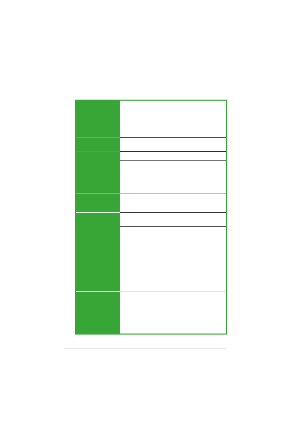
P5VDC-MX specifications summary
CPUCPU
CPU
CPUCPU
ChipsetChipset
Chipset
ChipsetChipset
Front Side BusFront Side Bus
Front Side Bus
Front Side BusFront Side Bus
MemoryMemory
Memory
MemoryMemory
Expansion slotsExpansion slots
Expansion slots
Expansion slotsExpansion slots
VGAVGA
VGA
VGAVGA
StorageStorage
Storage
StorageStorage
LGA775 socket for Intel® Pentium® D/Pentium® 4/
Celeron CPU Compatible with Intel®
04A processor
Supports Intel® EM64T/Hyper-Threading Technology
(Note: Due to chipset limitation, the Intel Enhanced Intel
SpeedStep Technology, C1E, and TM2 are not
supported in this model)
Northbridge: VIA P4M800 PRO
Southbridge: VIA VT8251
800/533 MHz
2 x 240-pin DIMM sockets support max. 2GB DDR2
533/400 non-ECC, unbuffered memory.
2 x 184-pin DIMM sockets support max. 2GB DDR 400/
333/266 non-ECC, unbuffered memory
(Note:DDR and DDR2 memory can not be used
simulltaneously)
1 x AGP 8X/4X (1.5V only)
1 x PCI Express x1
2 x PCI, PCI 2.2
Integrated VIA UniChrome Graphics, up to 64MB shared
memory
South Bridge: VT8251
2 x UltraDMA 133/100/66
4 x Serial ATA 3Gb/s with RAID 0, 1, 0+1 & JBOD
function
05B/05A and 04B/
LANLAN
LAN
LANLAN
AudioAudio
Audio
AudioAudio
Other ASUSOther ASUS
Other ASUS
Other ASUSOther ASUS
Special FeaturesSpecial Features
Special Features
Special FeaturesSpecial Features
Back panel I/OBack panel I/O
Back panel I/O
Back panel I/OBack panel I/O
PortsPorts
Ports
PortsPorts
xx
x
xx
Realtek RTL8201CL 10/100 LAN controller
Realtek ALC653 AC’97 6-channel Audio CODEC
ASUS Q-Fan
ASUS EZ Flash
CrashFree BIOS 2
ASUS MyLogo
1 x Parallel port
1 x RJ-45
4 x USB 2.0/1.1
1 x VGA out
1 x Serial port
1 x PS/2 keyboard
1 x PS/2 mouse
1 x 6-Channel Audio I/O
(continued on the next page)

P5VDC-MX specifications summary
BIOSBIOS
BIOS
BIOSBIOS
ManageabilityManageability
Manageability
ManageabilityManageability
USBUSB
USB
USBUSB
Internal I/OInternal I/O
Internal I/O
Internal I/OInternal I/O
connectorsconnectors
connectors
connectorsconnectors
Form FactorForm Factor
Form Factor
Form FactorForm Factor
Support CDSupport CD
Support CD
Support CDSupport CD
contentscontents
contents
contentscontents
4 Mb Flash ROM, AMI BIOS, PnP, WfM2.0, DMI2.0,
SM BIOS 2.3
WOL by PME, WOR by PME, Chassis Intrussion, PXE, RPL
Max. 8 USB 2.0 ports
2 x USB 2.0/1.1 connector supports additional 4 USB
ports
4 x SATA connector
2 x IDE connector
CPU/Chassis fan connectors
Game/MIDI connector
24-pin EATX Power connector
4-pin ATX 12 V Power connector
CD/AUX audio-in connector
Chassis Intrusion
1 x Floppy disk drive connector
1 x S/PDIF out connector
Front panel audio connector
System panel connector
mATX Form Factor, 9.6 in x 9.6 in (24.5 cm x 24.5 cm)
Drivers
ASUS PC Probe
ASUS Live Update utility
Anti-virus software (OEM version)
*Specifications are subject to change without notice.
xixi
xi
xixi

xiixii
xii
xiixii

This chapter describes the motherboard
features and the new technologies
it supports.
introduction
Product
1
ASUS P5VDC-MXASUS P5VDC-MX
ASUS P5VDC-MX
ASUS P5VDC-MXASUS P5VDC-MX
1-11-1
1-1
1-11-1
1.1 Welcome!
®®
®
Thank you for buying an ASUSThank you for buying an ASUS
Thank you for buying an ASUS
Thank you for buying an ASUSThank you for buying an ASUS
The motherboard delivers a host of new features and latest technologies,
making it another standout in the long line of ASUS quality motherboards!
Before you start installing the motherboard, and hardware devices on it,
check the items in your package with the list below.
®®
P5VDC-MX motherboard! P5VDC-MX motherboard!
P5VDC-MX motherboard!
P5VDC-MX motherboard! P5VDC-MX motherboard!
1.2 Package contents
Check your motherboard package for the following items.
MotherboardMotherboard
Motherboard ASUS P5VDC-MX motherboard
MotherboardMotherboard
CablesCables
Cables 1 x Serial ATA power cable
CablesCables
1 x Serial ATA signal cable
1 x Ultra DMA 133/100 cables
1 x Floppy disk drive cable
AccessoriesAccessories
Accessories I/O shield
AccessoriesAccessories
Application CDsApplication CDs
Application CDs ASUS motherboard support CD
Application CDsApplication CDs
DocumentationDocumentation
Documentation User guide
DocumentationDocumentation
If any of the above items is damaged or missing, contact your retailer.
1.3 Special features
1.3.11.3.1
1.3.1
1.3.11.3.1
Latest processor technology Latest processor technology
Latest processor technology
Latest processor technology Latest processor technology
The motherboard comes with a 775-pin surface mount Land Grid Array
(LGA) socket designed for the Intel® Pentium® 4 processor in the 775-land
package. The motherboard supports the Intel® Pentium® 4 processor with
800 MHz Front Side Bus (FSB), and core speed of up to 3.8 GHz. The
motherboard also supports the Intel® Hyper-Threading Technology and is
fully compatible with Intel® 05B/05A and 04B/04A processors.
See page 1-8 for details.
1-21-2
1-2
1-21-2
Product highlightsProduct highlights
Product highlights
Product highlightsProduct highlights
Chapter 1: Product introductionChapter 1: Product introduction
Chapter 1: Product introduction
Chapter 1: Product introductionChapter 1: Product introduction
64-bit CPU support 64-bit CPU support
64-bit CPU support
64-bit CPU support 64-bit CPU support
64-bit computing, the next generation technology to replace current 32-bit
architecture, delivers advanced system performance, faster memory access
and increased productivity. This motherboard provides excellent
compatibility and flexibility by supporting either 64-bit or 32-bit
architecture.
Dual-Core CPU Dual-Core CPU
Dual-Core CPU
Dual-Core CPU Dual-Core CPU
Enjoy the extraordinary CPU power from the latest dual-core CPU. The
advanced processing technology contains two physical CPU cores with
individually dedicated L2 cache to satisfy the rising demand for more
powerful processing capability.
AGP 8X support AGP 8X support
AGP 8X support
AGP 8X support AGP 8X support
The AGP 8X (AGP 3.0) VGA interface specification enables enhanced
graphics performance with high bandwidth speeds up to 2.12 GB/s.
Serial ATA II technology Serial ATA II technology
Serial ATA II technology
Serial ATA II technology Serial ATA II technology
The motherboard supports the Serial ATA II technology through the Serial
ATA interfaces and the VIA VT8251 chipset. The SATA specification allows
for thinner, more flexible cables with lower pin count, reduced voltage
requirement, and up to 300 MB/s data transfer rate. See page 1-28 for
details.
Onboard RAID solutionOnboard RAID solution
Onboard RAID solution
Onboard RAID solutionOnboard RAID solution
The onboard VIA VT8251 chipset allows RAID 0, RAID 1, RAID 0+1 and
JBOD configuration for four SATA connectors. Refer to page 3-7~3-12 for
details.
USB 2.0 technology USB 2.0 technology
USB 2.0 technology
USB 2.0 technology USB 2.0 technology
The motherboard implements the Universal Serial Bus (USB) 2.0
specification, dramatically increasing the connection speed from the 12
Mbps bandwidth on USB 1.1 to a fast 480 Mbps on USB 2.0. USB 2.0 is
backward compatible with USB 1.1. See page 1-24, 1-26, 1-31 for details.
ASUS P5VDC-MXASUS P5VDC-MX
ASUS P5VDC-MX
ASUS P5VDC-MXASUS P5VDC-MX
1-31-3
1-3
1-31-3
AUDIO CODEC
The Realtek ALC653 is an AC”97 CODEC that allows 6-channel audio
playback. The audio CODEC provides six DAC channels for 5.1 surround
sound, AUX, and Line In stereo inputs.
1.3.21.3.2
1.3.2
1.3.21.3.2
CrashFree BIOS 2 CrashFree BIOS 2
CrashFree BIOS 2
CrashFree BIOS 2 CrashFree BIOS 2
This feature allows you to restore the original BIOS data from the support CD
in case when the BIOS codes and data are corrupted. This protection
eliminates the need to buy a replacement ROM chip. See details on page 2-6.
ASUS EZ Flash BIOS ASUS EZ Flash BIOS
ASUS EZ Flash BIOS
ASUS EZ Flash BIOS ASUS EZ Flash BIOS
With the ASUS EZ Flash, you can easily update the system BIOS even
before loading the operating system. No need to use a DOS-based utility or
boot from a floppy disk. See page 2-3 for details.
ASUS Q-Fan technology ASUS Q-Fan technology
ASUS Q-Fan technology
ASUS Q-Fan technology ASUS Q-Fan technology
The ASUS Q-Fan technology smartly adjusts the CPU fan speed according
to the system loading to ensure quiet, cool, and efficient operation. See
page 2-30 for deails.
Innovative ASUS featuresInnovative ASUS features
Innovative ASUS features
Innovative ASUS featuresInnovative ASUS features
1-41-4
1-4
1-41-4
Chapter 1: Product introductionChapter 1: Product introduction
Chapter 1: Product introduction
Chapter 1: Product introductionChapter 1: Product introduction
1.4 Before you proceed
®
d
Take note of the following precautions before you install motherboard
components or change any motherboard settings.
• Unplug the power cord from the wall socket before touching any
component.
• Use a grounded wrist strap or touch a safely grounded object or to
a metal object, such as the power supply case, before handling
components to avoid damaging them due to static electricity
• Hold components by the edges to avoid touching the ICs on them.
• Whenever you uninstall any component, place it on a grounded
antistatic pad or in the bag that came with the component.
Before you install or remove any component, ensureBefore you install or remove any component, ensure
•
Before you install or remove any component, ensure
Before you install or remove any component, ensureBefore you install or remove any component, ensure
that the ATX power supply is switched off or thethat the ATX power supply is switched off or the
that the ATX power supply is switched off or the
that the ATX power supply is switched off or thethat the ATX power supply is switched off or the
power cord is detached from the power supply. power cord is detached from the power supply.
power cord is detached from the power supply. Failure
power cord is detached from the power supply. power cord is detached from the power supply.
to do so may cause severe damage to the motherboard, peripherals,
and/or components.
Onboard LEDOnboard LED
Onboard LED
Onboard LEDOnboard LED
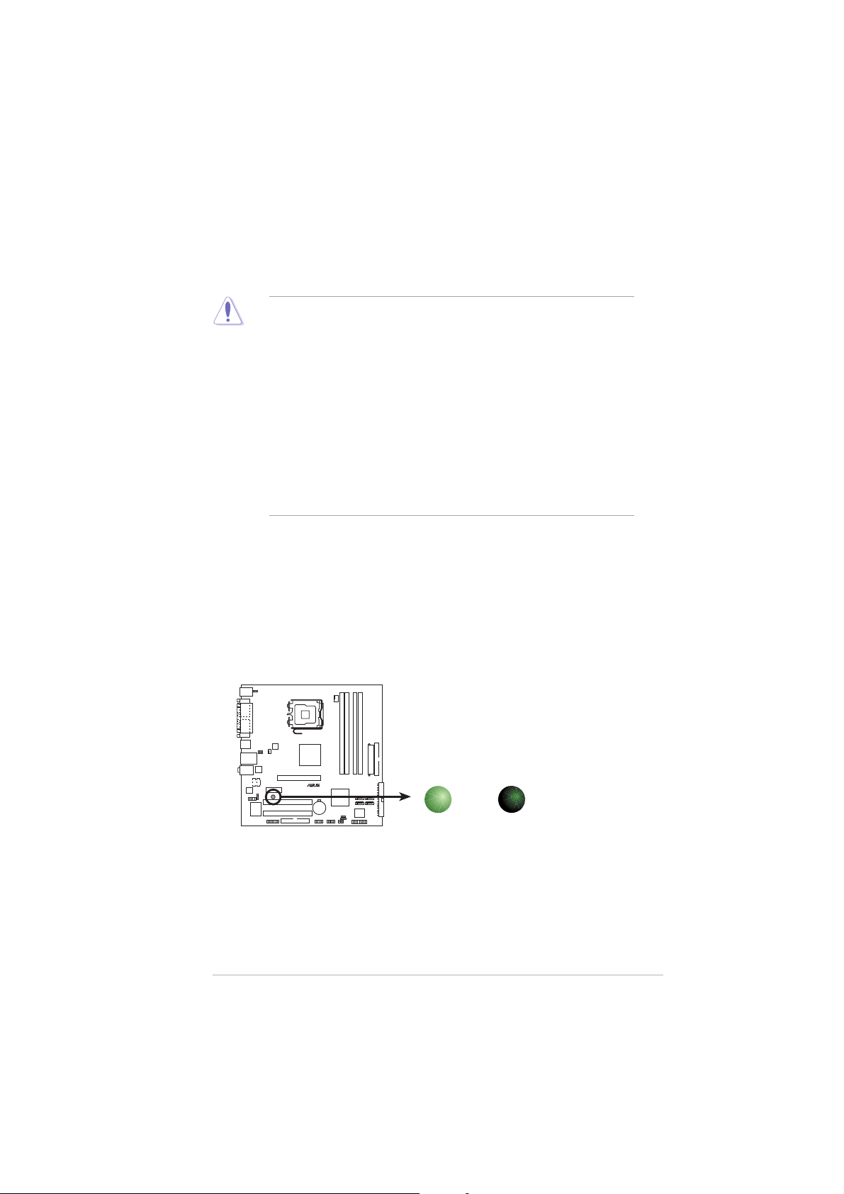
The motherboard comes with a standby power LED that lights up to
indicate that the system is ON, in sleep mode, or in soft-off mode.
This is a reminder that you should shut down the system and unplug
the power cable before removing or plugging in any motherboard
component. The illustration below shows the location of the onboard
LED.
P5VDC-MX Onboard LED
ASUS P5VDC-MXASUS P5VDC-MX
ASUS P5VDC-MX
ASUS P5VDC-MXASUS P5VDC-MX
P5VDC-MX
ON
Standby
Power
SB_PWR
OFF
Powere
Off
1-51-5
1-5
1-51-5
®
1.5 Motherboard overview
Before you install the motherboard, study the configuration of your chassis
to ensure that the motherboard fits into it.
Make sure to unplug the power cord before installing or removing the
motherboard. Failure to do so can cause you physical injury and damage
motherboard components.
1.5.11.5.1
1.5.1
1.5.11.5.1
Placement directionPlacement direction
Placement direction
Placement directionPlacement direction
When installing the motherboard, make sure that you place it into the
chassis in the correct orientation. The edge with external ports goes to the
rear part of the chassis as indicated in the image below.
1.5.21.5.2
1.5.2
1.5.21.5.2
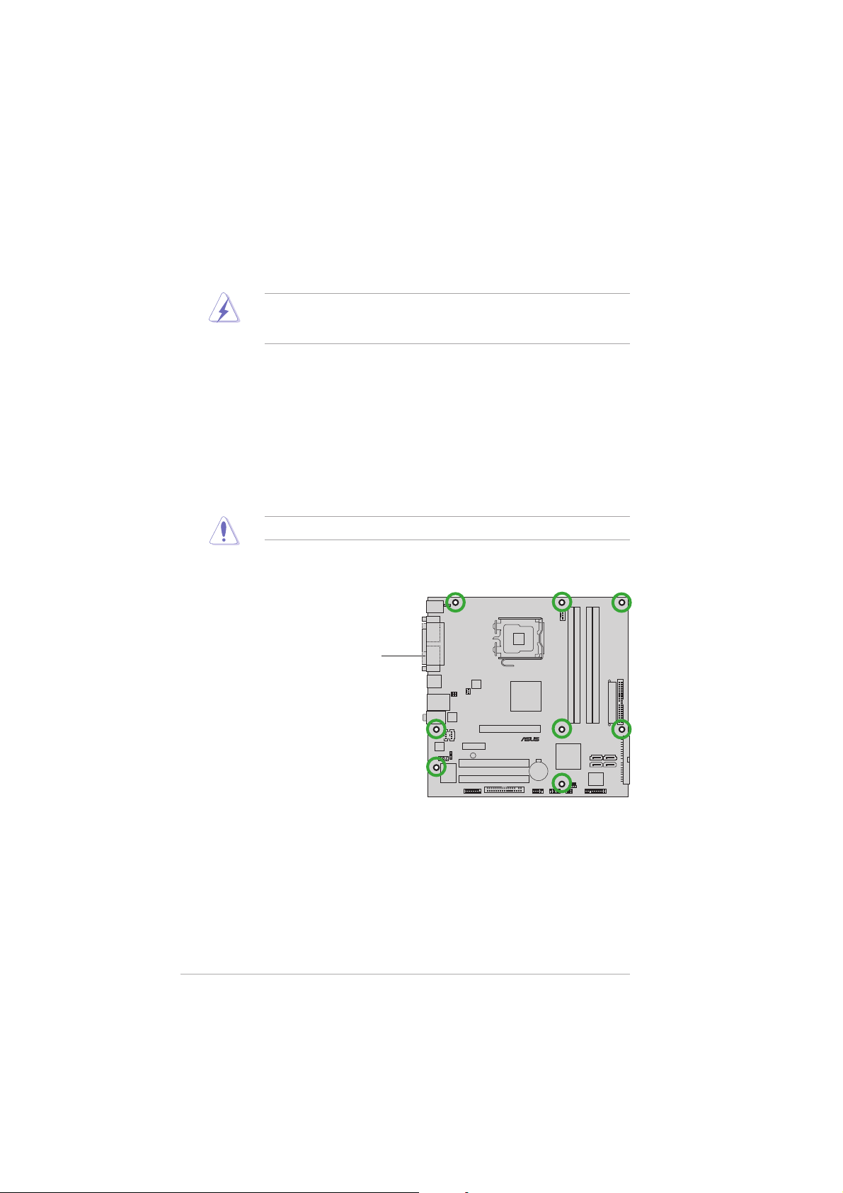
Screw holesScrew holes
Screw holes
Screw holesScrew holes
Place eight (8) screws into the holes indicated by circles to secure the
motherboard to the chassis.
Do not overtighten the screws! Doing so can damage the motherboard.
Place this side towardsPlace this side towards
Place this side towards
Place this side towardsPlace this side towards
the rear of the chassisthe rear of the chassis
the rear of the chassis
the rear of the chassisthe rear of the chassis
P5VDC-MX
1-61-6
1-6
1-61-6
Chapter 1: Product introductionChapter 1: Product introduction
Chapter 1: Product introduction
Chapter 1: Product introductionChapter 1: Product introduction
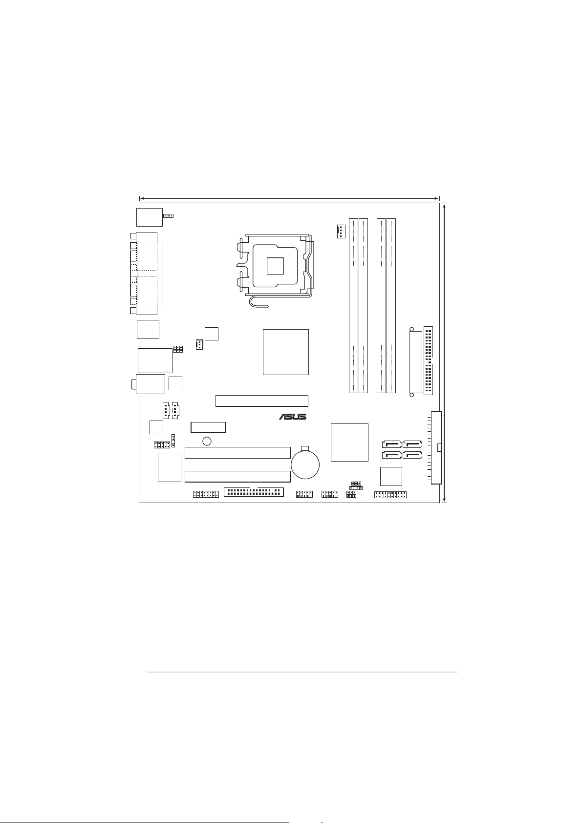
1.5.31.5.3
24.5cm (9.6in)
®
1.5.3
1.5.31.5.3
Motherboard layoutMotherboard layout
Motherboard layout
Motherboard layoutMotherboard layout
PS/2KBMS
T: Mouse
B: Keyboard
COM1
VGA
USB34
LAN_USB12
Top:Line In
Center:Line Out
Below:Mic In
ALC653
FP_AUDIO
KBPWR
PARALLEL PORT
USBPW12
USBPW34
RTL8201CL
Super
AUX1CD1
SPDIF_OUT
I/O
CHA_FAN
PCIEX1
GAME
ATX12V
SB_PWR
PCI1
PCI2
FLOPPY
LGA775
P4M800 PRO
AGP
VIA
CR2032 3V
Lithium Cell
CMOS Power
USB56
CPU_FAN
USB78
DDR2_2 (64 bit,240-pin module)
DDR2_1 (64 bit,240-pin module)
P5VDC-MX
VIA
VT8251
CLRTC
CHASSIS
USBPW56
USBPW78
PRI_IDE
DDR_2 (64 bit,184-pin module)
DDR_1 (64 bit,184-pin module)
EATXPWR
SATA1 SATA2
SATA3
SATA4
4Mb
BIOS
PANEL
SEC_IDE
24.5cm (9.6in)
ASUS P5VDC-MXASUS P5VDC-MX
ASUS P5VDC-MX
ASUS P5VDC-MXASUS P5VDC-MX
1-71-7
1-7
1-71-7
1.6 Central Processing Unit (CPU)
®
The motherboard comes with a surface mount LGA775 socket designed for
the Intel® Pentium® 4/Intel® Pentium® D processor in the 775-land package.
•
Your boxed Intel® Pentium® 4 LGA775 processor package should
come with installation instructions for the CPU, fan and heatsink
assembly. If the instructions in this section do not match the CPU
documentation, follow the latter.
• Upon purchase of the motherboard, make sure that the PnP cap is
on the socket and the socket pins are not bent. Contact your
retailer immediately if the PnP cap is missing, or if you see any
damage to the PnP cap/socket pins/motherboard components.
ASUS will shoulder the cost of repair only if the damage is shipment/
transit-related.
• Keep the cap after installing the motherboard. ASUS will process
Return Merchandise Authorization (RMA) requests only if the
motherboard comes with the cap on the LGA775 socket.
•
The product warranty does not cover damage to the socket pins
resulting from incorrect CPU installation/removal, or misplacement/
loss/incorrect removal of the PnP cap.
•
Due to chipset limitation.The motherboard does not support
Enhanced Intel SpeedStep technology, C1E and TM2 technology.
•
This motherboard does not support Intel® Pentium
Extreme Edition.
®
Processor
1.6.11.6.1
1.6.1
1.6.11.6.1
Installling the CPUInstallling the CPU
Installling the CPU
Installling the CPUInstallling the CPU
To install a CPU:
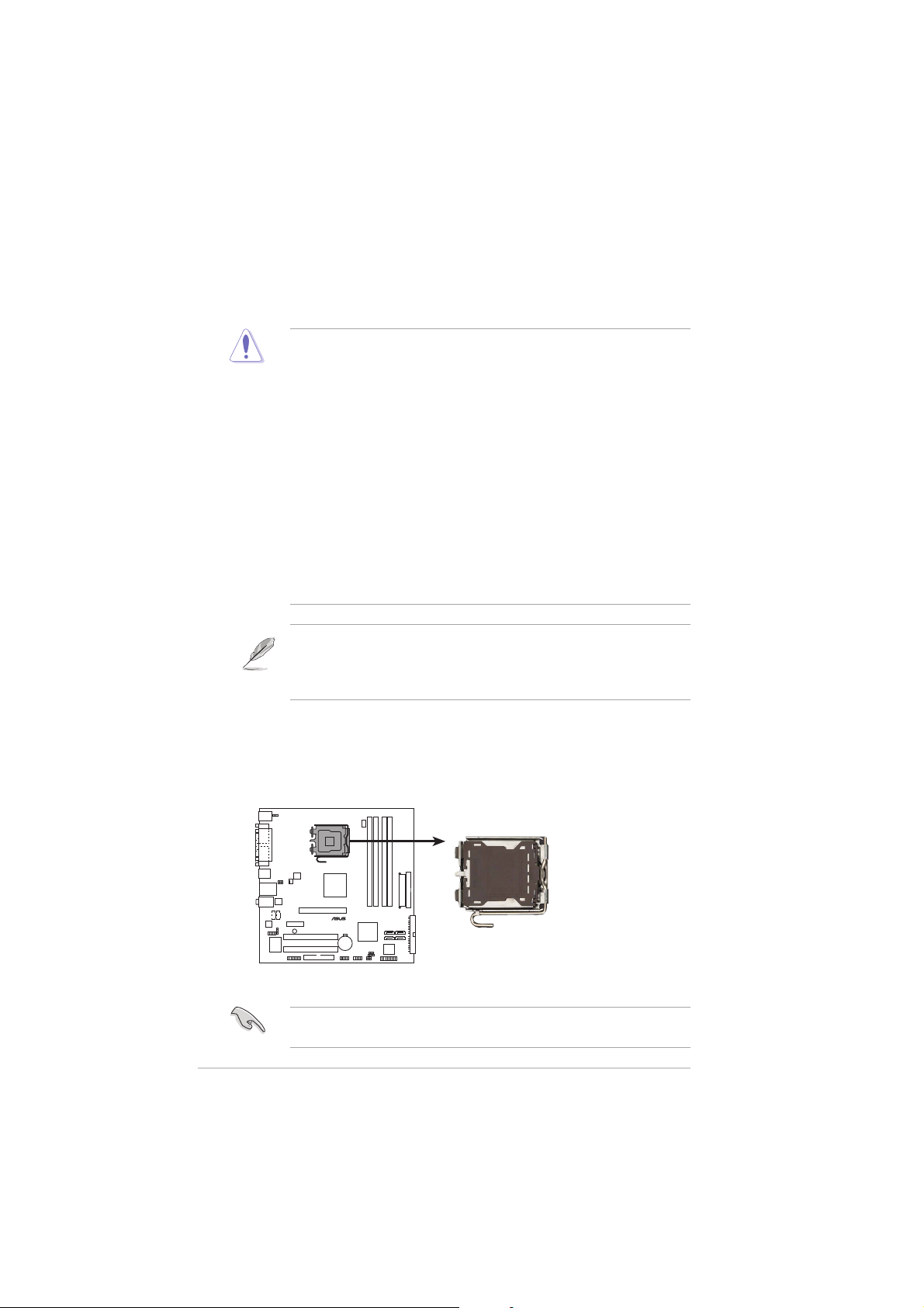
1. Locate the CPU socket on the motherboard.
P5VDC-MX
P5VDC-MX CPU Socket 775
Before installing the CPU, make sure that the socket box is facing
towards you and the load lever is on your left.
1-81-8
1-8
1-81-8
Chapter 1: Product introductionChapter 1: Product introduction
Chapter 1: Product introduction
Chapter 1: Product introductionChapter 1: Product introduction
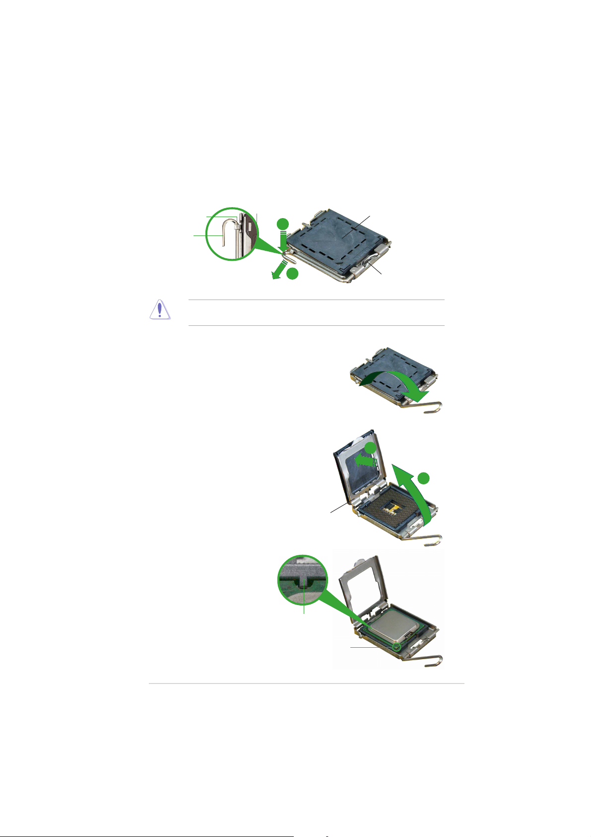
2. Press the load lever with your thumb (A) and move it to the left (B)
until it is released from the retention tab.
PnP CapPnP Cap
PnP Cap
Retention tabRetention tab
Retention tab
Retention tabRetention tab
Load leverLoad lever
Load lever
Load leverLoad lever
A
PnP CapPnP Cap
B
To prevent damage to the socket pins, do not remove the PnP cap
unless you are installing a CPU.
3. Lift the load lever in the direction
of the arrow to a 135º angle.
4. Lift the load plate with your
thumb and forefinger to a 100º
angle (A), then push the PnP cap
from the load plate window to
remove (B).
Load plateLoad plate
Load plate
Load plateLoad plate
This side of the camThis side of the cam
This side of the cam
This side of the camThis side of the cam
box should face you.box should face you.
box should face you.
box should face you.box should face you.
B
A
5. Position the CPU over the
socket, making sure that
the gold triangle is on
the bottom-left corner of
the socket. The socket
alignment key should fit
into the CPU notch.
ASUS P5VDC-MXASUS P5VDC-MX
ASUS P5VDC-MX
ASUS P5VDC-MXASUS P5VDC-MX
Alignment keyAlignment key
Alignment key
Alignment keyAlignment key
Gold triangle markGold triangle mark
Gold triangle mark
Gold triangle markGold triangle mark
1-91-9
1-9
1-91-9
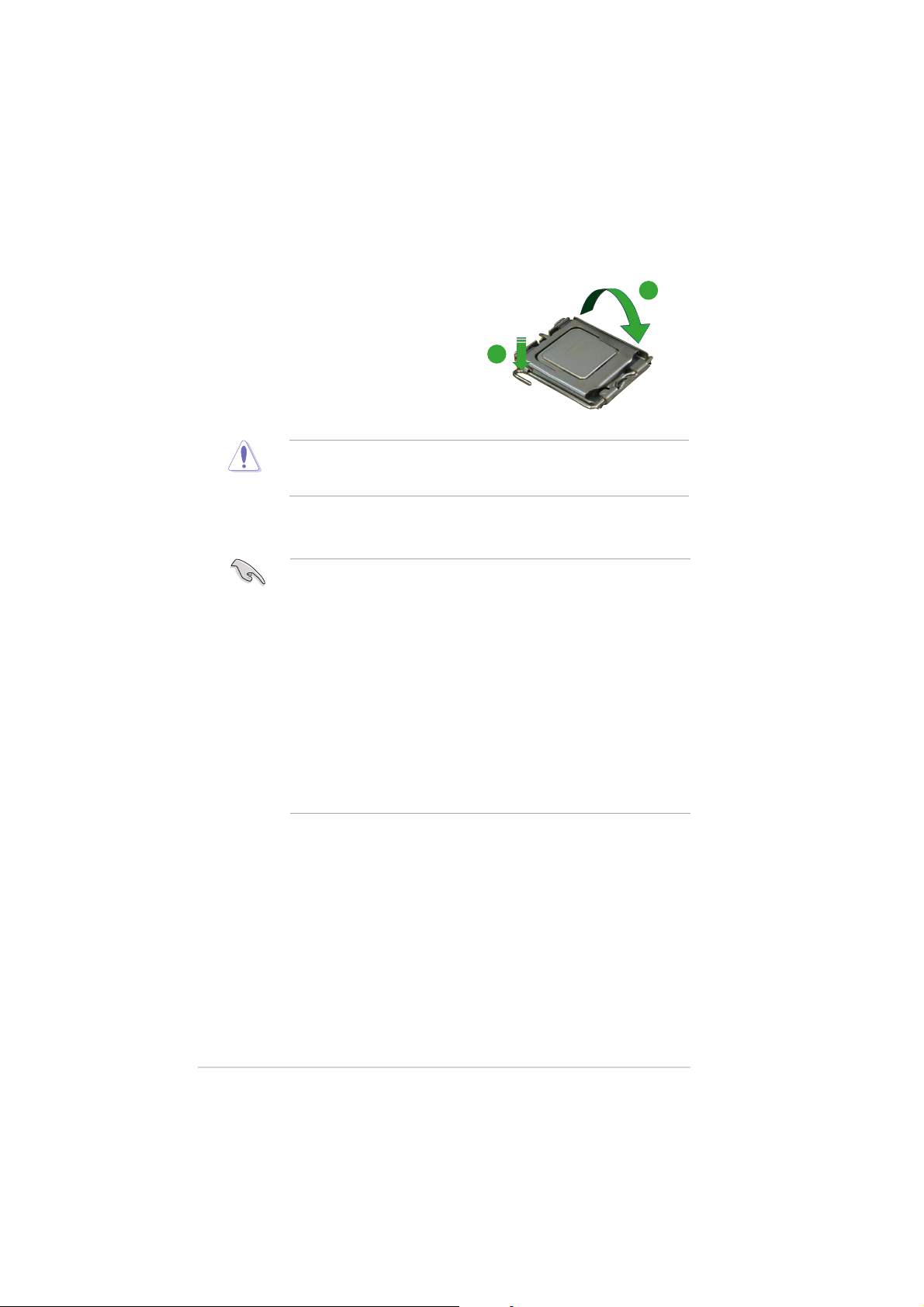
6. Close the load plate (A), then
push the load lever (B) until it
snaps into the retention tab.
The CPU fits in only one correct orientation. DO NOT force the CPU into
the socket to prevent bending the connectors on the socket and
damaging the CPU!
A
B
Notes on IntelNotes on Intel
Notes on Intel
Notes on IntelNotes on Intel
®
Hyper-Threading Technology Hyper-Threading Technology
Hyper-Threading Technology
Hyper-Threading Technology Hyper-Threading Technology
• This motherboard supports Intel® Pentium® 4 CPUs in the 775-land
package with Hyper-Threading Technology.
• Hyper-Threading Technology is supported under Windows® XP/2003
Server and Linux 1.7.x (kernel) and later versions only. Under Linux,
use the Hyper-Threading compiler to compile the code. If you are
using any other operating systems, disable the Hyper-Threading
Technology item in the BIOS to ensure system stability and
performance.
• Installing Windows® XP Service Pack 1 or later version is
recommended.
• Make sure to enable the Hyper-Threading Technology item in BIOS
before installing a supported operating system.
• For more information on Hyper-Threading Technology, visit
www.intel.com/info/hyperthreading.
To use the Hyper-Threading Technology on this motherboard:
®
1. Install an Intel
Pentium® 4 CPU in the 775-land package that supports
Hyper-Threading Technology.
2. Power up the system and enter the BIOS Setup (see Chapter 2: BIOS
setup). Under the Advanced Menu, make sure that the item
Hyper-Threading Technology is set to Enabled. The item appears only
if you installed a CPU that supports Hyper-Threading Technology.
3. Reboot the computer.
1-101-10
1-10
1-101-10
Chapter 1: Product introductionChapter 1: Product introduction
Chapter 1: Product introduction
Chapter 1: Product introductionChapter 1: Product introduction
1.6.21.6.2
1.6.2
1.6.21.6.2
Installling the CPU heatsink and fanInstallling the CPU heatsink and fan
Installling the CPU heatsink and fan
Installling the CPU heatsink and fanInstallling the CPU heatsink and fan
The Intel® Pentium® 4/Pentium® D LGA775 processor requires a specially
designed heatsink and fan assembly to ensure optimum thermal condition
and performance.
• Install the motherboard to the chassis before you install the CPU fan
and heatsink assembly
• When you buy a boxed Intel® Pentium® 4 processor, the package
includes the CPU fan and heatsink assembly. If you buy a CPU
separately, make sure that you use only Intel®-certified
multi-directional heatsink and fan.
• Your Intel® Pentium® 4 LGA775 heatsink and fan assembly comes in
a push-pin design and requires no tool to install.
If you purchased a separate CPU heatsink and fan assembly, make sure
that a Thermal Interface Material is properly applied to the CPU heatsink
or CPU before you install the heatsink and fan assembly.
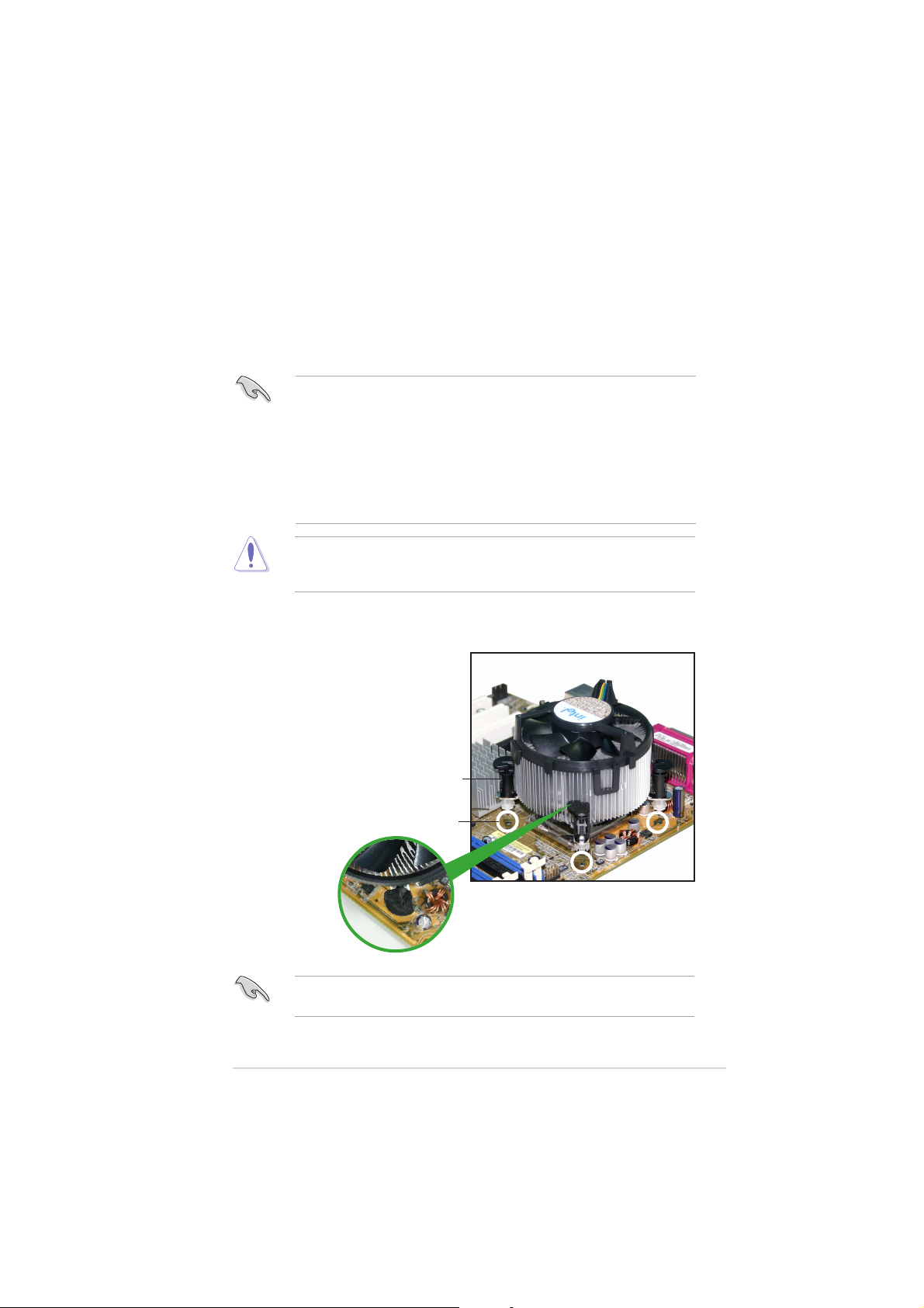
To install the CPU heatsink and fan:
1. Place the heatsink on top of the
installed CPU, making sure that
the four fasteners match the
holes on the motherboard.
Make sure each fastener is oriented as shown, with the narrow groove
directed outward.
ASUS P5VDC-MXASUS P5VDC-MX
ASUS P5VDC-MX
ASUS P5VDC-MXASUS P5VDC-MX
FastenerFastener
Fastener
FastenerFastener
Motherboard holeMotherboard hole
Motherboard hole
Motherboard holeMotherboard hole
1-111-11
1-11
1-111-11
®
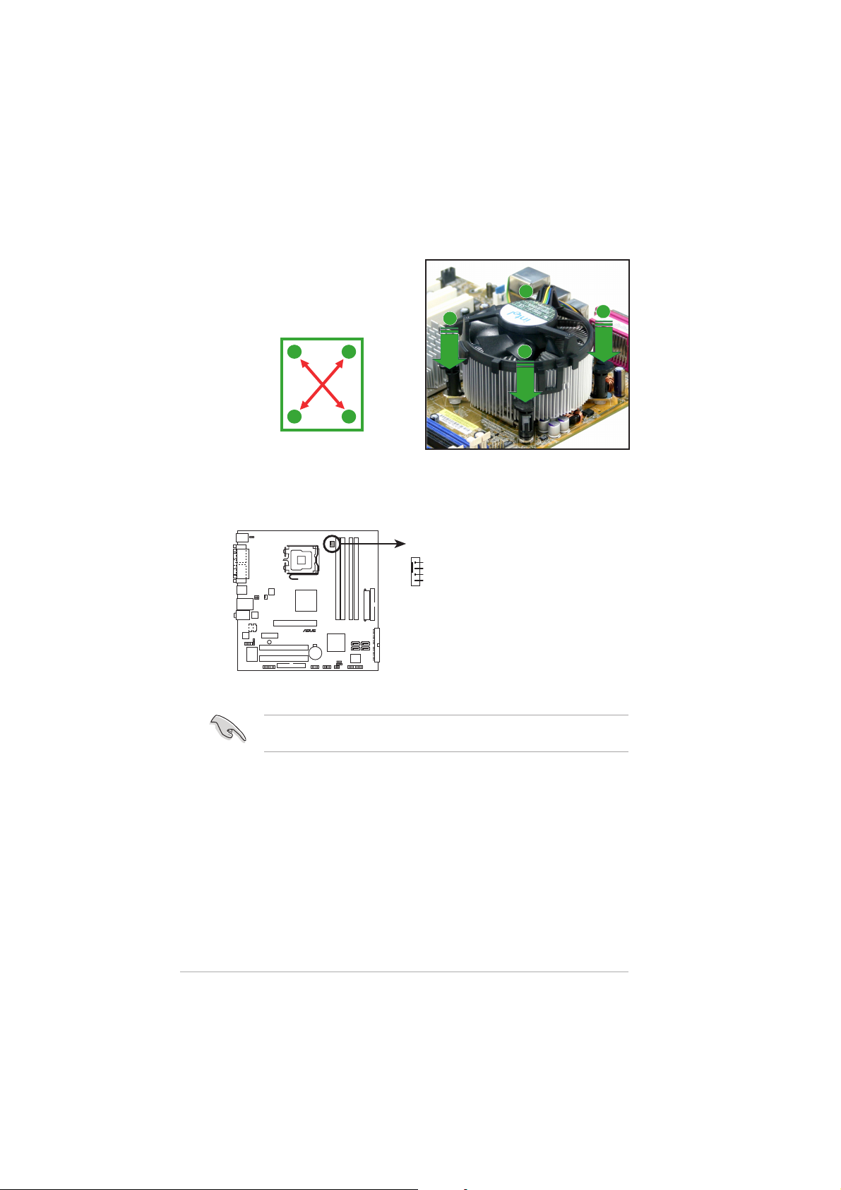
2. Push down two fasteners at a
time in a diagonal sequence to
secure the heatsink and fan
assembly in place.
B
A
A
A
B
B
A
B
3. When the fan and heatsink assembly is in place, connect the CPU fan
cable to the connector on the motherboard labeled CPU_FAN.
CPU_FAN
GND
CPU FAN PWR
CPU FAN IN
CPU FAN PWM
P5VDC-MX
P5VDC-MX CPU fan connector
Do not forget to connect the CPU fan connector! Hardware monitoring
errors can occur if you fail to plug this connector.
1-121-12
1-12
1-121-12
Chapter 1: Product introductionChapter 1: Product introduction
Chapter 1: Product introduction
Chapter 1: Product introductionChapter 1: Product introduction
1.6.31.6.3
1.6.3
1.6.31.6.3
Uninstalling the CPU heatsink and fanUninstalling the CPU heatsink and fan
Uninstalling the CPU heatsink and fan
Uninstalling the CPU heatsink and fanUninstalling the CPU heatsink and fan
To uninstall the CPU heatsink and fan:
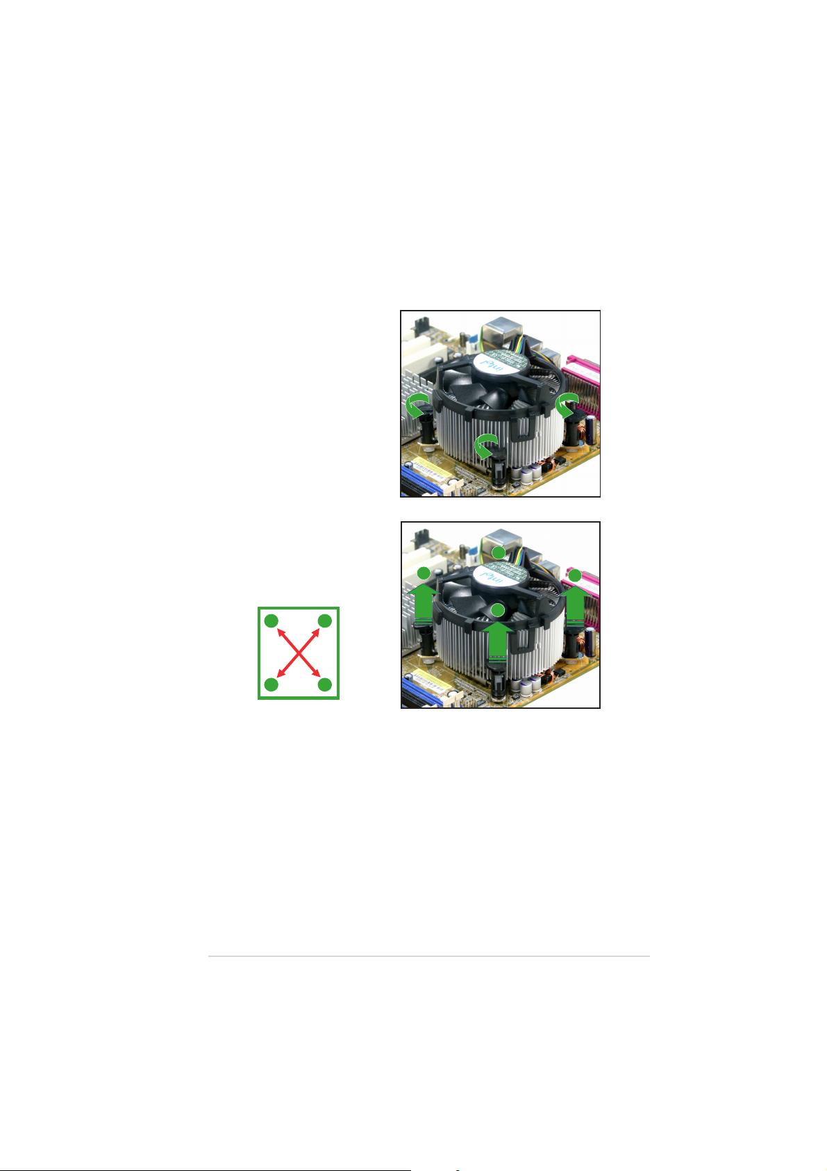
1. Disconnect the CPU fan
cable from the connector
on the motherboard labeled
CPU_FAN.
2. Rotate each fastener
counterclockwise.
3. Pull up two fasteners at a
time in a diagonal sequence
to disengage the heatsink
and fan assembly from the
A
motherboard.
A
B
B
A
B
B
ASUS P5VDC-MXASUS P5VDC-MX
ASUS P5VDC-MX
ASUS P5VDC-MXASUS P5VDC-MX
A
1-131-13
1-13
1-131-13
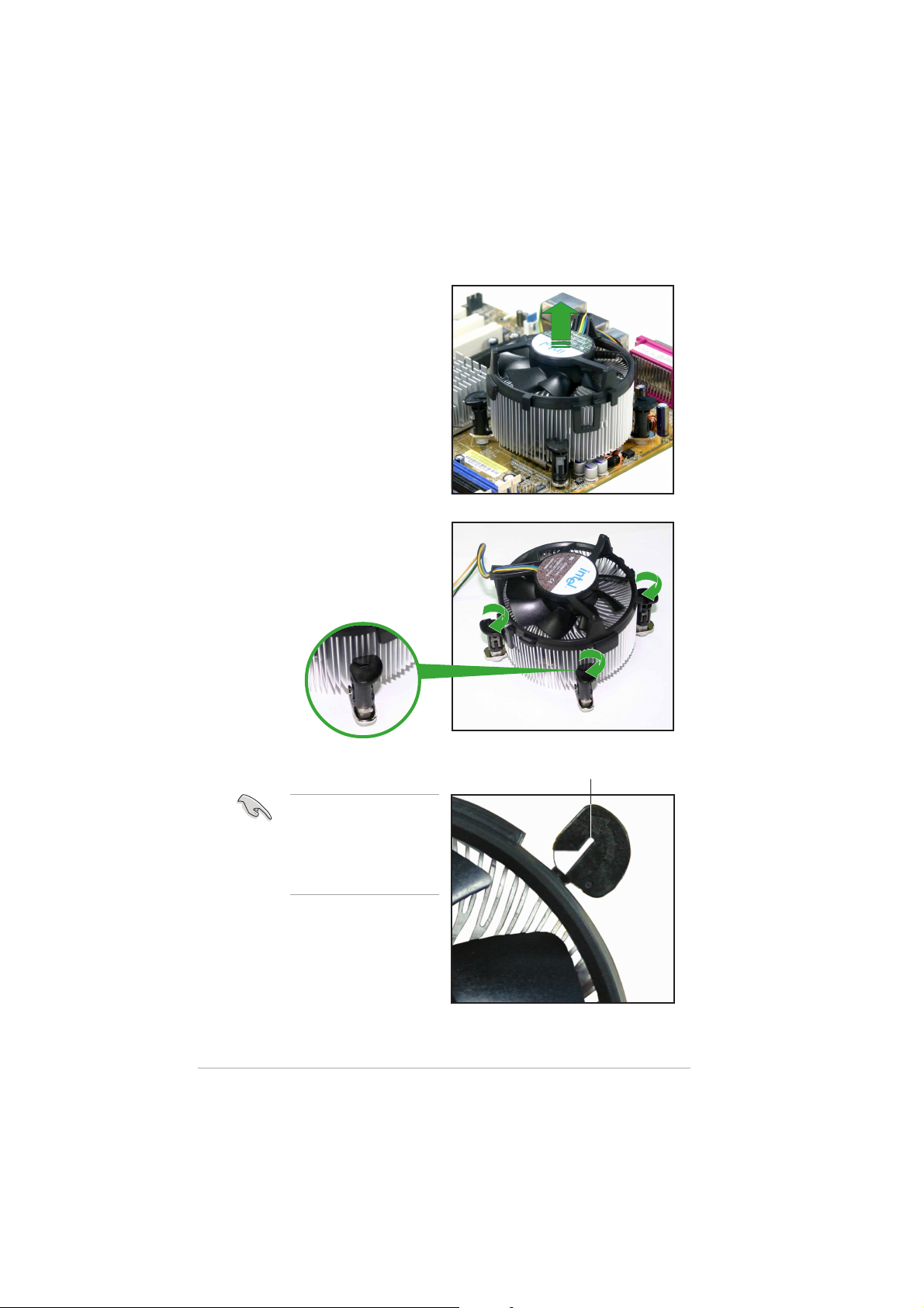
4. Remove the heatsink and fan
assembly from the
motherboard.
5. Rotate each fastener
clockwise to reset the
orientation.
1-141-14
1-14
1-141-14
The narrow end of the
groove should point
outward after resetting.
(The photo shows the
groove shaded for
emphasis.)
Narrow end of the grooveNarrow end of the groove
Narrow end of the groove
Narrow end of the grooveNarrow end of the groove
Chapter 1: Product introductionChapter 1: Product introduction
Chapter 1: Product introduction
Chapter 1: Product introductionChapter 1: Product introduction
1.7 System memory
®
2
2
1.7.11.7.1
1.7.1
1.7.11.7.1
OverviewOverview
Overview
OverviewOverview
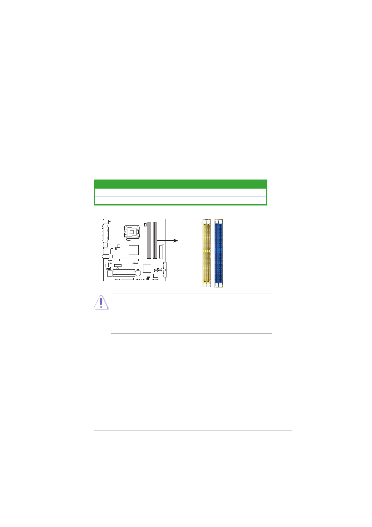
The motherboard comes with two 240-pin Double Data Rate (DDR2) and
two 184-pin DDR Dual Inline Memory Modules (DIMM) sockets.
DDR2 DIMMS are notched differently to prevent installation on a DDR DIMM
socket.
The following figure illustrates the location of the sockets:
ColorColor
Color
ColorColor
Blue DDR_1 and DDR_2
Yellow DDR2_1 and DDR2_2
P5VDC-MX
P5VDC-MX DDR DIMM sockets
• To prevent damage to the motherboard,
DDR2 memory simultaneously.DDR2 memory simultaneously.
DDR2 memory simultaneously.
DDR2 memory simultaneously.DDR2 memory simultaneously.
SocketsSockets
Sockets
SocketsSockets
DDR2_1DDR2_
DDR_1DDR_
do not use DDR anddo not use DDR and
do not use DDR and
do not use DDR anddo not use DDR and
• Due to chipset resource allocation, the system may detect less than
2 GB system memory when you installed two 1 GB DDR2 or DDR
memory modules.
1.7.21.7.2
1.7.2
1.7.21.7.2
Memory ConfigurationsMemory Configurations
Memory Configurations
Memory ConfigurationsMemory Configurations
You may install 256MB, 512MB, and 1 GB unbuffered non-ECC DDR/DDR2
DIMMs into the DIMM sockets.
ASUS P5VDC-MXASUS P5VDC-MX
ASUS P5VDC-MX
ASUS P5VDC-MXASUS P5VDC-MX
1-151-15
1-15
1-151-15

1.7.31.7.3
1.7.3
1.7.31.7.3
DDR Qualified Vendors ListDDR Qualified Vendors List
DDR Qualified Vendors List
DDR Qualified Vendors ListDDR Qualified Vendors List
Visit the ASUS website (www.asus.com) for the latest DDR DIMM modules
for this motherboard.
DDR2-533 Qualified Vendors ListDDR2-533 Qualified Vendors List
DDR2-533 Qualified Vendors List
DDR2-533 Qualified Vendors ListDDR2-533 Qualified Vendors List
DIMM support DIMM support
DIMM support
SizeSize
Vendor Vendor
Size
Vendor
SizeSize
Vendor Vendor
256MB KINGSTON E5116AB-5C-E N/A SS KVR533D2N4/256 V V
512MB KINGSTON HY5PS56821F-C4 N/A DS KVR533D2N4/512 V V
1024MB KINGSTON D6408TE7BL-37 N/A DS KVR533D2N4/1G V V
512MB SAMSUNG K4T51083QB-GCD5 N/A SS M378T6553BG0-CD5 V V
256MB SAMSUNG K4T56083QF-GCD5 N/A SS M378T3253FG0-CD5 V V
512MB SAMSUNG K4T56083QF-GCD5 N/A DS M378T6453FG0-CD5 V V
1024MB SAMSUNG K4T51083QB-GCD5 N/A DS M378T2953BG0-CD5 V V
512MB MICRON 4FBIID9BQM N/A DS MT16HTF6464AG-53EB2 V
256MB MICRON 4DBIIZ9BQT N/A SS N/A V V
256MB MICRON 4FBIID9CHM N/A SS MT8HTF3264AY-53EB3 V V
512MB MICRON 4FBIID9CHM N/A DS MT16HTF6464AY-53EB2 V V
512MB Infineon HYB18T512800AC37 N/A SS HYS64T64000GU-3.7-A V V
256MB Infineon HYB18T512160AF-3.7 N/A SS HYS64T32000HU-3.7-A V V
512MB Infineon HYB18T512800AF37 N/A SS HYS64T64000HU-3.7-A V V
256MB Infineon HYB18T512800AF37 N/A DS HYS64T128020HU-3.7-A V V
256MB Infineon HYB18T5121608BF-3.7 N/A SS HYS64T32000HU-3.7-B V V
512MB Infineon HYB18T512800BF37 N/A SS HYS64T64000HU-3.7-B V V
1024MB Infineon HYB18T512800BF37 N/A DS HYS64T128020HU-3.7-B V V
512MB Hynix HY5PS12821F-C4 N/A SS HYMP564U648-C4 V V
1024MB Hynix HY5PS12821F-C4 N/A DS HYMP512U648-C4 V V
1024MB Hynix HY5PS12821FP-C4 N/A DS HYMP512U648-C4 V V
512MB Hynix HY5PS12821AFP-C3 N/A SS HYMP564U64AP8-C3 V V
1024MB Hynix HY5PS12821AFP-C3 N/A DS HYMP512U64AP8-C3 V V
512MB ELPIDA E5108AB-5C-E N/A SS EBE51UD8ABFA-5C V V
512MB ELPIDA E5108AB-5C-E N/A SS EBE51UD8ABFA-5C-E V V
1024MB ELPIDA E5108AB-5C-E N/A DS EBE11UD8ABFA-5C-E V V
2048MB ELPIDA E1108AA-5C-E N/A DS EBE21EE8AAFA-5C-E V
256MB CORSAIR MIII0051832M8CEC N/A SS VS256MB533D2 V V
512MB CORSAIR MI110052432M8CEC N/A DS VS512MB533D2 V V
256MB Apacer E5116AB-5C-E N/A SS 78.81077.420 V V
256MB crucial Heat-Sink Package N/A SS BL3264AA53V.8FB V V
512MB crucial Heat-Sink Package N/A DS BL6464AA53V.16FB V V
256MB KINGMAX K4T56083QF-GCD5 N/A SS KLBB68K-38SP4 V V
1024MB KINGMAX E5108AB-5C-E N/A DS KLBD48F-A8EP4 V V
512MB KINGMAX E5108AB-5C-E N/A SS KLBC28F-A8EP4 V
512MB KINGMAX KKEA88A4IA-37 N/A SS KLBC28F-A8KP4 V V
256MB KINGMAX E5116AB-5C-E N/A SS KLBB68F-36EP4 V V
512MB KINGMAX E5108AE-5C-E N/A SS KLBC28F-A8EB4 V V
512MB Transcend K4T51083QB-GCD5 N/A SS TS64MLQ64V5J V
1024MB Transcend K4T51083QB-GCD5 N/A DS TS128MLQ64V5J V V
Model Model
Model
Model Model
Brand Side(s) ComponentBrand Side(s) Component
Brand Side(s) Component
Brand Side(s) ComponentBrand Side(s) Component
DIMM support DIMM support
AA
BB
A
B
AA
BB
Legend:Legend:
Legend:
Legend:Legend:
A A
A - supports one module inserted in any
A A
BB
B - supports one pair of modules inserted into both of the
BB
SSSS
S S - Single-sided
SSSS
DSDS
D S - Double-sided
DSDS
1-161-16
1-16
1-161-16
yellowyellow
yellow slot.
yellowyellow
yellowyellow
yellow slots.
yellowyellow
Chapter 1: Product introductionChapter 1: Product introduction
Chapter 1: Product introduction
Chapter 1: Product introductionChapter 1: Product introduction

DDR400 Qualified Vendors ListDDR400 Qualified Vendors List
DDR400 Qualified Vendors List
DDR400 Qualified Vendors ListDDR400 Qualified Vendors List
DIMM support DIMM support
DIMM support
SizeSize
Size
SizeSize
512MB KINGSTON Heat-Sink Package N/A DS KHX3200A/512 V V
256MB KINGSTON D3208DL3T-5A N/A SS KVR400X64C3A/256 V V
256MB KINGSTON A2S56D30BTP N/A SS KVR400X64C3A/256 V
512MB KINGSTON V58C2256804SAT5 N/A DS KVR400X64C3A/512 V V
512MB KINGSTON HY5DU12822BT-D43 N/A SS KVR400X64C3A/512 V V
1024MB KINGSTON HYB25D512800BE-5B N/A DS KVR400X64C3A/1G V V
256MB SAMSUNG K4H560838E-TCCC SAMSUNG SS M368L3223ETM-CCC V V
256MB SAMSUNG K4H560838F-TCCC SAMSUNG SS M368L3223FTN-CCC V
512MB SAMSUNG K4H560838F-TCCC SAMSUNG DS M368L6423FTN-CCC V V
512MB SAMSUNG K4H510838B-TCCC SAMSUNG SS M368L6523BTM-CCC V V
256MB MICRON MT46V32M8TG-5BC MICRON SS MT8VDDT3264AG-40BCB V
512MB MICRON MT46V32M8TG-5BC MICRON DS MT16VDDT6464AG-40BCB V V
256MB Infineon HYB25D256800CE-5C Infineon SS HYS64D32300HU-5-C V V
512MB Infineon HYB25D256800CE-5C Infineon DS HYS64D64320HU-5-C V V
256MB Infineon HYB25D512160CE-5C Infineon SS HYS64D32301HU-5-C V V
512MB Infineon HYB25D512800CE-5C Infineon SS HYS64D64300HU-5-C V
1024MB Infineon HYB25D512800CE-5B Infineon DS HYS64D128320HU-5-C V V
256MB CORSAIR W942508BH-5 N/A SS CMX256A-3200C2PT V V
512MB CORSAIR Heat-Sink Package N/A DS CMX512-3200C2 V V
512MB CORSAIR VS32M8-5 N/A DS VS512MB400 V V
512MB CORSAIR Heat-Sink Package N/A DS CMXP512-3200XL V
1024MB CORSAIR Heat-Sink Package N/A DS TWINX2048-3200C2 V V
256MB Hynix HY5DU56822DT-D43 N/A SS HYMD232646D8J-D43 V V
512MB Hynix HY5DU56822DT-D43 N/A DS HYMD264646D8J-D43 V
256MB Transcend K4H560838F-TCCC SAMSUNG SS TS32MLD64V4F3 V V
512MB Transcend K4H560838F-TCCC SAMSUNG DS TS64MLD64V4F3 V
1024MB Transcend K4H510838B-TCCC SAMSUNG DS TS128MLD64V4J V V
256MB A DATA K4H560838E-TCCC SAMSUNG SS MDOSS6F3G31Y0K1E0Z V V
512MB A DATA K4H560838F-TCCC SAMSUNG DS MDOSS6F3H41Y0N1E0Z V V
256MB A DATA HY5DU56822CT-D43 Hynix SS MDOHY6F3G31Y0N1E0Z V V
512MB A DATA HY5DU56822CT-D43 Hynix DS MDOHY6F3H41Y0N1E0Z V V
256MB A DATA ADD8608A8A-5B N/A SS MDOAD5F3G31Y0D1E02 V
512MB A DATA ADD8608A8A-5B N/A DS MDOAD5F3H41Y0D1E02 V
256MB KINGMAX KDL388P4LA-50 N/A SS MPXB62D-38KT3R V V
256MB crucial Heat-Sink Package Ballistix SS BL3264Z402.8TG V V
VendorVendor
Vendor
VendorVendor
ModelModel
Model
ModelModel
BrandBrand
Brand
BrandBrand
Side(s)Side(s)
Side(s)
Side(s)Side(s)
DIMM support DIMM support
ComponentComponent
Component
ComponentComponent
AA
BB
A
B
AA
BB
Legend:Legend:
Legend:
Legend:Legend:
A A
A - supports one module inserted in any
A A
BB
B - supports one pair of modules inserted into both of the
BB
SSSS
S S - Single-sided
SSSS
DSDS
D S - Double-sided
DSDS
ASUS P5VDC-MXASUS P5VDC-MX
ASUS P5VDC-MX
ASUS P5VDC-MXASUS P5VDC-MX
blueblue
blue slot.
blueblue
blueblue
blue slots.
blueblue
1-171-17
1-17
1-171-17
 Loading...