

Page 1

R
AP7500
Pentium® II Corporate Server
Hardware Reference Guide
Page 2

User’s Notice
No part of this manual, including the products and software described in it, may be
reproduced, transmitted, transcribed, stored in a retrieval system, or translated into
any language in any form or by any means, except documentation kept by the purchaser for backup purposes, without the express written permission of ASUSTeK
COMPUTER INC. (“ASUS”).
ASUS PROVIDES THIS MANUAL “AS IS” WITHOUT WARRANTY OF ANY
KIND, EITHER EXPRESS OR IMPLIED, INCLUDING BUT NOT LIMITED
TO THE IMPLIED WARRANTIES OR CONDITIONS OF MERCHANTABILITY OR FITNESS FOR A PARTICULAR PURPOSE. IN NO EVENT SHALL
ASUS, ITS DIRECTORS, OFFICERS, EMPLOYEES OR AGENTS BE LIABLE
FOR ANY INDIRECT , SPECIAL, INCIDENT AL, OR CONSEQUENTIAL DAMAGES (INCLUDING DAMAGES FOR LOSS OF PROFITS, LOSS OF BUSINESS, LOSS OF USE OR DATA, INTERRUPTION OF BUSINESS AND THE
LIKE), EVEN IF ASUS HAS BEEN ADVISED OF THE POSSIBILITY OF SUCH
DAMAGES ARISING FROM ANY DEFECT OR ERROR IN THIS MANUAL
OR PRODUCT.
Product warranty or service will not be extended if: (1) the product is repaired,
modified or altered, unless such repair, modification of alteration is authorized in
writing by ASUS; or (2) the serial number of the product is defaced or missing.
Products and corporate names appearing in this manual may or may not be registered trademarks or copyrights of their respective companies, and are used only for
identification or explanation and to the owners’ benefit, without intent to infringe.
• Intel, LANDesk, and Pentium are registered trademarks of Intel Corporation.
• IBM and OS/2 are registered trademarks of International Business Machines.
• MS-DOS, W indows, W indowsNT are registered trademarks of Microsoft Corporation.
• Adobe and Acrobat are registered trademarks of Adobe Systems Incorporated.
The product name and revision number are both printed on the product itself. Manual
revisions are released for each product design represented by the digit before and
after the period of the manual revision number . Manual updates are represented by
the third digit in the manual revision number.
For previous or updated manuals, BIOS, drivers, or product release information,
contact ASUS at http://www.asus.com.tw or through any of the means indicated on
the following page.
SPECIFICA TIONS AND INFORMA TION CONTAINED IN THIS MANUAL ARE
FURNISHED FOR INFORMATIONAL USE ONLY, AND ARE SUBJECT TO
CHANGE AT ANY TIME WITHOUT NOTICE, AND SHOULD NOT BE CONSTRUED AS A COMMITMENT BY ASUS. ASUS ASSUMES NO RESPONSIBILITY OR LIABILITY FOR ANY ERRORS OR INACCURACIES THAT MA Y
APPEAR IN THIS MANUAL, INCLUDING THE PRODUCTS AND SOFTWARE
DESCRIBED IN IT.
Copyright © 1998 ASUSTeK COMPUTER INC. All Rights Reserved.
Product Name: AP7500
Manual Revision: 1.00 E280
Release Date: September 1998
2
AP7500 Hardware Reference Guide
Page 3

ASUS Contact Information
ASUSTeK COMPUTER INC.
Marketing
Address: 150 Li-Te Road, Peitou, Taipei, Taiwan 112
Telephone: +886-2-2894-3447
Fax: +886-2-2894-3449
Email: [email protected]
Technical Support
Fax: +886-2-2895-9254
BBS: +886-2-2896-4667
Email: [email protected]
WWW: www.asus.com.tw
FTP: ftp.asus.com.tw/pub/ASUS
ASUS COMPUTER INTERNATIONAL
Marketing
Address: 6737 Mowry Avenue, Mowry Business Center, Building 2
Technical Support
Fax: +1-510-608-4555
BBS: +1-510-739-3774
Email: [email protected]
WWW: www.asus.com
FTP: ftp.asus.com.tw/pub/ASUS
ASUS COMPUTER GmbH
Marketing
Address: Harkort Str. 25, 40880 Ratingen, BRD, Germany
Telephone: 49-2102-445011
Fax: 49-2102-442066
Email: [email protected]
Technical Support
Hotline: 49-2102-499712
BBS: 49-2102-448690
Email: [email protected]
WWW: www.asuscom.de
FTP: ftp.asuscom.de/pub/ASUSCOM
AP7500 Hardware Reference Guide 3
Page 4

Contents
I. Introduction .............................................................7
This Reference Guide ............................................................. 7
Sections .............................................................................. 7
Symbols .............................................................................. 7
This Server .............................................................................. 8
Component Checklist .............................................................. 8
Features .................................................................................. 9
Safety and Warning............................................................... 10
Static-Sensitive Devices ................................................... 10
Tools Required .......................................................................11
Preparation.............................................................................11
II. System Components ...........................................12
Server Front Side .................................................................. 12
Server Back Side................................................................... 13
Chassis Security ............................................................... 13
Chassis Panels ................................................................. 14
Circulation System............................................................ 15
Fan Replacement ............................................................. 15
Fixed Storage Device Tray .................................................... 16
Fixed Device Bay Cover Clips .......................................... 16
Fixed Device Bay Cover ................................................... 16
Fixed Storage Devices .......................................................... 17
Floppy Drive and CD-ROM............................................... 17
Floppy Drive and Storage Device Spacers....................... 17
Hot-Swap Trays..................................................................... 18
Hot-Swap Tray Interface........................................................ 18
Hot-Swap Tray Usage ........................................................... 19
Hot-Swap Tray Front Connections.................................... 19
Hot-Swap Tray Connector Board .......................................... 20
Hot-Swap Tray Rear Connections .................................... 20
Motherboard Securing ...................................................... 21
Spacer Mounts.................................................................. 21
SCSI Backplane .................................................................... 22
SCSI Board Placement..................................................... 22
SCSI ID Setting................................................................. 23
SCSI ID Dip Switches ....................................................... 23
4
AP7500 Hardware Reference Guide
Page 5

Contents
SCSI Information ................................................................... 24
SCSI Connections ............................................................ 24
SCSI Termination .............................................................. 24
SCSI ID Jumpers .............................................................. 24
SCSI ID Priority................................................................. 24
Device Cables ....................................................................... 25
Cable Connections ........................................................... 25
Device Connections.......................................................... 26
Floppy Disk Drive (1.44MB).............................................. 27
IDE Cabling....................................................................... 27
CD-ROM Disk Drive (IDE) ................................................ 27
Ultra2 SCSI Disk Drive ..................................................... 28
External Ultra2 SCSI Terminator....................................... 28
Expansion Cards ................................................................... 28
Power Supply ........................................................................ 30
Power Supply Mounting.................................................... 30
Power Module Rating ....................................................... 31
Power Module Failure....................................................... 31
Starting the Server ................................................................ 32
LED Indicators....................................................................... 32
III. Appendix ..............................................................33
SCSI Cable Limits ................................................................. 33
Power Supply Information ..................................................... 34
Input Voltage ..................................................................... 34
Input Current..................................................................... 34
Output Current Capacity ................................................... 34
Output Voltage Regulation, Ripple, and Noise ................. 34
Regulatory Information .......................................................... 34
Safety................................................................................ 34
EMI ................................................................................... 34
Power Supply Requirement Calculation Table ...................... 35
Glossary ................................................................................ 36
AP7500 Hardware Reference Guide 5
Page 6
FCC & DOC Compliance
Federal Communications Commission Statement
This device complies with FCC Rules Part 15. Operation is subject to the
following two conditions:
• This device may not cause harmful interference, and
• This device must accept any interference received, including interference that may cause undesired operation.
This equipment has been tested and found to comply with the limits for a
Class B digital device, pursuant to Part 15 of the FCC Rules. These limits
are designed to provide reasonable protection against harmful interference
in a residential installation. This equipment generates, uses and can radiate
radio frequency energy and, if not installed and used in accordance with
manufacturer’s instructions, may cause harmful interference to radio communications. However, there is no guarantee that interference will not occur in a particular installation. If this equipment does cause harmful interference to radio or television reception, which can be determined by turning the equipment off and on, the user is encouraged to try to correct the
interference by one or more of the following measures:
• Reorient or relocate the receiving antenna.
• Increase the separation between the equipment and receiver.
• Connect the equipment to an outlet on a circuit different from that to
which the receiver is connected.
• Consult the dealer or an experienced radio/TV technician for help.
IMPORTANT! The use of shielded cables for connection of the moni-
tor to the graphics card is required to assure compliance with FCC regulations. Changes or modifications to this unit not expressly approved
by the party responsible for compliance could void the user’s authority
to operate this equipment.
Canadian Department of Communications Statement
This digital apparatus does not exceed the Class B limits for radio noise
emissions from digital apparatus set out in the Radio Interference Regulations of the Canadian Department of Communications.
6
AP7500 Hardware Reference Guide
Page 7
I. Introduction
This Reference Guide
You are reading the AP7500 Hardware Reference Guide. This hardware
reference guide provides information and procedures on the various components used in this server . Some components shown in this reference guide
are optional and may be individually purchased to complete this server.
This guide is intended for experienced users and integrators with hardware
knowledge of personal computers. You should also read all documentation
and manuals included with this server and with your separately purchased
components.
Sections
There are only a few sections in this reference guide as follows:
I. Introduction
This section gives general and startup information and features for this server .
I. Introduction
Sections / Symbols
II. Components
This is the main section which gives descriptions of each server component.
III. Appendix
This section gives you additional information to help plan your server.
Symbols
A few symbols are used throughout this guide that you should be aware of
to complete certain tasks safely and completely . These symbols indicate the
degree of importance of a procedure or information.
NOTE: Tips and information to aid in completing a task.
IMPORTANT: Information that MUST be followed in order to com-
plete a task.
CAUTION: Information to prevent damage to the components when
trying to complete a task.
WARNING: Information to prevent injury to yourself when trying to
complete a task.
AP7500 Hardware Reference Guide 7
Page 8
I. Introduction
I. Introduction
Checklist
This Server
The AP7500 is a corporate server configured on the ASUS P2B-D2 smart
motherboard which uses the 440BX chipset from Intel which supports the
Pentium II processor and 100MHz front side bus in order to support even
the most complicated server tasks.
Component Checklist
If assembling this server by yourself, it is important to prepare all the server
components before starting. This will save a great deal of time by not having to hunt down components. The following checklist provides a guideline
as to the necessary components for a server.
Standard components
Chassis: ASUS AS-50 Tower
Power Supply: Redundant 400W ATX
Motherboard: ASUS P2B-D2
CD-ROM Drive: ASUS 40X
Floppy Drive: 1.44MB
Cables: Power, IDE, Floppy , 50&68pin SCSI, CD audio cable
SCSI Terminator: Passive terminator for 68pin SCSI cables.
User’s Manuals: CD-ROM, SCSI, Motherboard, Hardware Guide
Drivers/Utilities: SCSI, CD-ROM, Motherboard
Required components (you may purchase from ASUS or from a third party)
Processor (CPU): (optional Intel Pentium II 233MHz-450MHz)
Memory Modules: (optional ASUS 16, 32, 64, 128MB SDRAM)
Hard Disk Drives: (optional 4/9GB Ultra2 or Fast/Ultra-Wide SCSI)
Optional components (you may purchase from ASUS or from a third party)
Ethernet Card: (optional ASUS PCI-L101)
RAID Card: (optional ASUS PCI-DA2100A)
8 AP7500 Hardware Reference Guide
Page 9
I. Introduction
Features
The following are highlights to this server’s many features. For additional
features and details, read the motherboard User’s Manual included with this
server package.
• Processor: Dual Intel Pentium II processors provide up to 450MHz on
each processor for extreme server processing speeds.
• Memory: Four DIMM slots with up to 1GB EDO or SDRAM with ECC.
• Onboard IDE: Up to 33MB/sec IDE transfer with UltraDMA/33.
• Chipset: Intel 440BX supports up to 100MHz front side bus.
• Onboard VGA: Onboard S3 Trio64V2/DX with 1-2MB memory.
• Onboard LAN: Onboard Intel 10/100Base-TX Fast Ethernet.
• Onboard SCSI: Three onboard connectors to independently connect
68-pin Ultra2 SCSI devices, 68-pin W ide-SCSI devices, and 50-pin Narrow-SCSI devices.
• SCSI Backplane: Wide-SCSI backplane with remote SCSI ID dip
switches and power to support up to 8 wide-SCSI hard disk drives.
• Redundant Power: Dual 400W current-sharing power modules pro-
vide added life and increased up-time for your server.
• Device Bays: Support one floppy, one CD-ROM, two additional fixed
devices, and eight hot-swap hard disk drives.
• Onboard Hardware Monitor: Provides information for system and
processor voltages, fan speed, temperature, chassis intrusion, and provides automatic system restart.
• SNMP Agent and Intel LDSM: Provides server monitoring, manage-
ment, and control.
Features
I. Introduction
AP7500 Hardware Reference Guide 9
Page 10
Safety and Warning
I. Introduction
I. Introduction
Safety and Warning
Observe the following safety instructions any time you are connecting or
disconnecting devices to the workstation.
WARNING: An electrical outlet that is not correctly wired could place
hazardous voltage on metal parts of the system or the devices that attach to
the system. It is the responsibility of the customer to ensure that the outlet is
correctly wired and grounded to prevent an electrical shock.
Before installing or removing signal cables, ensure that the power cables
for the system unit and all attached devices are unplugged.
When adding or removing any additional devices to or from the system,
ensure that the power cables for those devices are unplugged before the
signal cables are connected. If possible, disconnect all power cables from
the existing system before you add a device.
Use one hand, when possible, to connect or disconnect signal cables to prevent a possible shock from touching two surfaces with different electrical
potentials.
During an electrical storm, do not connect cables for display stations, printers, telephones, or station protectors for communications lines.
To prevent electrical shock hazard, disconnect the power cable from the
electrical outlet before relocating the system.
WARNING: This product is equipped with a three-wire power cable and
plug for the user’s safety. Use the power cable in conjunction with a properly grounded electrical outlet to avoid electrical shock.
Static-Sensitive Devices
CAUTION: Motherboards, adapters, and disk drives are sensitive to static
electricity discharge. These devices are wrapped in antistatic bags to prevent
this damage. Take the following precautions:
• If you have an antistatic wrist strap available, use it while handling the
device.
• Do not remove the device from the antistatic bag until you are ready to
install the device in the system unit.
• With the device still in its antistatic bag, touch it to a metal frame of the
system.
• Grasp cards and boards by the edges. Hold drives by the frame. Avoid
touching the solder joints or pins.
• If you need to lay the device down while it is out of the antistatic bag,
lay it on the antistatic bag. Before picking it up again, touch the antistatic bag and the metal frame of the system unit at the same time.
• Handle the devices carefully in order to prevent permanent damage.
10 AP7500 Hardware Reference Guide
Page 11
I. Introduction
Tools Required
A few items are needed to install or remove the components in this server.
• Phillips (cross) screwdriver
• Standard (flat) screwdriver
• Antistatic wrist strap
Preparation
1. Unpack your server, do not connect the power cord.
IMPORTANT: Most servers use an AT power supply that has a fixed ON
and OFF switch located on the front. This server uses an ATX power supply
that is normally OFF until an electrical signal is given to the power supply
through a momentary switch located on the front of the server. There is
always a standby power in the power supply in order for A TX power supply
features to work, and therefore removing the power cord is necessary to
prevent electrical shocks when working on the server components.
2. Unlock the padlock if one is used. This server is equipped with a lockable panel to prevent unauthorized access. Open the side panel.
I. Introduction
Tools / Preparation
3. Install final server components such as CPU, Memory , Hard Disk Drives,
expansion cards. Use this hardware reference guide along with your
motherboard manual in order to make these installations.
4. Connect a Keyboard and Mouse (purchased separately)
5. Connect a VGA-compatible monitor (purchased separately)
6. Connect a printer to the parallel port if desired.
7. Connect server to network (an optional network card is needed)
WARNING: To prevent electrical shock or fire, be sure not to plug tele-
communications/telephone cables into the network RJ45 connector in
the server if one is installed.
8. Set the power supply input voltage to either 115V for 110V-120V areas
or 130V for 120V-140V areas.
CAUTION: The voltage must be set correctly or damage may occur.
9. Connect the included power cord to the server’s power supply.
10.Connect the server to a grounded (three pronged) AC power source such
as a UPS or power strip (preferably with surge protection).
WARNING: This server is designed for connection to a grounded (earthed)
outlet. T o reduce the risk of electrical shock or damage to your server , do not
bypass the grounding plug.
AP7500 Hardware Reference Guide 11
Page 12
II. System Components
Server Front Side
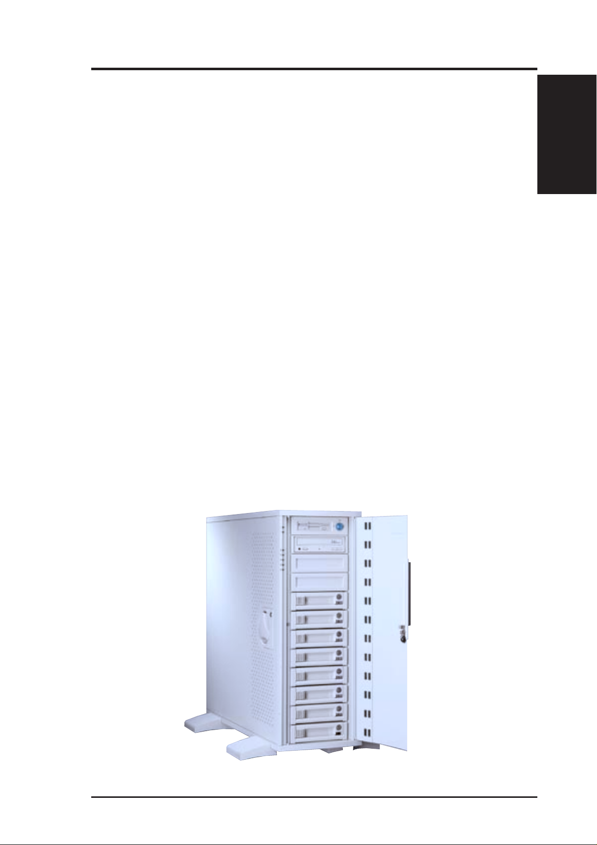
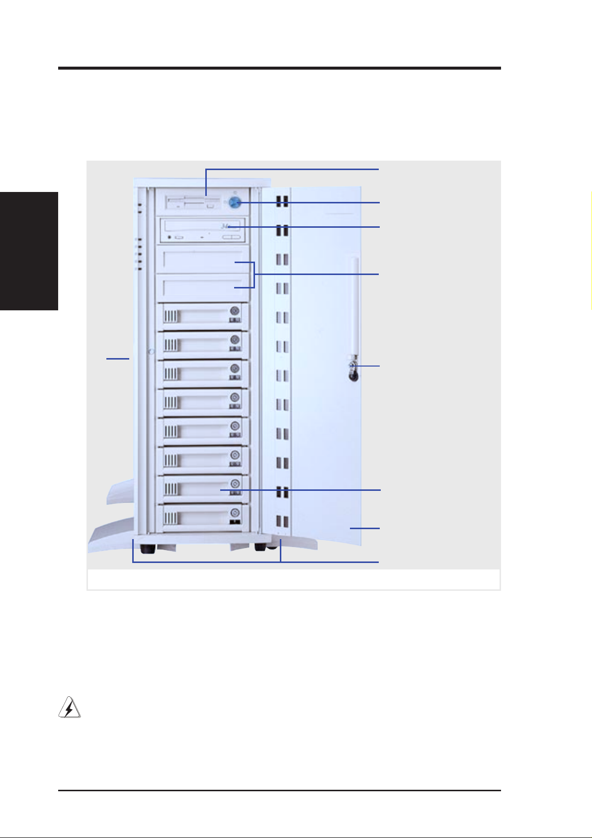
The front side of the server is provided to show the front exterior components of this server. The chassis is made of strong rust-resistant metal and
covered with a protective ivory surfacing.
Floppy Drive
Server Front Side
II. Components
Metal Side Access Panel
ATX Power Button
CD-ROM Drive
Fixed Device Bays
(empty)
Metal Door Lock
Hot Swap Tray
Metal Security Door
Stabilizers with wheels
Server front side
WARNING: Always remove the power cord when working on the server
internal components to prevent electrical shocks or damage to electrical
components. ATX power supplies that are plugged into an AC outlet always
have standby power even when the server is powered OFF.
12 AP7500 Hardware Reference Guide
Page 13
II. System Components
Server Back Side
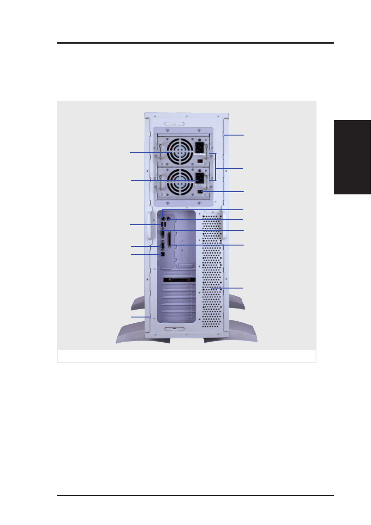
The back side of the server is provided to show the back exterior components of this server.
Intrusion Switch
(inside)
Power Supply Fan
Redundant Power
AC Power In
Connector
USB Ports 1 and 2
Supply
Voltage Input Switch
PS/2 Keyboard
PS/2 Mouse
Serial Port COM1
II. Components
Server Back Side
VGA Connector
LAN Connector
Intrusion Switch
(inside)
Server back side
Parallel Port
Circulation System
Outlet Vents
Chassis Security
To protect the server chassis from unauthorized intrusion, the chassis side
panels and front panel can be locked with the built-in keylock. Chassis intrusion switches can be connected to the motherboard’ s “chassis” connector
to allow monitoring of the chassis side panels’ open/close status. If either
one or both of the side panels are opened, the motherboard’ s onboard hardware monitor can provide alerting and logging with the provided management software.
AP7500 Hardware Reference Guide 13
Page 14
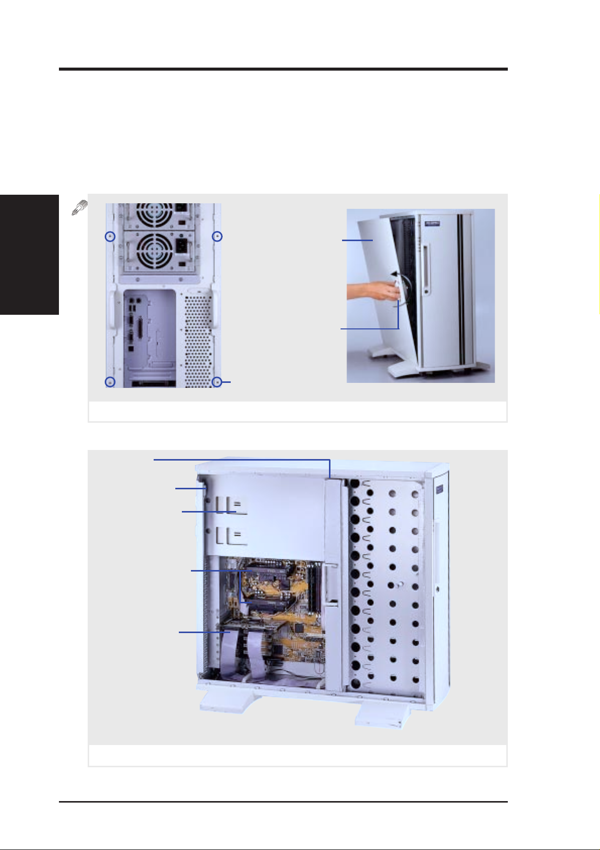
Chassis Panels
There are two identical side panels on the chassis, one on each side. Each
panel is secured by two screws on the back of the server (circled below) and
also by a CAM. The CAM has a rotating knob with its own keylock. T urn the
knob counterclockwise to release and clockwise to secure. The keylock can
be used to keep the knob from being turned by unauthorized people.
II. Components
Chassis Panels
II. System Components
Left Side Panel
Left Panel Knob
Left side panel
Fan Module
Intrusion Switch
Redundant Power
Supply Frame
Pentium II processors
SCSI RAID Card
Side Panel Screw
Server left side
14 AP7500 Hardware Reference Guide
Page 15
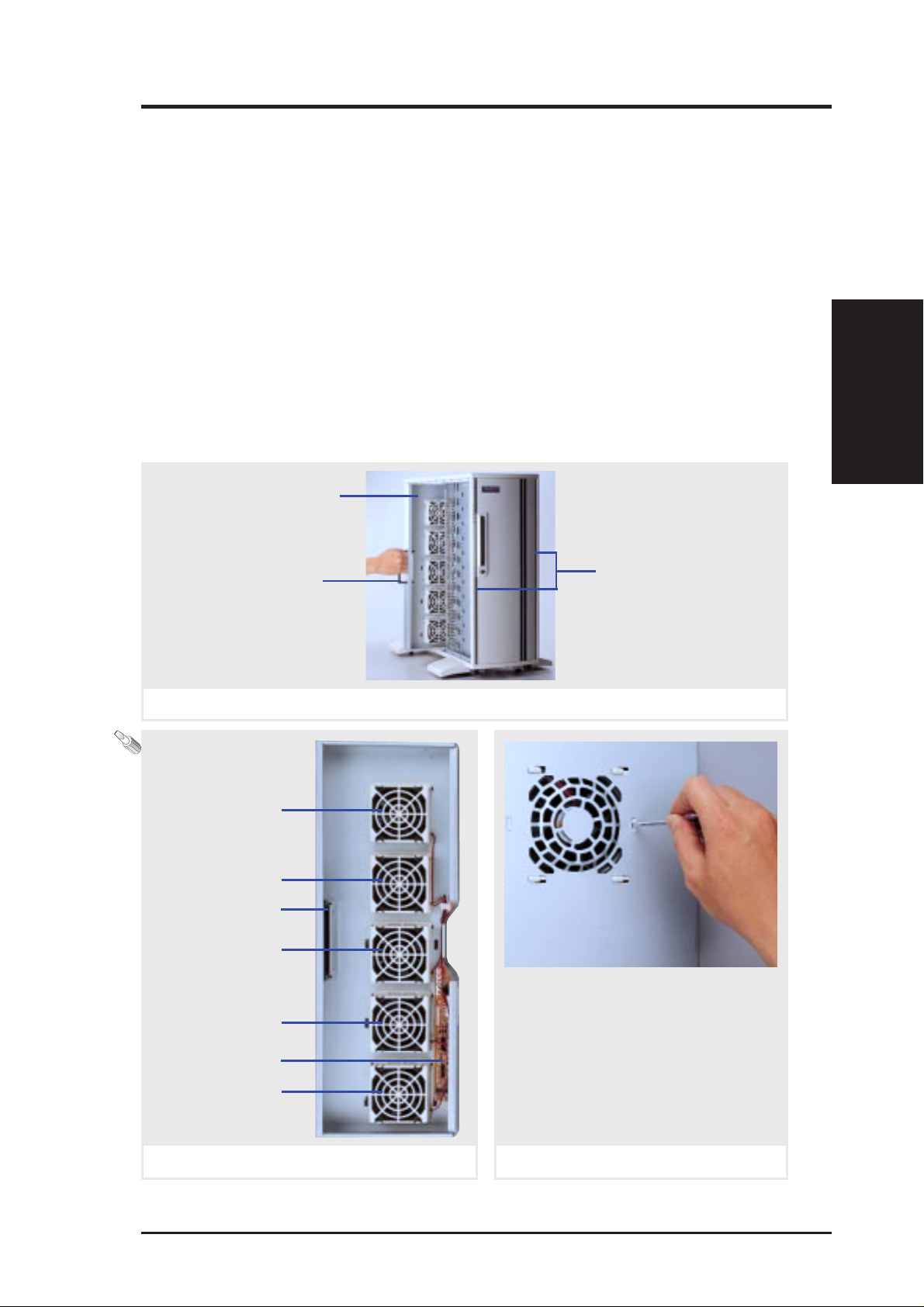
II. System Components
Circulation System
The server’s air circulation system is comprised of five 3 inch (8 cm) fans
mounted on a metal fan module. The circulation system cools the hard disk
drives by bringing fresh air in from the front and forcing the hot air out
through the back. It is important to keep the air surrounding the hard disk
drives below 122˚F (50˚C) to prevent hard disk failures.
Fan Replacement
The fan module can be removed by pulling the handle and inserted by pushing. The handle must be in the out position to insert the fan module. The
individual fans are secured by two clips and two hooks. T o release these clips,
use a screw driver to push these clips in and then slide the fan out. If an
individual fan fails, remove the fan and send it back to the vendor for replacement. If all five fans fail, it may be that the fan control board needs replacing,
remove the control board and send it back to your vendor for replacement.
Fan Module
II. Components
Circulation System
Release Handle
Removing or inserting the fan module
Fan 1
Fan 2
Release Handle
Fan 3
Fan 4
Control Board
Fan 5
Air Inlet Vents (along
full length of door)
When replacing fans, be sure that
the fan rotations are in the same
direction. Use the manufacturer’s
sticker on one side of the fan as a
reference as to the correct side.
Air flows from the front of the
server to the rear .
Fan module
Fan removal (module’s reverse side)
AP7500 Hardware Reference Guide 15
Page 16
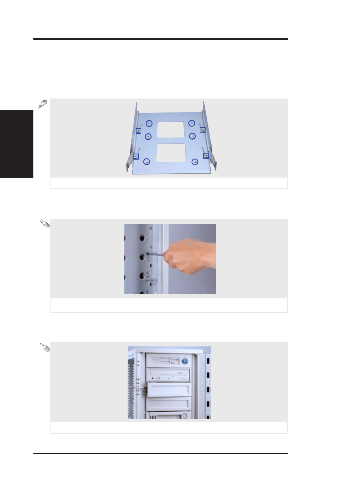
Fixed Storage Device Tray
Internal fixed storage devices are mounted on removable trays. There are
four available, one for a floppy device and another three for full-size devices. There are six screws provided (as circled) for mounting a 4 inch device such as a floppy or hard disk drive. Four screws are provided (as boxed)
for mounting a 6 inch device such as a CD-ROM or tape drive.
Fixed Storage Devices
II. Components
Fixed storage device tray
Fixed Device Bay Cover Clips
The device bay panel is held by two plastic clips on each side. Press these
clips in with a screwdriver to release.
II. System Components
Removing the device bay cover clips
Fixed Device Bay Cover
After releasing the device bay cover clips, pry the cover away from the
chassis using a screw driver from the front.
Removing the device bay cover
Internal Fixed Storage Device Tray
16 AP7500 Hardware Reference Guide
Page 17
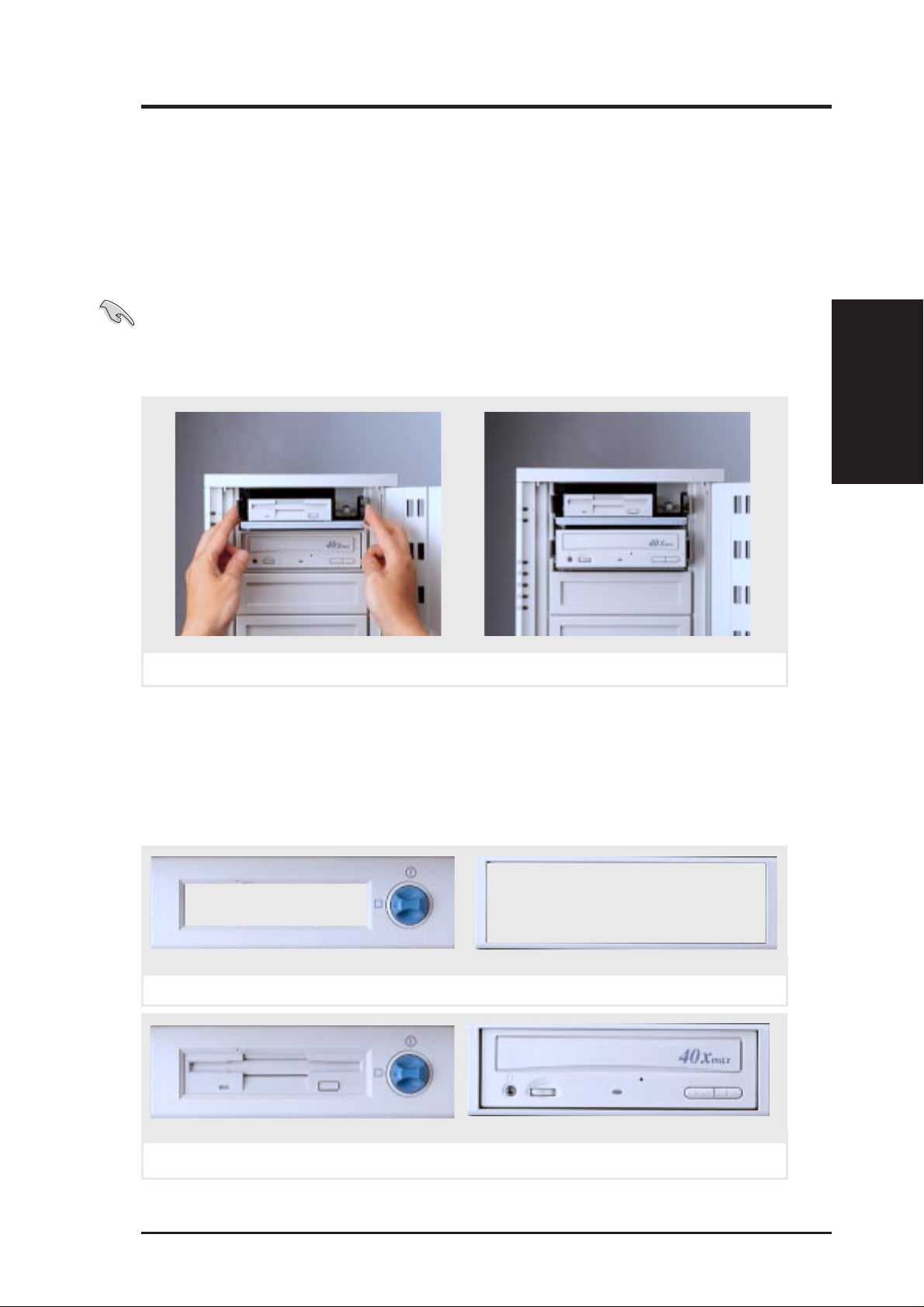
II. System Components
Fixed Storage Devices
Floppy Drive and CD-ROM
The floppy drive fits in the topmost bay along with the power button. A CDROM can fit into either the second, third, or fourth bay from the top. A
metal clip on each side of the device tray secures the tray in place. Press
inward to release the clips. The tray slides in or out on the side rails.
IMPORTANT: If using an IDE hard disk drive in this large chassis, it is recom-
mended that only one is installed and with the shortest IDE cable possible. Long
IDE cables will cause poor signal. Select “...PIO/DMA Mode : 3/1” in BIOS
CHIPSET FEATURES SETUP for a more stable IDE operation.
II. Components
Floppy / CD-ROM
Removing a floppy or CD-ROM drive
Floppy Drive and Storage Device Spacers
Spacers are required for cosmetics only. A floppy drive spacer is used to
cover the floppy drive and power button. A standard storage device spacer
is used to cover the CD-ROM, tape drive, or additional CD-ROMs. You
should purchase an extra spacer for each storage device.
Floppy Drive Spacer
Floppy and CD-ROM drive spacers
Fixed Device Spacer
Floppy drive with spacer
Floppy and CD-ROM drives
AP7500 Hardware Reference Guide 17
CD-ROM with spacer
Page 18
II. Components
Hot-Swap Trays
II. System Components
Hot-Swap T rays
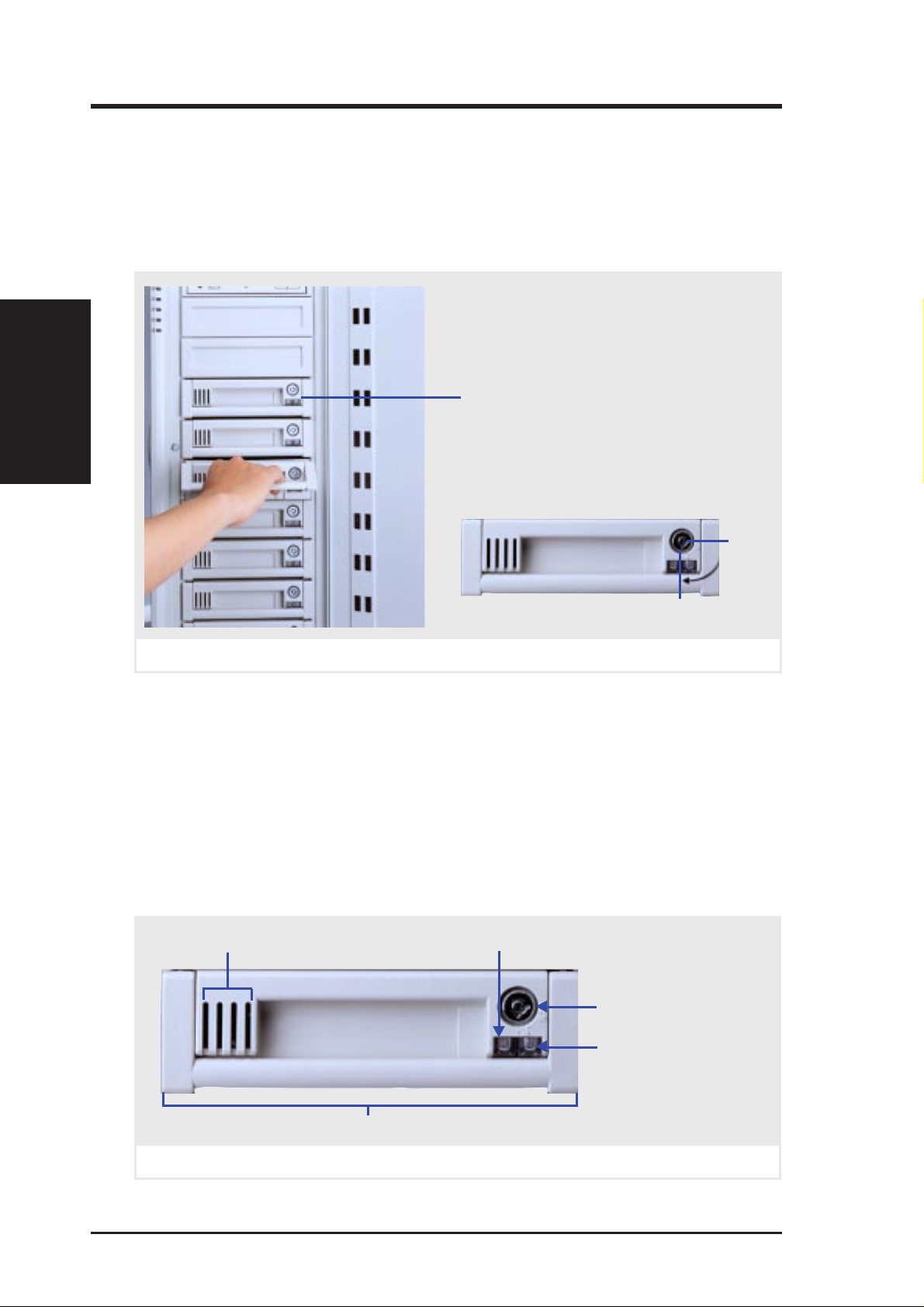
Maximum uptime in a server requires devices that can be easily replaced or
“swapped.” The main hard disks are mounted in internal hot-swap trays for
easy replacement. T o remove the tray , unlock the tray and pull on the handle.
A lock secures the handle and switches on or off the power to the hard drive.
Hot-Swap Tray (8 Total)
Hot-Swap Tray Keylock Positions
Lock/
Power
On
Unlock/
Power Off
Removing or inserting the hot-swap tray
Hot-Swap T ray Interface
The front of the hot-swap tray provides a keylock in order to switch the
power on, which also locks the handle, and switch the power off, which also
releases the handle. T wo LEDs provide information on the power and activity status of the hard disk drive. When power is received by the hot-swap
tray’s connector board, the power LED will light. When data is written or
read to or from the contained hard disk drive, the activity LED will flash
proportional to the amount of data transferred.
Air
Inlet
Activity LED
(SLED)
Keylock / Power Switch
Power LED (PLED)
Release / Transport
Handle
Hot-swap tray face plate
18 AP7500 Hardware Reference Guide
Page 19
II. System Components
Hot-Swap T ray Usage
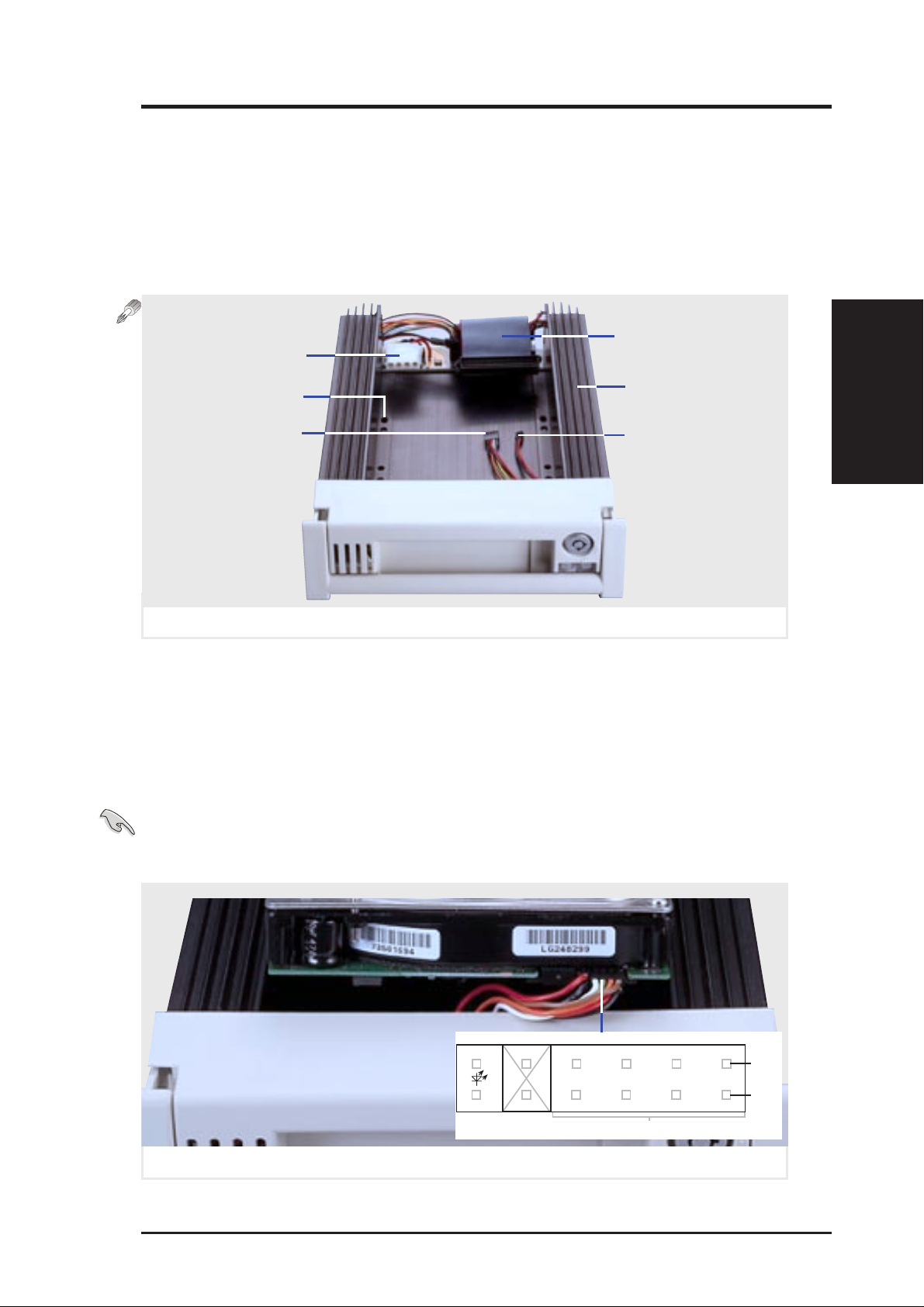
Each hot-swap tray provides an aluminum carrier for a single SCSI hard
disk drive with a maximum height of 1 5/8 inch, width of 4 inches, and
length of 6 inches. The aluminum tray provides protection and maximum
heat dissipation for almost all types of high speed SCSI disk drives. The
provided cables and wires connect to the SCSI hard disk drive and screws
are needed to secure the tray to the bottom of the SCSI hard disk drive.
SCSI Cable
Power Connector
Screw Holes
SCSI ID
Aluminum Tray
Activity LED
(ALED)
Hot-swap tray and its connectors
Hot-Swap Tray Front Connections
The hot-swap tray provides wires for connecting the activity LED, power
LED, SCSI ID, power, and SCSI signal. Connect the 8 pin connector to the
SCSI Address pins according to the colors shown. Connect the 2 pin connector to the activity signal pins according to the colors shown.
IMPORTANT: The following is only an example. Always consult your
hard disk drive documentation or labels for the exact wiring specific to your
hard disk drive make and model.
Hot-Swap Tray
II. Components
Seagate Cheetah (ST34501W) side opposite power & SCSI
Red
Unused
Black
Activity
Signal
White
Blue Black
SCSI Address (ID#)
Orange
Green Brown
Yellow
Red
Hot-swap tray SCSI ID & activity LED wires connected (Seagate HD)
AP7500 Hardware Reference Guide 19
Pin 1
1248
Pin 2
Page 20
II. System Components
Hot-Swap Tray Connector Board
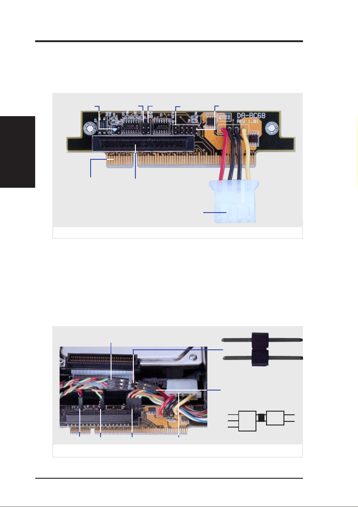
The connector board is mounted on the hot-swap tray to interface with the
SCSI backplane in the chassis. The connector board combines all the signal
and power into one docking connector for a simple hot-swap unit.
Hot-Swap Connector
II. Components
Hot-Swap Tray
Docking Connector
Hot-swap tray connector board parts
Hot-Swap Tray Rear Connections
KEY: These 2 pins connect to the keylock on the tray’s front panel to turn on
and off the drive’s power.
PLED: These 2 pins connect to the power LED on the tray’s front panel to
show when the connector board receives power.
SCSI_ID: These 8 pins connect to the hard disk drive’s SCSI address pins
to set the SCSI ID number of the hard disk drive.
SLED & ALED: These two wires are connected as illustrated below.
from tray’s front panel 3 pin
activity LED (SLED wire)
KEY
SLED
(not used)
Wide SCSI
Connector
ALED_IN
PLED
Hard Disk Drive
Power Connector
(not used)
SCSI_ID
Connector Bridge for LED
from hard disk drive’s 2 pin
activity LED (ALED wire)
KEY PLED SCSI_ID Power
Hot-swap tray rear connections (Seagate HD)
20 AP7500 Hardware Reference Guide
Green
Black
Red
SLED
(wire)
Bridge
Red
Black
ALED
(wire)
Page 21
II. System Components
Motherboard Securing
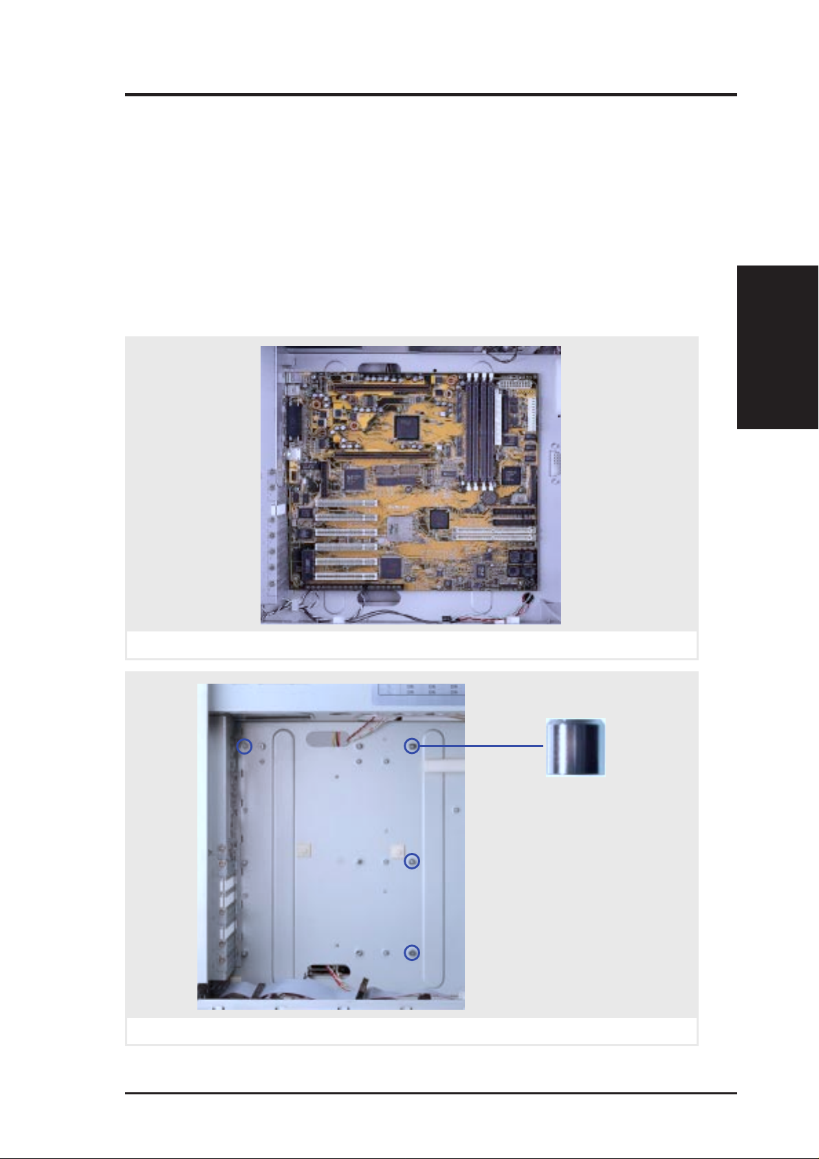
Remove the fan module before installing or removing the motherboard. All
screws are necessary to provide the needed stabilization to support all the
motherboard expansion cards used in a server.
Spacer Mounts
These spacers are used to give added support to the motherboard. Make
sure that these are placed in the screw mount locations shown here for the
P2B-D2 motherboard, do not place them in other locations or else damage
may occur to the motherboard.
II. Components
Motherboard Secure
Installed P2B-D2 motherboard
Motherboard spacer mounts
Spacer Mount
(four required)
AP7500 Hardware Reference Guide 21
Page 22
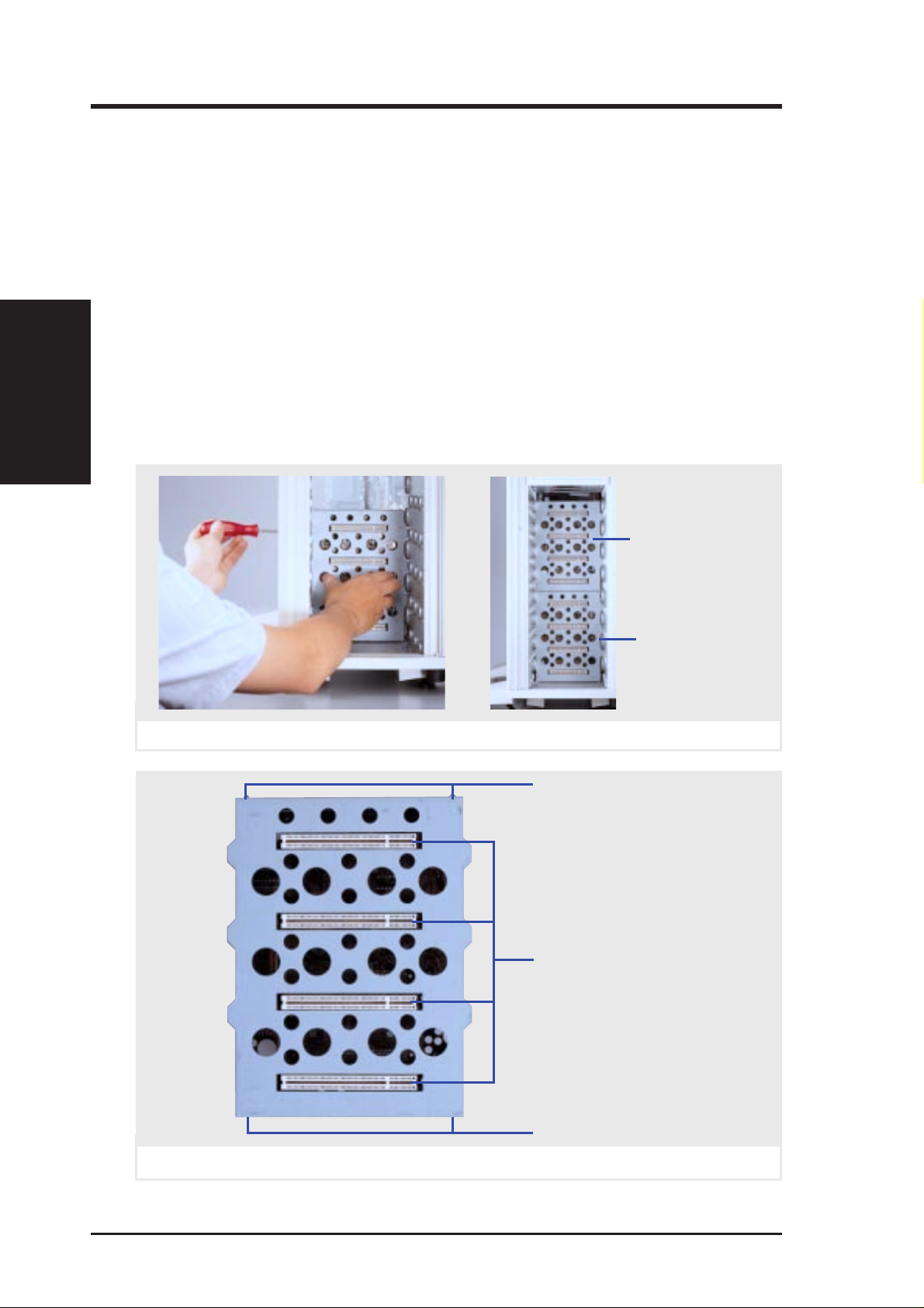
SCSI Backplane
The SCSI backplane of this server is comprised of two SCSI boards with a
Wide-SCSI connector , power input, and SCSI ID dip switches on each SCSI
board. This configuration allows Wide-SCSI hard disk drives to be docked
into the server using a common connector . The female end is located on the
SCSI board, while the male end is located on the hot-swap tray.
SCSI Board Placement
II. Components
SCSI Backplane
There are three screws on each side of the SCSI board. Both sides of the
cabinet side panels must be removed to access these screws. Please note
that notches on the top and bottom of the SCSI board must be placed as
shown in order to properly seat the SCSI boards into the chassis. The SCSI
board will only fit in one orientation but may be interchanged between the
top and bottom half. Be aware of the SCSI ID setting of each SCSI board.
II. System Components
Top Half
SCSI board placement
Bottom Half
Notch Out (top)
Four SCSI Board
Docking Connectors
Notch In (bottom)
SCSI board front side
22 AP7500 Hardware Reference Guide
Page 23
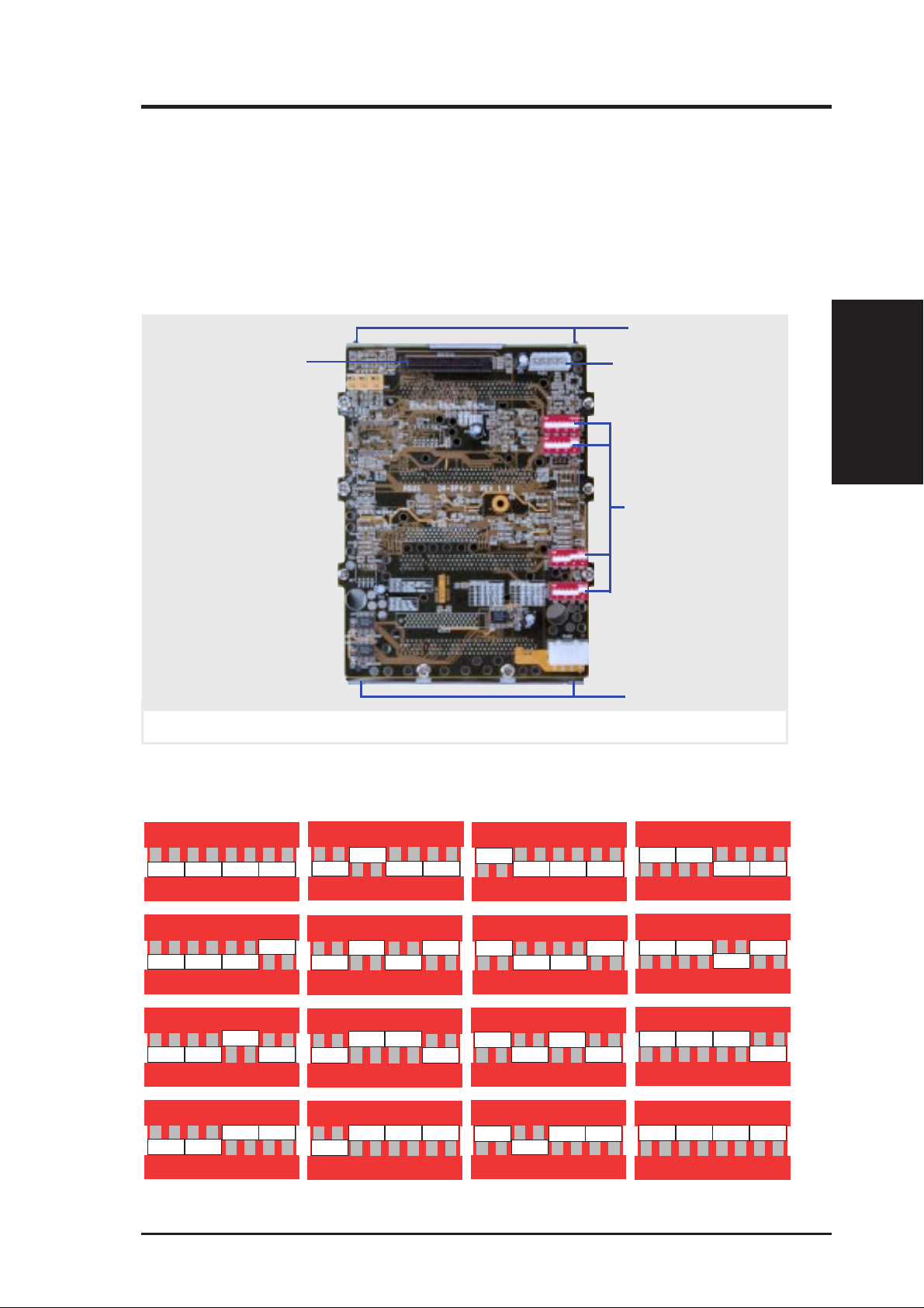
II. System Components
SCSI ID Setting
SCSI ID settings are made through DIP switches located on the SCSI board.
Each SCSI board IDSEL switch has default settings as labeled below. The
default settings were set for use with a 2-channel SCSI card. Each channel
may repeat the SCSI ID numbers of another channel. Make sure that each
IDSEL switch (on each channel) has its own unique setting if making changes
to these switches. See next page for more information on SCSI ID settings.
Notch Out (top)
68pin Wide SCSI
SCSI Board Power
Connector
IDSEL0
IDSEL1
SCSI ID Switches
IDSEL2
IDSEL3
Notch In (bottom)
SCSI board back side
SCSI ID Dip Switches
The following illustrates the different possibilities using the dip switches.
SCSI ID Setting
II. Components
ON
Setting for SCSI ID #0
ON
Setting for SCSI ID #1
ON
Setting for SCSI ID #2
ON
Setting for SCSI ID #3
IDSEL0 Default
IDSEL1 Default
IDSEL2 Default
IDSEL3 Default
ON
Setting for SCSI ID #4
ON
Setting for SCSI ID #5
ON
Setting for SCSI ID #6
ON
Setting for SCSI ID #7
ON
Setting for SCSI ID #8
ON
Setting for SCSI ID #9
ON
Setting for SCSI ID #10
ON
Setting for SCSI ID #11
ON
Setting for SCSI ID #12
ON
Setting for SCSI ID #13
ON
Setting for SCSI ID #14
ON
Setting for SCSI ID #15
AP7500 Hardware Reference Guide 23
Page 24

SCSI Information
SCSI Connections
Your server can support up to 15 user installed single-ended SCSI devices.
Be sure to include both internal and external SCSI devices in your device
setup. Each SCSI device (both internal and external) must have a unique
address (or SCSI ID). Check your SCSI device documentation for instruc-
SCSI Information
II. Components
tions. Be sure to record all SCSI addresses so that you can prevent SCSI
address conflicts.
SCSI Termination
SCSI devices are connected together in a “chain” by cables. Internal devices connect to the motherboard with a 50 pin or 68 pin flat ribbon cable.
External SCSI devices may be connected using an external SCSI connector
or SCSI card with an external connector . If there are more than one internal
or external device, additional devices are connected with cables to form a
“chain.” Terminating the SCSI Bus “chain” is necessary for SCSI devices
to work properly . SCSI devices normally come with its termination enabled
by jumpers or dip switches. You must disable these termination for devices
in between the SCSI chain. Ultra2 devices do not have a termination jumper
and must be terminated using a terminator on the SCSI cable. The terminator must always be on the end of the cable which means that you cannot
connect a device on the last connector.
II. System Components
SCSI ID Jumpers
All SCSI devices, including this motherboard with onboard SCSI, must have a SCSI
identification number that is not in use by any other SCSI device. There are sixteen
possible ID numbers, 0 through 15. The SCSI ID serves two purposes:
• It uniquely defines each SCSI device on the bus.
• It determines which device controls the bus when two or more devices try to use
it at the same time.
SCSI IDs on one channel do not interfere with the IDs on another channel. You can
connect up to 15 SCSI devices to this motherboard. You must set a SCSI ID number
(ID 0 to ID 15) for each device. Note that the onboard SCSI chipset is also a SCSI
device and will also require a SCSI ID number . SCSI devices vary in how they set the
ID number . Some use jumpers, others have some kind of selector switch. Refer to the
manual for any device you install for details on how to set its ID number .
SCSI ID Priority
The motherboard has an onboard 16bit single-channel SCSI chipset. SCSI ID 15
has the highest priority, and SCSI ID 0 has the lowest priority.
24 AP7500 Hardware Reference Guide
Page 25
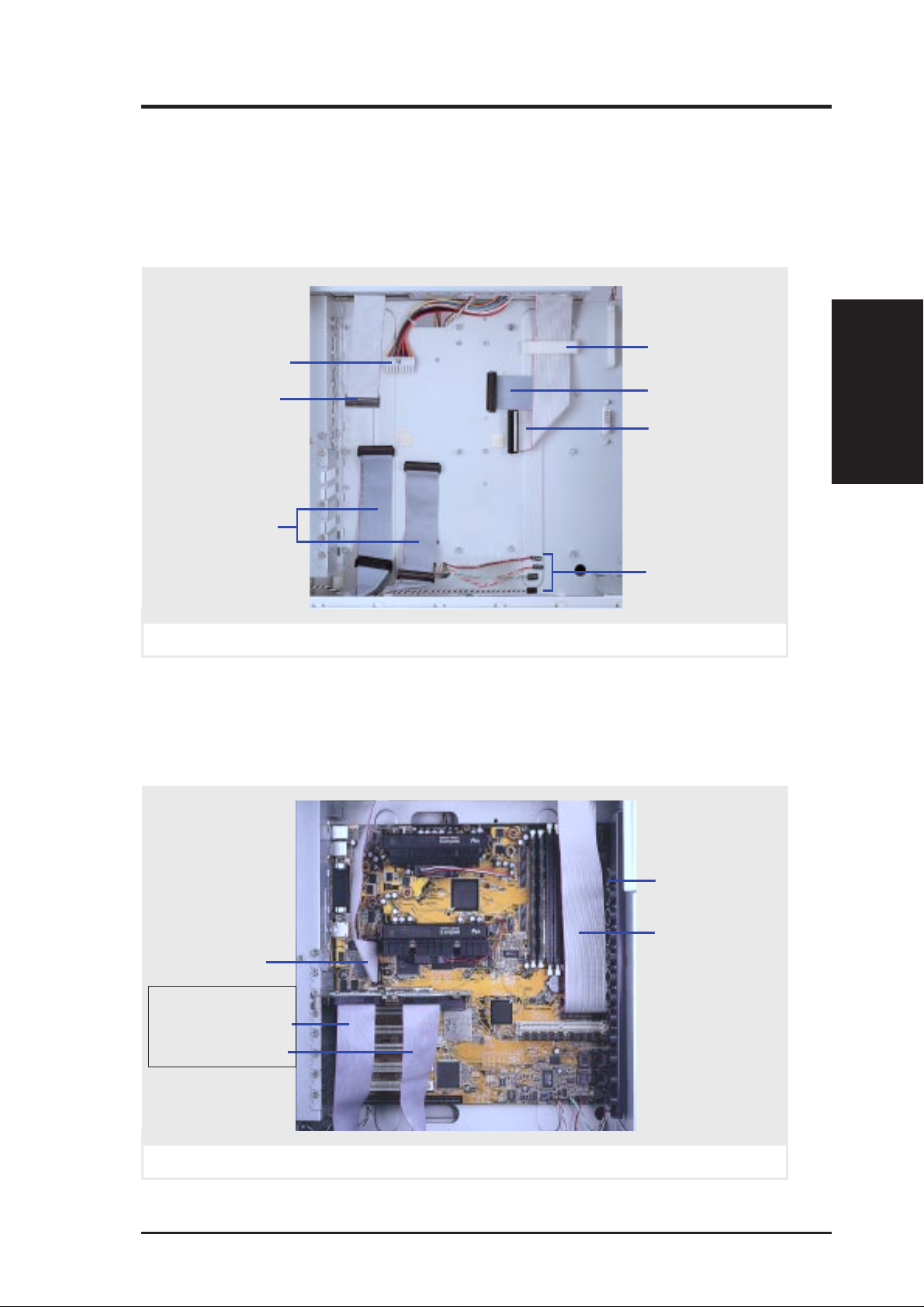
II. System Components
Device Cables
Several cables are used for connecting devices in the server. The following
picture points out the name of each cable and its suggested location. Plastic
keepers protect the cables from contact with the fans and other devices.
Make sure that all cables are properly secured.
ATX Power
Connector
Floppy Cable
68-pin WideSCSI Cables
(for RAID card)
Cables from devices
Plastic Keeper
68-pin Wide-SCSI
for onboard SCSI
IDE Cable
(CD-ROM)
Panel Connectors
Cable Connections
The cables connect to the motherboard as shown. The P2B-DS includes
onboard SCSI with 68-pin and 50-pin SCSI connectors. RAID connections
require the ASUS PCI-DA2100A RAID card.
Device Cables
II. Components
Floppy Cable
ASUS RAID Card:
SCSI Cable Ch. 0
SCSI Cable Ch. 1
Motherboard with cables connected
AP7500 Hardware Reference Guide 25
SCSI Cable
(underneath)
IDE Cable
Page 26
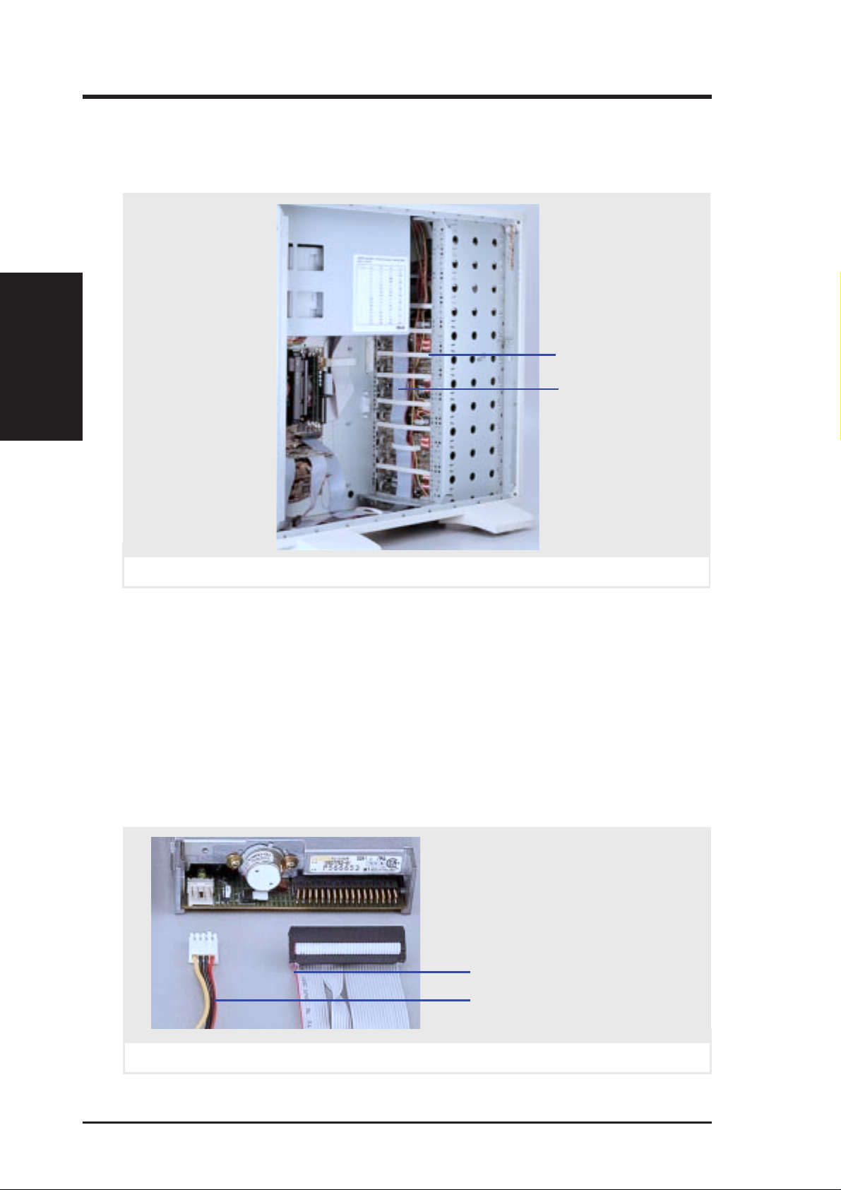
Device Connections
The following picture gives an example of how the server looks with all its
cables connected to both standard and optional components.
Connections / Floppy
II. Components
II. System Components
Plastic Keeper
SCSI Cables
Cables connected to devices
Floppy Disk Drive (1.44MB)
The 1.44MB floppy disk drive requires signal and power connections. The
power connection is easy since it only fits one way and a latch is available
to secure it when fully inserted. The signal cable is tricky because the cable
fits in both orientations as well as shifted one direction or the other. The
signal cable also has no latch to determine when full insertion is made.
Align the red stripes of the signal and power cables so that they face each
other. Carefully insert the connector while visually watching the progress
so that proper alignment and insertion is made.
Red stripe of signal cable
Red stripe of power cable
1.44MB floppy disk drive connections
26 AP7500 Hardware Reference Guide
Page 27
II. System Components
IDE Cabling
Proper IDE device operation requires that the IDE ribbon cable does not
exceed 18 inches. If only one IDE device is used, connect it to the end of the
cable. Remove unused cables from the motherboard’s IDE connector to
ensure proper signal strength.
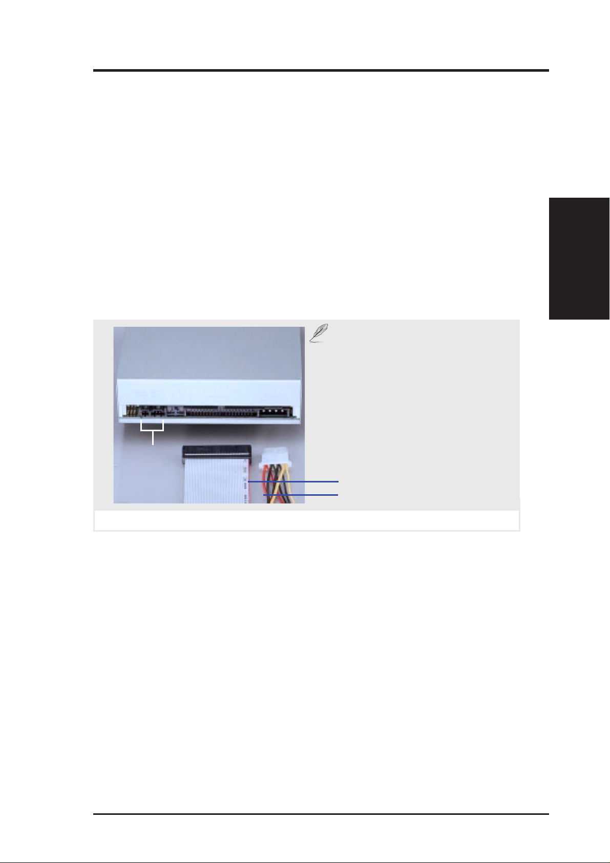
CD-ROM Disk Drive (IDE)
The CD-ROM disk drive mounts only in one of the three fixed device bays
and requires signal and power connections like that of IDE hard disk drives.
The power and signal cable is straightforward with connectors designed to
only fit correctly. The red stripe of the signal and power cables should face
each other.
NOTE: A CD-ROM audio cable is
also provided in case you install an audio card. The only function of the audio
cable is to direct music CD audio signal to your audio card. Computer CDROMs have data (such as *.wav,
*.mpg, *.avi) that travels through the
CD audio
output
signal cable.
II. Components
IDE Cable / CD-ROM
CD-ROM drive connections
Red stripe of signal cable
Red stripe of power cable
AP7500 Hardware Reference Guide 27
Page 28
Ultra2 SCSI Disk Drive
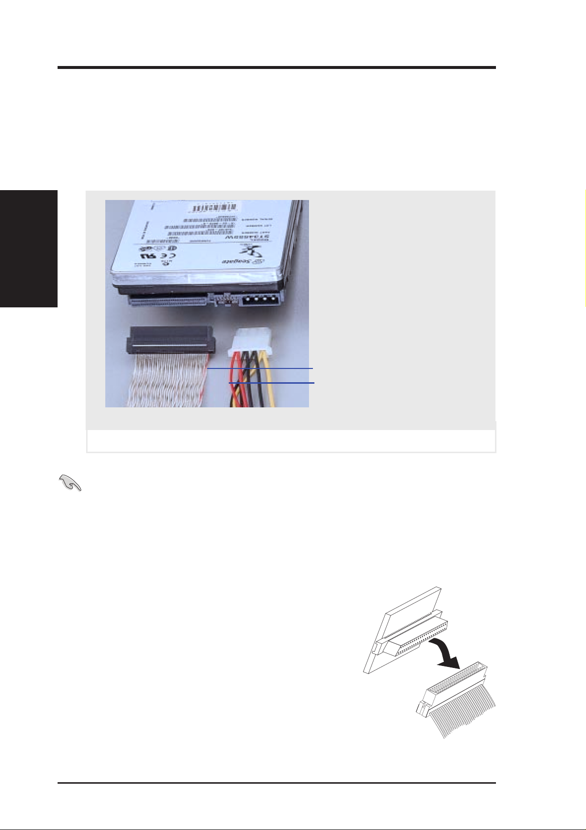
The Ultra2 SCSI disk drive has separate signal and power connections. The
power connector is the same as standard hard disk drive power. The signal
cable is different. For proper signal stability in Ultra2 speeds, a special twisted
ribbon cable must be used. Each pair of wires are twisted for signal shielding like that of high speed (e.g. category 5) LAN cabling.
Ultra2 SCSI Drive
II. Components
II. System Components
Red stripe of signal cable
Red stripe of power cable
Ultra2 SCSI hard disk drive connections
IMPORTANT: Y ou must use Ultra2 SCSI ribbon cables for Ultra2 devices.
Ultra2 ribbon cables (may be colored red and white) are similar to wideSCSI ribbon cables (normally colored gray) but each pair of wire is twisted
to reduce signal interference.
External Ultra2 SCSI Terminator
To prevent SCSI signal loss, the provided external SCSI terminator must be used at the end of the
68-pin SCSI cable. 50-pin SCSI cables may also
use terminators but usually use termination jumpers on the device itself. Currently W ide-SCSI devices have termination jumpers but Ultra2 devices
do not. Some manufacturers ship SCSI devices
with the terminator set, others do not. All termination jumpers must be removed along the cable
where the external SCSI terminator is used.
28 AP7500 Hardware Reference Guide
Page 29
II. System Components
Expansion Cards
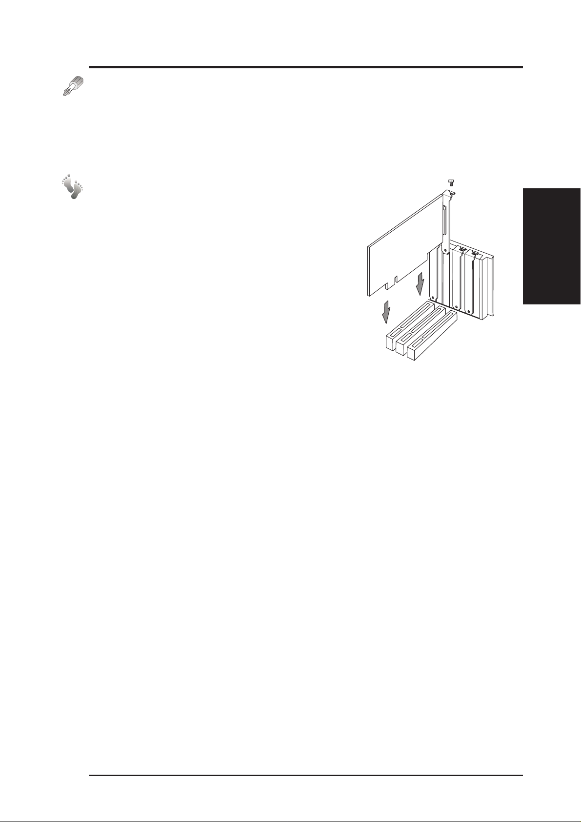
Expansion cards can be easily installed just like any standard PC computer .
Up to 4 PCI or 2 ISA (1 slot is shared allowing a maximum of 5 cards at one
time) cards can be installed. One AGP slot is also available for a hardware
3D accelerator with an AGP connector.
Expansion Card Installation Procedure:
1. Follow the static precautions described in the
front of this manual.
2. Switch OFF your system and all peripheral devices and remove the main power cord.
3. Remove the side panel to the chassis.
4. Find an unused expansion slot on the motherboard and unscrew the metal cover plate from
the slot and put the screw to one side.
5. Ensure the jumpers (if any) are correctly set on
your expansion card
6. Align the card’ s connector with the expansion slot
on the motherboard and gently lower and push the card into the free slot.
7. Secure the card to the expansion slot with the screw you removed from
the metal plate.
8. Attach cables or wires if necessary.
9. Reinstall the side panel if no other work is needed inside the chassis.
II. Components
Expansion Cards
AP7500 Hardware Reference Guide 29
Page 30

Power Supply
This server has a special redundant power supply with specifications to surpass this server’s requirements. A clearly marked label gives detailed specifications of the power supply . A power switch is not provided therefore it is
necessary to remove the power cord before opening the side panel in order
to shut off the standby power . W ith the power cord removed, you can ensure
there are no voltages which can cause shorts while installing or removing
II. Components
Power Supply
internal components.
CAUTION: Before turning ON your server for the first time, set the power
supply’s voltage. Some products may have auto voltage switching to accommodate 220V-240V or 110-120V but this power supply must be set
manually . The factory default should be on 230V to accommodate the higher
voltage but it is safer to visually inspect the switch yourself in case it is not.
Using the power modules set on 115V in 230V environments may cause
damage to the power modules.
II. System Components
IMPORTANT: For countries using 110V-120V, you must slide the switch
to 115V or else power up is not possible (but no damage will occur).
Power Supply Mounting
The redundant power supply is swappable within its own frame. T wo screws
secure the power supply in the inserted position. The entire frame can also
be unscrewed for servicing if necessary. A support brace must be used to
support the frame under the inner edge. The support brace can only be secured after the power supply frame is inserted and must be removed before
the power supply frame is removed from the chassis. There are four screws
securing the power supply support brace as circled below.
Top power module
Power supply frame
Power supply with frame halfway inserted
30 AP7500 Hardware Reference Guide
Bottom power
module
Screwdriver
Securing power supply support brace
Power supply
support brace
Page 31
II. System Components
Power Module Rating
The redundant power supply consist of one frame and two identical ATX
power modules. The power supply must be turned on or off through an ATX
power switch connected to the motherboard’s panel connector. The power
modules are rated at 400W each and have passive current sharing on all
outputs. Each power module supplies up to 400W to share the load but do
not provide 800W combined. If one power module fails, 400W load is supported using one power module.
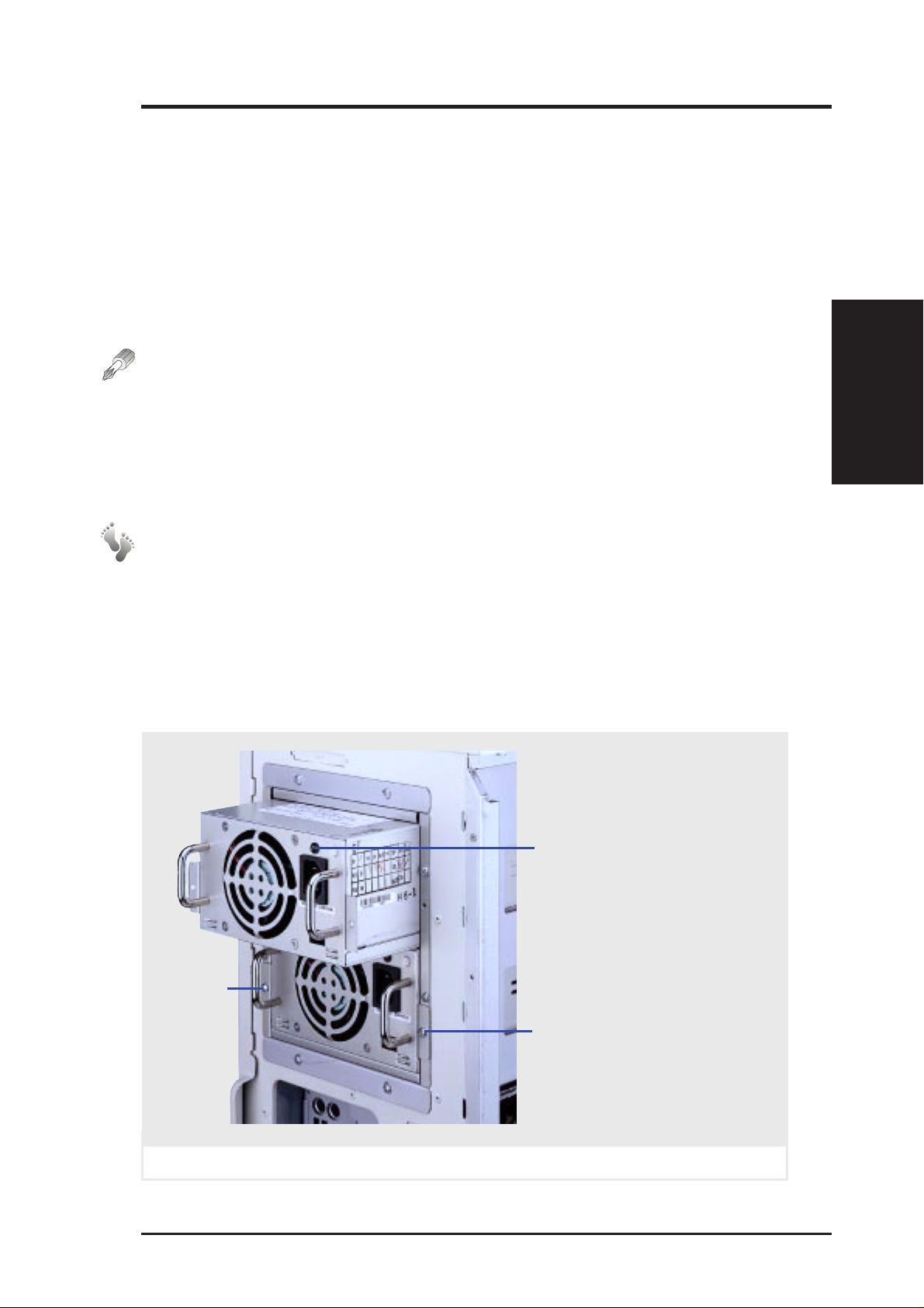
Power Module Failure
If any of the power modules fail to provide a voltage on any of its outputs,
an audible alarm (located in the frame) will sound and the failed power
module’s LED will turn OFF. The power module’s status LED lights when
both input and output voltages are stable and darkens if either the input or
output voltages fail. If the alarm sounds, perform the following steps:
1. Remove the power cord to the failed power module (with dark LED).
Power Modules
II. Components
2. Remove the two screws and slide the failed power module out. The alarm
should stop. If not, there may be a problem with the other module or
with the redundant power supply frame (very unlikely).
3. Reinsert the failed power module and plug in the AC cord to confirm.
4. If the alarm sounds again, remove the failed power module and replace
it with a good one as soon as possible.
Status LED (lights when input/
output voltages are stable and
darkens when either input or
output voltages fail)
Screw
Top power module partially inserted
AP7500 Hardware Reference Guide 31
Power module screw
(one on each side)
Page 32
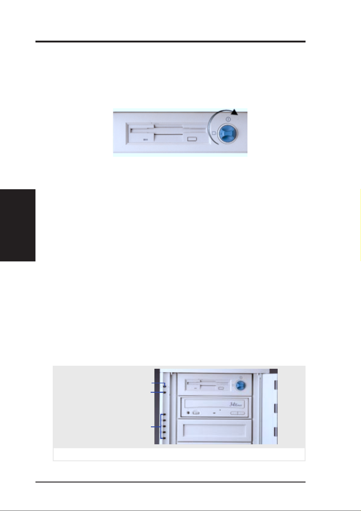
Starting the Server
Turn ON the server by turning the power knob clockwise and pushing inwards
momentarily . The power button will snap back when released because ATX power
systems have an electrical ON /OF F switch unlike AT systems which require a
permanent ON or OFF position. If the Power On LED does not light, make sure
the power cord is connected to the system unit and to a working grounded outlet.
When booting your server for the first time, hold the “Delete” key and enter
BIOS setup in order to make settings. ISA cards requires that you set “IRQ
XX Used by ISA : Yes” in BIOS PNP AND PCI SETUP in order for that
IRQ to be reserved for your ISA expansion card. You need to set “Boot
III. Power Info.
Starting / LED
Sequence : A, C” in BIOS FEATURES SETUP in order to boot from a
floppy diskette to setup your hard disk. Insert a bootable floppy diskette and
select “Save & Exit Setup” from the BIOS main menu. Once your server
has properly booted, an “A:\>” prompt will appear. Use the boot diskettes
provided with the server operating system or create your own. If you are
planning to use RAID on your server, you need to install a RAID card, such
as the ASUS PCI-DA2100A and then run the RAID setup program from a
floppy diskette. Reboot your server with the operating system boot disk in
order to install drivers for your devices (such as CD-ROM and SCSI devices) and install your server operating system. You may be prompted for
manufacturer supplied driver diskettes for each device on your server if
they are not included in the operating system setup drivers.
III. Power Information
LED Indicators
The LED indicators are located on the top-left edge of the front panel. The Power
LED lights when the motherboard receives power from the power supply . Activity LED lights when there is activity from IDE or SCSI devices connected to the
motherboard. Fan #1-5 lights if the corresponding fan stops turning.
Power LED
Activity LED
Fan #1 Error (when lit)
Fan #2 Error (when lit)
Fan #3 Error (when lit)
Fan #4 Error (when lit)
Fan #5 Error (when lit)
LED indicators on front panel
32 AP7500 Hardware Reference Guide
Page 33
III. Appendix
SCSI Cable Limits
SCSI cables have a limit to the length that it may have. Exceeding the length
may cause problems mounting or using any one of the SCSI devices.
CAUTION: Exceeding the SCSI cable limits may cause unreliable data
transfers even if all the devices are mounted properly.
NOTES:
• Narrow refers to 50 pin and W ide refers to 68 pin. Don’t get confused by
the width of the connector or cable.
• The SCSI ID for devices on one connector cannot be the same as the
SCSI ID for devices on the other connectors. None of the devices on any
connector can use ID7, which is reserved for the SCSI controller.
• A maximum of 15 devices may be connected to the motherboard (three
connectors) at one time. The following “Max Devices” are for individual
connectors and do not take into account other SCSI devices.
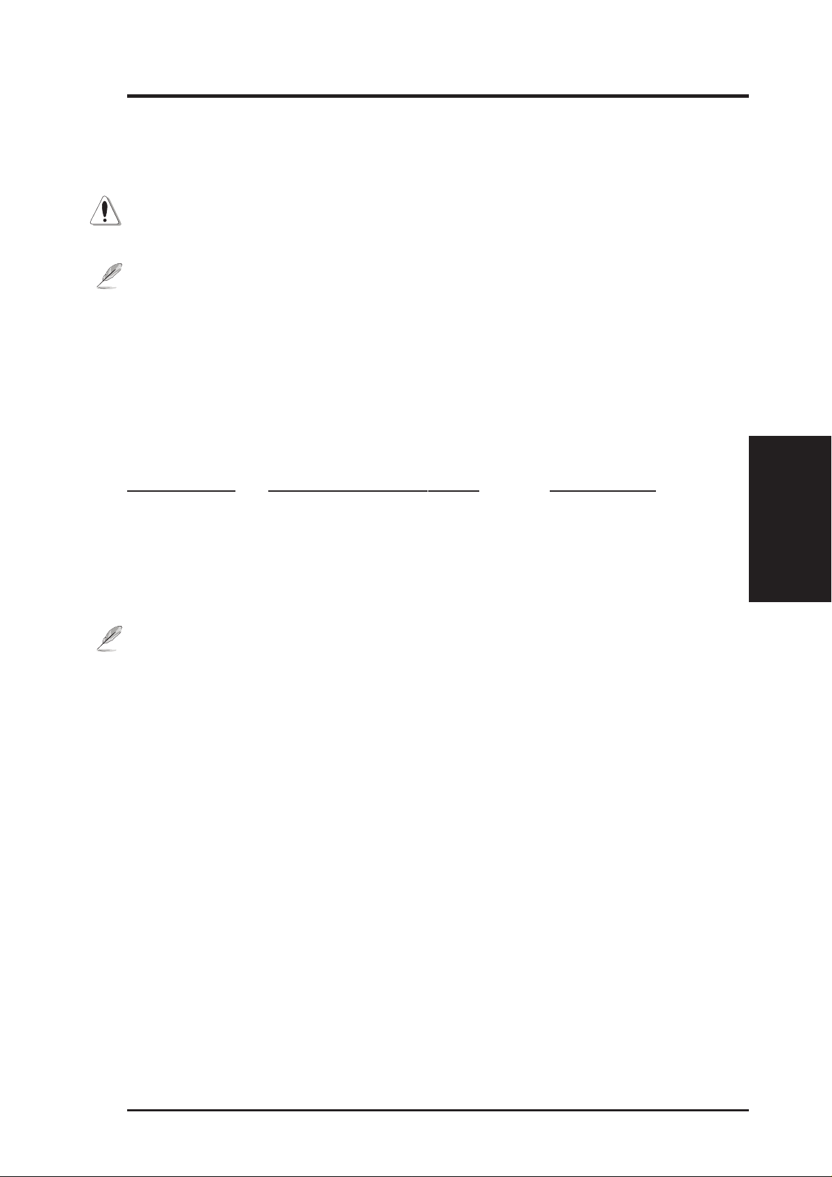
Cable Limits Max Data Transfer Rates Max Devices
1) 12m (29.4ft) Ultra2-SCSI (68 pin 80MB/Sec) 15
2) 3m - 1.5m Wide Ultra-SCSI (68 pin 40MB/Sec) 4 - 8
3) 3m (9.8ft) Wide-SCSI (68 pin 20MB/Sec) 15
4) 3m - 1.5m Narrow Ultra-SCSI (50 pin 20MB/Sec) 4 - 7
5) 3m (9.8ft) Narrow Fast-SCSI (50 pin 10MB/Sec) 7
Notes for the above chart:
1) A total of 15 “Ultra2-SCSI” devices (ID0-ID15) may be connected to the
68-pin Ultra2 connector on the motherboard.
NOTE: If connecting Fast/Ultra devices with Ultra2 devices on the Ultra2 connector, the entire SCSI bus will be limited to the Ultra SCSI
conditions listed above. Mixing SCSI devices is highly not recommended.
2) A total of 8 “W ide Ultra-SCSI” devices (ID0-ID15) may be connected to
the 68-pin Wide connector if using a 1.5m (4.9ft) cable, but only 4 “Wide
Ultra-SCSI” devices if using a 3m (9.89ft) cable. Ultra-SCSI technology
is unstable over long lenghts, therefore stability will depend on they quality of your cable and devices.
3) A total of 15 “W ide-SCSI” devices (ID0-ID15) may be connected to the
68-pin Wide connector .
4) A total of 7 “Narrow Ultra-SCSI” devices (ID0-ID6) may be connected
to the 50-pin Narrow connector when using 1.5m (4.9ft) cable but only
4 devices when using 3m (9.8ft) cable. Ultra-SCSI technology is unstable over long lengths, therefore stability will depend on the quality of
your cable and devices.
5) A total of 7 “Narrow Fast SCSI” devices (ID0-ID7) may be connected to
the 50-pin Narrow connector.
III. Appendix
SCSI Cable Limits
AP7500 Hardware Reference Guide 33
Page 34
Power Supply Information
Input Voltage
Input Current
Output Current Capacity
Power Information
III. Appendix
III. Appendix
Range Min (V) Nom (V) Max (V)
Range 1 90 120 132
Range 2 180 230 264
Input Voltage Max In Cur. Max Inrush Cur.
Range 1 10A 100Ap-p
Range 2 5A 200Ap-p
Output Nom Out (Vdc) Min (A) Max (A)
1 3.3V 0 30*
2 5.0V 3.0 40*
3 12.0V 0.5 15
4 -5.0V 0 0.5
5 -12.0V 0 0.5
* Total output power for 3.3V and 5V combined shall be 210W
Output Voltage Regulation, Ripple, and Noise
Output Voltage Limits (Vdc) Ripple/Noise
Output Min Nom Max Maximum
1 3.17V 3.30V 3.46V 50mVp-p
2 4.80V 5.00V 5.25V 50mVp-p
3 11.40V 12.00V 12.60V 120mVp-p
4 -4.75V -5.00V -5.25V 120mVp-p
5 -11.40V -12.00V -12.60V 120mVp-p
Regulatory Information
Safety
The power system meets all applicable clauses for UL 1950 2nd edition
without D3 deviations. The power system passes all tests for CUL and TUV
safety .
EMI
The power system, operating with resistive load, meets FCC class B and
CISPR 22 class B conducted limits.
34 AP7500 Hardware Reference Guide
Page 35
III. Appendix
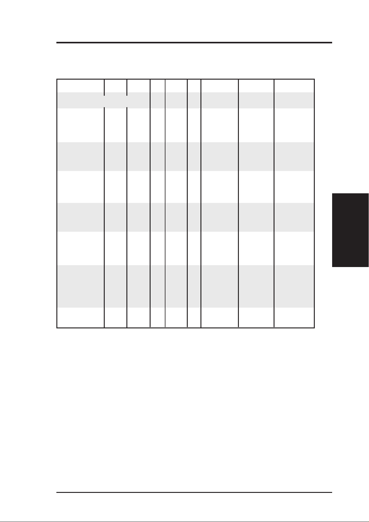
Power Supply Requirement Calculation Table
Item Volts Amp x Qty. = Total Amp Watts (5V) Watts (12V)
Total Motherboard Power
Hard Drive 5.0V 1.3 x =
12V 1.5 x =
CD-ROM 5.0V x =
12V x =
Tape Drive 5.0V x =
12V x =
Floppy Drive 5.0V x =
12V x =
System Fans 5.0V x =
12V 0.3 x = 0.6 7.2
Other 3.3V x =
209.55 3.6
III. Appendix
Power Requirement
Total Power
5.0V x =
12V x =
AP7500 Hardware Reference Guide 35
Page 36

III. Appendix
Glossary
Byte (Binary Term)
One byte is a group of eight contiguous bits. A byte is used to represent a
single alphanumeric character, punctuation mark, or other symbol.
CHKDSK (Check Disk)
An MS-DOS command that gives you information such as disk space, files,
and directories on your hard disk drive.
COM Port
COM is a logical device name used to designate the computer serial ports.
Pointing devices, modems, and infrared modules can be connected to COM
ports. Each COM port is configured to use a different IRQ and address
assignment.
III. Appendix
Glossary
CPU (Central Processing Unit)
The CPU, sometimes called “Processor,” actually functions as the “brain”
of the computer. It interprets and executes program commands and processes all the data stored in memory. Currently, there are socket 7, slot 1,
and slot 2 CPUs. Intel Pentium Processors fit on socket 7, Intel Pentium II
fit on slot 1, and Intel Xeon fit on slot 2.
FDISK (Fixed Disk Setup Program)
An MS-DOS program used to partition the hard disk drive. FDISK is required to setup a new non-RAID hard disk drive before formatting and installing an operating system.
IDE (Integrated Drive Electronics)
IDE devices integrate the drive control circuitry directly on the drive itself,
eliminating the need for a separate adapter card (in the case for SCSI devices). UltraDMA/33 IDE devices can achieve up to 33MB/Sec transfer.
LPT Port (Line Printer Port)
Logical device name reserved by DOS for computer parallel ports. Each
LPT port is configured to use a different IRQ and address assignment.
PCI Bus (Peripheral Component Interconnect Local Bus)
PCI bus is a specification that defines a 32-bit data bus interface. PCI is a
standard widely used by expansion card manufacturers.
36 AP7500 Hardware Reference Guide
Page 37

III. Appendix
Peripherals
Peripherals are components on the outside of the computer such as a monitor, printer, keyboard, or mouse. Peripherals are attached to the computer
via I/O ports. Peripheral devices allow your computer to perform an almost
limitless variety of specialized tasks.
POST (Power On Self Test)
When you turn on the computer, it will first run through the POST, a series
of software-controlled diagnostic tests. The POST checks system memory,
the motherboard circuitry , the display , the keyboard, the diskette drive, CPU,
and other I/O devices.
PS/2 Port
PS/2 ports are based on IBM’s Micro Channel Architecture. This type of
architecture transfers data through a 16-bit or 32-bit bus. A PS/2 mouse and/
or keyboard may be used on ATX motherboards.
RAID (Redundant Array of Inexpensive Disks)
RAID can be set up to provide mirroring (for fault tolerance), parity (for
data guarding), or striping (for data distribution over several drives for increased performance). A RAID card is required to setup a RAID system.
RAM (Random Access Memory)
There are several different types of RAM such as DRAM (Dynamic RAM),
EDO DRAM (Extended Data Out DRAM), SDRAM (Synchronous DRAM).
Glossary
III. Appendix
ROM (Read Only Memory)
ROM is nonvolatile memory used to store permanent programs (called firmware) used in certain computer components. Flash ROM (or EEPROM) can
be reprogrammed with new programs (or BIOS).
SCSI (Small Computer System Interface)
High speed parallel interface defined by the X3T9.2 committee of the American National Standards Institute (ANSI) for connecting many peripheral
devices.
UPS (Uninterruptible Power Supply)
A battery system that can provide power to an electronic device or computer when power fails in the building. A passive UPS only provides power .
An active UPS provides power conditioning that offers protection against
transient power conditions and short-term power outages.
AP7500 Hardware Reference Guide 37
Page 38

(This page was intentionally left blank)
III. Appendix
III. Appendix
38 AP7500 Hardware Reference Guide
Page 39

(This page was intentionally left blank)
III. Appendix
AP7500 Hardware Reference Guide 39
Page 40

(This page was intentionally left blank)
III. Appendix
40 AP7500 Hardware Reference Guide
 Loading...