


G41M-VS3 R2.0
11
11
1
ASRock G41M-VGS3 / G41M-VS3 Motherboard
EnglishEnglish
EnglishEnglish
English
Copyright Notice:Copyright Notice:
Copyright Notice:Copyright Notice:
Copyright Notice:
No part of this installation guide may be reproduced, transcribed, transmitted, or trans-
lated in any language, in any form or by any means, except duplication of documen-
tation by the purchaser for backup purpose, without written consent of ASRock Inc.
Products and corporate names appearing in this guide may or may not be registered
trademarks or copyrights of their respective companies, and are used only for identifica-
tion or explanation and to the owners’ benefit, without intent to infringe.
Disclaimer:Disclaimer:
Disclaimer:Disclaimer:
Disclaimer:
Specifications and information contained in this guide are furnished for informational
use only and subject to change without notice, and should not be constructed as a
commitment by ASRock. ASRock assumes no responsibility for any errors or omissions
that may appear in this guide.
With respect to the contents of this guide, ASRock does not provide warranty of any kind,
either expressed or implied, including but not limited to the implied warranties or
conditions of merchantability or fitness for a particular purpose. In no event shall
ASRock, its directors, officers, employees, or agents be liable for any indirect, special,
incidental, or consequential damages (including damages for loss of profits, loss of
business, loss of data, interruption of business and the like), even if ASRock has been
advised of the possibility of such damages arising from any defect or error in the guide
or product.
This device complies with Part 15 of the FCC Rules. Operation is subject to the
following two conditions:
(1) this device may not cause harmful interference, and
(2) this device must accept any interference received, including interference that
may cause undesired operation.
Published December 2010
Copyright©2010 ASRock INC. All rights reserved.
CALIFORNIA, USA ONLY
The Lithium battery adopted on this motherboard contains Perchlorate, a toxic
substance controlled in Perchlorate Best Management Practices (BMP) regulations
passed by the California Legislature. When you discard the Lithium battery in
California, USA, please follow the related regulations in advance.
“Perchlorate Material-special handling may apply, see
www.dtsc.ca.gov/hazardouswaste/perchlorate”
ASRock Website: http://www.asrock.com
22
22
2
ASRock G41M-VGS3 / G41M-VS3 Motherboard
EnglishEnglish
EnglishEnglish
English
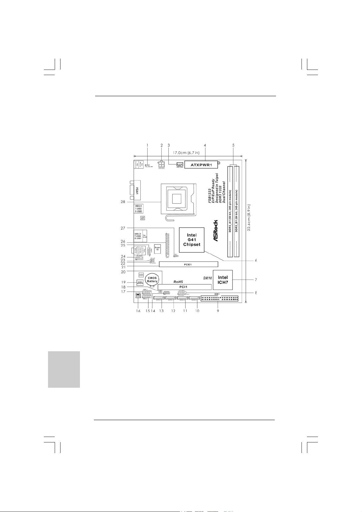
Motherboard LayoutMotherboard Layout
Motherboard LayoutMotherboard Layout
Motherboard Layout
(G41M-(G41M-
(G41M-(G41M-
(G41M-
VGS3 / G41M-VGS3 / G41M-
VGS3 / G41M-VGS3 / G41M-
VGS3 / G41M-
VS3)VS3)
VS3)VS3)
VS3)
1 PS2_USB_PWR1 Jumper 15 USB 2.0 Header (USB4_5, Blue)
2 ATX 12V Conne ctor (A TX12V2) 16 Chassis Fan Connector (CHA_FAN1)
3 CPU Fan Connector (CPU_FAN1) 17 USB 2.0 Header (USB6_7, Blue)
4 A TX Power Connector (ATXPWR1) 18 Clear CMOS Jumper (CLRCMOS1)
5 2 x 240-pin DDR3 DIMM Slots 19 BIOS SPI Chip
(Dual Channel: DDR3_A1, DDR3_B1; Blue) 20 PCI Slot (PCI1)
6 North Bridge Controller 21 PCI Express x16 Slot (PCIE1)
7 South Bridge Controller 22 EUP Audio Jumper (EUP_AUDIO1)
8 System Panel Header (PANEL1, White) 23 EUP LAN Jumper (EUP_LAN1)
9 IDE1 Connector (IDE1, Blue) 24 Front Panel Audio Header
10 Primary SATAII Connector (SA T AII_1; Blue) (HD_AUDIO1, White)
11 Secondary SATAII Connector (SA T AII_2; Blue) 25 Serial Port Connector (COM1)
12 Third SATAII Connector (SATAII_3; Blue) 26 Print Port Header (LPT1, White)
13 Fourth SATAII Connector (SATAII_4; Blue) 27 FSB1 Jumper
14 Chassis Speaker Header (SPEAKER 1, White) 28 775-Pin CPU Socket
33
33
3
ASRock G41M-VGS3 / G41M-VS3 Motherboard
EnglishEnglish
EnglishEnglish
English
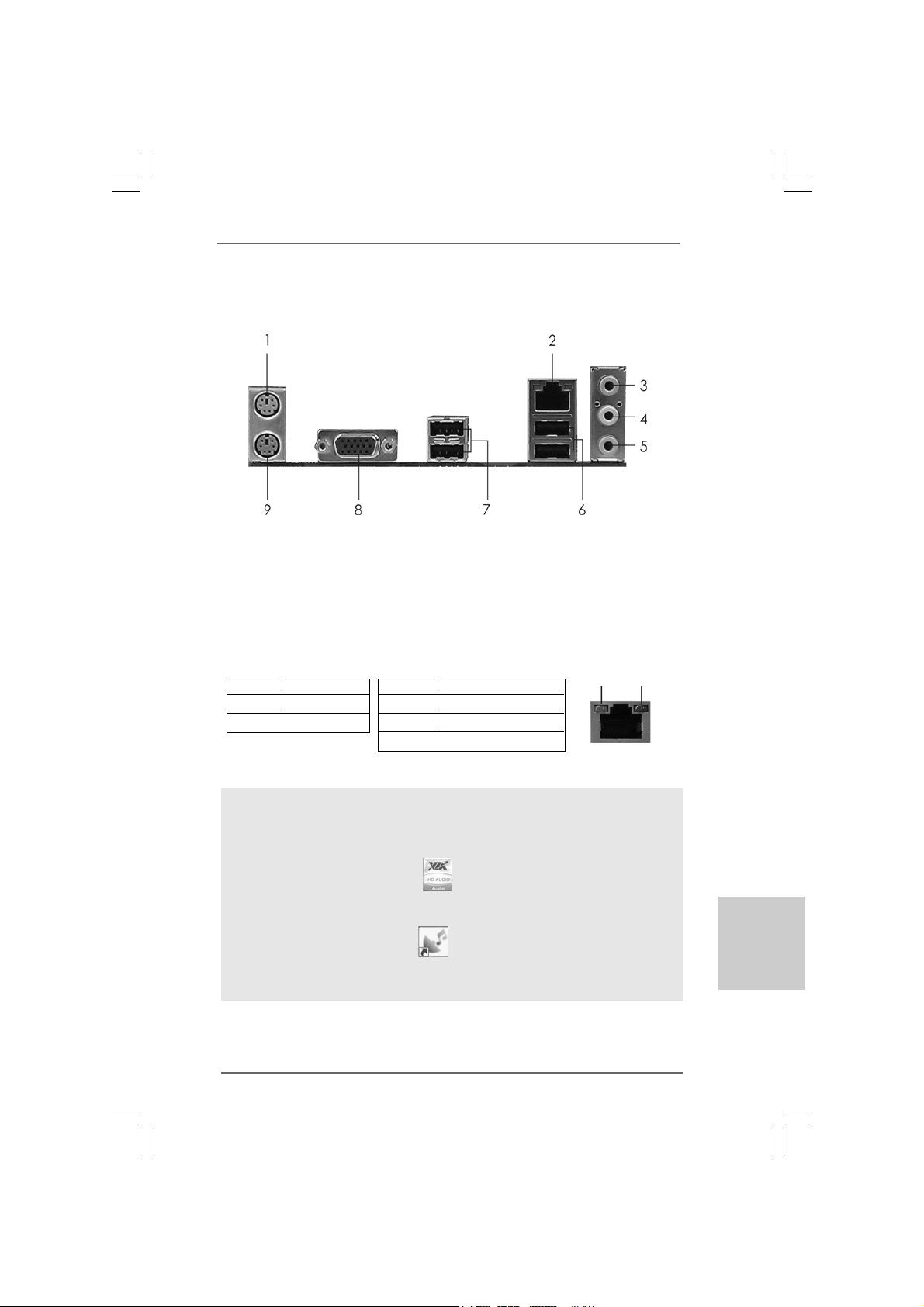
I/O PI/O P
I/O PI/O P
I/O P
anel (G41M-anel (G41M-
anel (G41M-anel (G41M-
anel (G41M-
VGS3)VGS3)
VGS3)VGS3)
VGS3)
To enable Multi-Streaming function, you need to connect a front panel audio cable to the front
panel audio header. After restarting your computer, you will find “VIA HD Audio Deck” tool on
your system. Please follow below instructions according to the OS you install.
For Windows
®
XP / XP 64-bit OS:
Please click “VIA HD Audio Deck” icon , and click “Speaker”. Then you are allowed to
select “2 Channel” or “4 Channel”. Click “Power” to save your change.
For Windows
®
7 / 7 64-bit / Vista
TM
/ Vista
TM
64-bit OS:
Please click “VIA HD Audio Deck” icon , and click “Advanced Options” on the left side
on the bottom. In “Advanced Options” screen, select “Independent Headphone”, and click
“OK” to save your change.
LAN Port LED Indications
Activity/Link LED SPEED LED
Status Description Status Description
Off No Activity Off 10Mbps connection
Blinking Data Activity Orange 100Mbps connection
Green 1Gbps connection
LAN Port
ACT/LINK
LED
SPEED
LED
1 PS/2 Mouse Port (Green) 6 USB 2.0 Ports (USB01)
* 2 RJ-45 Port 7 USB 2.0 Ports (USB23)
3 Line In (Light Blue) 8 VGA Port
4 Line Out (Lime) 9 PS/2 Keyboard Port (Purple)
5 Microphone (Pink)
44
44
4
ASRock G41M-VGS3 / G41M-VS3 Motherboard
EnglishEnglish
EnglishEnglish
English
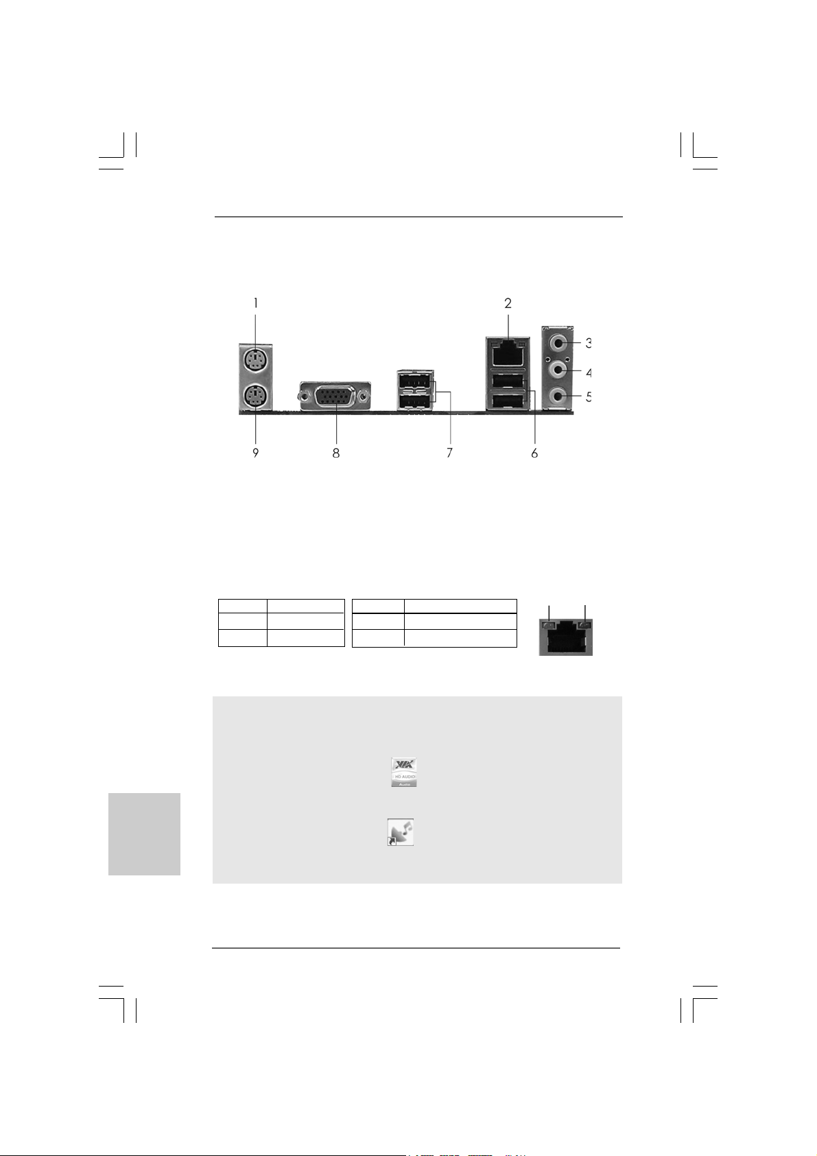
I/O PI/O P
I/O PI/O P
I/O P
anel (G41M-anel (G41M-
anel (G41M-anel (G41M-
anel (G41M-
VS3)VS3)
VS3)VS3)
VS3)
To enable Multi-Streaming function, you need to connect a front panel audio cable to the front
panel audio header. After restarting your computer, you will find “VIA HD Audio Deck” tool on
your system. Please follow below instructions according to the OS you install.
For Windows
®
XP / XP 64-bit OS:
Please click “VIA HD Audio Deck” icon , and click “Speaker”. Then you are allowed to
select “2 Channel” or “4 Channel”. Click “Power” to save your change.
For Windows
®
7 / 7 64-bit / Vista
TM
/ Vista
TM
64-bit OS:
Please click “VIA HD Audio Deck” icon , and click “Advanced Options” on the left side
on the bottom. In “Advanced Options” screen, select “Independent Headphone”, and click
“OK” to save your change.
LAN Port LED Indications
Activity/Link LED SPEED LED
Status Description Status Description
Off No Activity Off 10Mbps connection
Blinking Data Activity Green 100Mbps connection
LAN Port
ACT/LINK
LED
SPEED
LED
1 PS/2 Mouse Port (Green) 6 USB 2.0 Ports (USB01)
* 2 RJ-45 Port 7 USB 2.0 Ports (USB23)
3 Line In (Light Blue) 8 VGA Port
4 Line Out (Lime) 9 PS/2 Keyboard Port (Purple)
5 Microphone (Pink)
55
55
5
ASRock G41M-VGS3 / G41M-VS3 Motherboard
1. Introduction1. Introduction
1. Introduction1. Introduction
1. Introduction
Thank you for purchasing ASRock G41M-VGS3 / G41M-VS3 motherboard, a reli-
able motherboard produced under ASRock’s consistently stringent quality control. It
delivers excellent performance with robust design conforming to ASRock’s commit-
ment to quality and endurance.
This Quick Installation Guide contains introduction of the motherboard and step-by-
step installation guide. More detailed information of the motherboard can be found in
the user manual presented in the Support CD.
Because the motherboard specifications and the BIOS software might
be updated, the content of this manual will be subject to change without
notice. In case any modifications of this manual occur, the updated
version will be available on ASRock website without further notice. You
may find the latest VGA cards and CPU support lists on ASRock website
as well. ASRock website http://www.asrock.com
If you require technical support related to this motherboard, please visit
our website for specific information about the model you are using.
www.asrock.com/support/index.asp
1.1 Package Contents1.1 Package Contents
1.1 Package Contents1.1 Package Contents
1.1 Package Contents
ASRock G41M-VGS3 / G41M-VS3 Motherboard
(Micro ATX Form Factor: 8.9-in x 6.7-in, 22.6 cm x 17.0 cm)
ASRock G41M-VGS3 / G41M-VS3 Quick Installation Guide
ASRock G41M-VGS3 / G41M-VS3 Support CD
Two Serial ATA (SATA) Data Cables (Optional)
One I/O Panel Shield
EnglishEnglish
EnglishEnglish
English
66
66
6
ASRock G41M-VGS3 / G41M-VS3 Motherboard
EnglishEnglish
EnglishEnglish
English
1.21.2
1.21.2
1.2
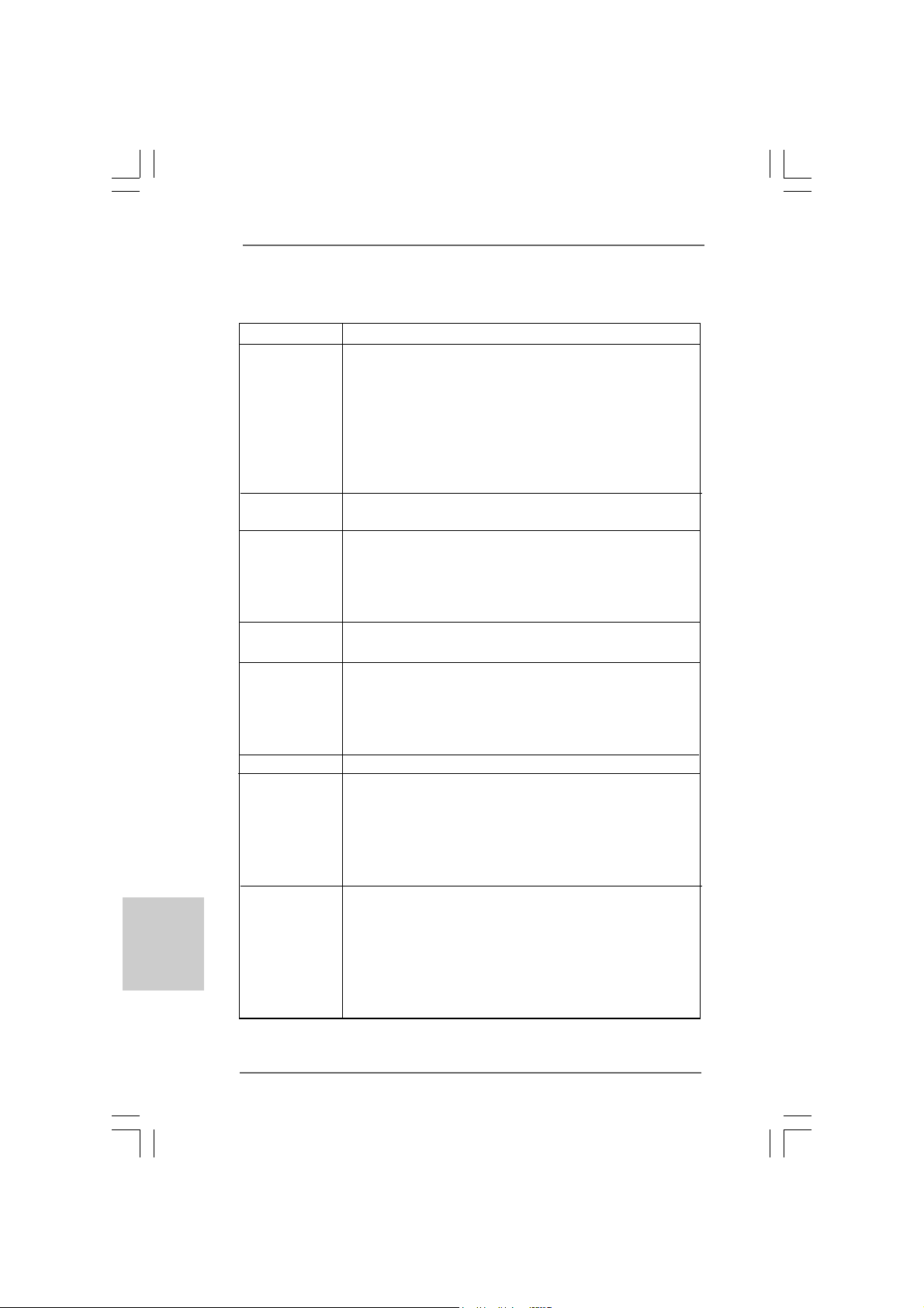
SpecificationsSpecifications
SpecificationsSpecifications
Specifications
Platform - Micro ATX Form Factor: 8.9-in x 6.7-in, 22.6 cm x 17.0 cm
CPU - LGA 775 for Intel
®
Core
TM
2 Extreme / Core
TM
2 Quad / Core
TM
2 Duo / Pentium
®
Dual Core / Celeron
®
Dual Core / Celeron
®
,
supporting Penryn Quad Core Yorkfield and Dual Core
Wolfdale processors
- Supports FSB1333/1066/800/533 MHz
- Supports Hyper-Threading Technology (see CAUTION 1)
- Supports Untied Overclocking Technology (see CAUTION 2)
- Supports EM64T CPU
Chipset - Northbridge: Intel
®
G41
- Southbridge: Intel
®
ICH7
Memory - Dual Channel DDR3 Memory T echnology (see CAUTION 3)
- 2 x DDR3 DIMM slots
- Supports DDR3 1333(OC)/1066/800 non-ECC, un-buffered
memory (see CAUTION 4)
- Max. capacity of system memory: 8GB (see CAUTION 5)
Expansion Slot - 1 x PCI Express x16 slot
- 1 x PCI slot
Graphics - Intel
®
Graphics Media Accelerator X4500
- Pixel Shader 4.0, DirectX 10
- Max. shared memory 1759MB (see CAUTION 6)
- Supports D-Sub with max. resolution up to 2048x1536 @
75Hz
Audio - 5.1 CH HD Audio (VIA
®
VT1705 Audio Codec)
LAN - G41M-VGS3
Atheros
®
PCIE x1 Gigabit LAN AR8151,
speed 10/100/1000 Mb/s
- G41M-VS3
Atheros
®
PCIE x1 LAN AR8152, speed 10/100 Mb/s
- Supports Wake-On-LAN
Rear Panel I/O I/O Panel
- 1 x PS/2 Mouse Port
- 1 x PS/2 Keyboard Port
- 1 x VGA Port
- 4 x Ready-to-Use USB 2.0 Ports
- 1 x RJ-45 LAN Port with LED (ACT/LINK LED and SPEED LED)
- HD Audio Jack: Line in / Front Speaker / Microphone
77
77
7
ASRock G41M-VGS3 / G41M-VS3 Motherboard
EnglishEnglish
EnglishEnglish
English
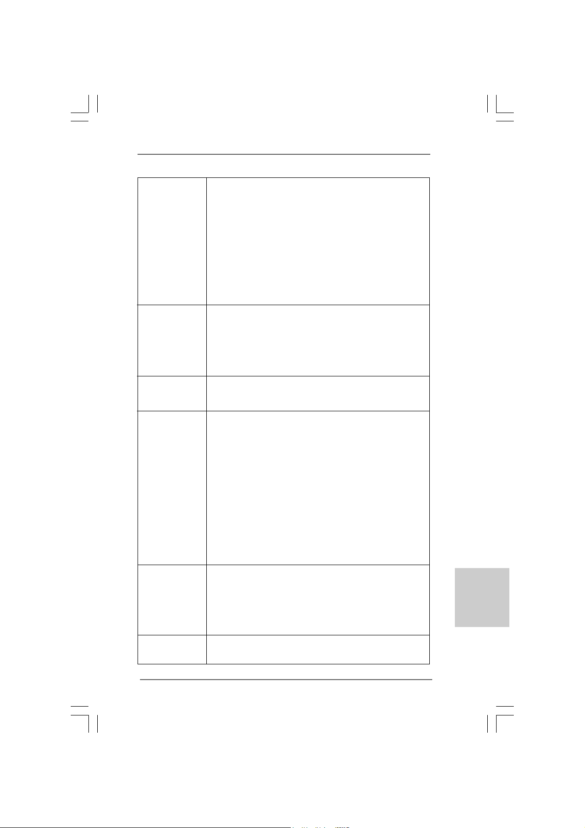
Connector - 4 x SATAII 3.0 Gb/s connectors (No Support for RAID and
“Hot Plug” functions) (see CAUTION 7)
- 1 x ATA100 IDE connector (supports 2 x IDE devices)
- 1 x Print port header
- 1 x COM port header
- CPU/Chassis FAN connector
- 24 pin ATX power connector
- 4 pin 12V power connector
- Front panel audio connector
- 2 x USB 2.0 headers (support 4 USB 2.0 ports)
(see CAUTION 8)
BIOS Feature - 8Mb AMI BIOS
- AMI Legal BIOS
- Supports “Plug and Play”
- ACPI 1.1 Compliance Wake Up Events
- AMBIOS 2.3.1 Support
- VCCM, NB, VTT , GTLRef V oltage Multi-adjustment
Support CD - Drivers, Utilities, AntiVirus Software (Trial Version),
ASRock Software Suite (CyberLink DVD Suite - OEM and
Trial; Creative Sound Blaster X-Fi MB - Trial)
Unique Feature - ASRock OC Tuner (see CAUTION 9)
- Intelligent Energy Saver (see CAUTION 10)
- Instant Boot
- ASRock Instant Flash (see CAUTION 11)
- ASRock OC DNA (see CAUTION 12)
- ASRock AIWI (see CAUTION 13)
- ASRock APP Charger (see CAUTION 14)
- SmartView (see CAUTION 15)
- ASRock XFast USB (see CAUTION 16)
- Hybrid Booster:
- CPU Frequency Stepless Control (see CAUTION 17)
- ASRock U-COP (see CAUTION 18)
- Boot Failure Guard (B.F.G.)
Hardware - CPU Temperature Sensing
Monitor - Chassis Temperature Sensing
- CPU Fan Tachometer
- Chassis Fan Tachometer
- CPU Quiet Fan
- Voltage Monitoring: +12V, +5V, +3.3V, Vcore
OS - Microsoft
®
Windows
®
7 / 7 64-bit / Vista
TM
/ Vista
TM
64-bit / XP
/ XP 64-bit compliant

88
88
8
ASRock G41M-VGS3 / G41M-VS3 Motherboard
EnglishEnglish
EnglishEnglish
English
CAUTION!
1. About the setting of “Hyper Threading Technology”, please check page 34
of “User Manual” in the support CD.
2. This motherboard supports Untied Overclocking Technology. Please read
“Untied Overclocking Technology” on page 21 for details.
3. This motherboard supports Dual Channel Memory Te chnology. Before you
implement Dual Channel Memory Technology, make sure to read the
installation guide of memory modules on page 14 for proper installation.
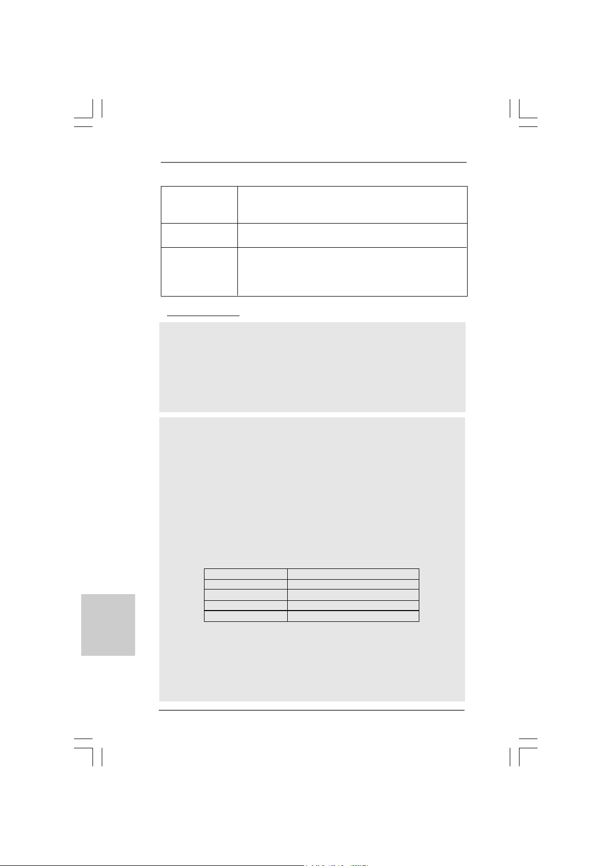
4. Please check the table below for the CPU FSB frequency and its
corresponding memory support frequency.
CPU FSB Frequency Memory Support Frequency
1333 DDR3 800, DDR3 1066, DDR3 1333
1066 DDR3 800, DDR3 1066
800 DDR3 800
533 DDR3 800
* DDR3 1333 memory modules will operate in overclocking mode.
* When you use a FSB533-CPU on this motherboard, it will run at
DDR3 533 if you adopt a DDR3 800 memory module.
* If you adopt FSB1333-CPU and DDR3 1333 memory module on this
motherboard, you need to adjust the jumper. Please refer to page 17 for
proper jumper settings.
5. Due to the operating system limitation, the actual memory size may be
less than 4GB for the reservation for system usage under Windows
®
7 /
Vista
TM
/ XP. For Windows
®
OS with 64-bit CPU, there is no such limitation.
6. The maximum shared memory size is defined by the chipset vendor and
is subject to change. Please check Intel
®
website for the latest information.
7. Before installing SATAII hard disk to SAT AII connector, please rea d the “SAT AII
Hard Disk Setup Guide” on page 24 of “User Manual” in the support CD to
adjust your SATAII hard disk drive to SATAII mode. You can also connect SAT A
hard disk to SATAII connector directly.
8. Power Management for USB 2.0 works fine under Microsoft
®
Windows
®
7
64-bit / 7 / Vista
TM
64-bit / Vista
TM
/ XP 64-bit / XP SP1 or SP2.
WARNING
Please realize that there is a certain risk involved with overclocking, including adjusting
the setting in the BIOS, applying Untied Overclocking Technology, or using the third-
party overclocking tools. Overclocking may affect your system stability, or even
cause damage to the components and devices of your system. It should be done at
your own risk and expense. We are not responsible for possible damage caused by
overclocking.
Certifications - FCC, CE, WHQL
- ErP/EuP Ready (ErP/EuP ready power supply is required)
(see CAUTION 19)
* For detailed product information, please visit our website: http://www.asrock.com
99
99
9
ASRock G41M-VGS3 / G41M-VS3 Motherboard
EnglishEnglish
EnglishEnglish
English
9. It is a user-friendly ASRock overclocking tool which allows you to surveil
your system by hardware monitor function and overclock your hardware
devices to get the best system performance under Windows
®
environment.
Please visit our website for the operation procedures of ASRock OC
Tuner. ASRock website: http://www.asrock.com
10. Featuring an advanced proprietary hardware and software design,
Intelligent Energy Saver is a revolutionary technology that delivers
unparalleled power savings. In other words, it is able to provide exceptional
power saving and improve power efficiency without sacrificing computing
performance. Please visit our website for the operation procedures of
Intelligent Energy Saver.
ASRock website: http://www.asrock.com
11. ASRock Instant Flash is a BIOS flash utility embedded in Flash ROM.
This convenient BIOS update tool allows you to update system BIOS
without entering operating systems first like MS-DOS or Windows
®
. With
this utility, you can press <F6> key during the POST or press <F2> key to
BIOS setup menu to access ASRock Instant Flash. Just launch this tool
and save the new BIOS file to your USB flash drive, floppy disk or hard
drive, then you can update your BIOS only in a few clicks without prepar-
ing an additional floppy diskette or other complicated flash utility. Please
be noted that the USB flash drive or hard drive must use FAT32/16/12 file
system.
12. The software name itself – OC DNA literally tells you what it is capable of.
OC DNA, an exclusive utility developed by ASRock, provides a conve-
nient way for the user to record the OC settings and share with others. It
helps you to save your overclocking record under the operating system
and simplifies the complicated recording process of overclocking settings.
With OC DNA, you can save your OC settings as a profile and share with
your friends! Your friends then can load the OC profile to their own system
to get the same OC settings as yours! Please be noticed that the OC
profile can only be shared and worked on the same motherboard.
13. To experience intuitive motion controlled games is no longer only available
at Wii. ASRock AIWI utility introduces a new way of PC gaming operation.
ASRock AIWI is the world's first utility to turn your iPhone/iPod touch as
a game joystick to control your PC games. All you have to do is just to
install the ASRock AIWI utility either from ASRock official website or
ASRock software support CD to your motherboard, and also download the
free AIWI Lite from App store to your iPhone/iPod touch. Connecting your
PC and apple devices via Bluetooth or WiFi networks, then you can start
experiencing the exciting motion controlled games. Also, please do not
forget to pay attention to ASRock official website regularly, we will
continuously provide you the most up-do-date supported games!
ASRock website: http://www.asrock.com/Feature/Aiwi/index.asp
1010
1010
10
ASRock G41M-VGS3 / G41M-VS3 Motherboard
14. If you desire a faster, less restricted way of charging your Apple devices,
such as iPhone/iPod/iPad Touch, ASRock has prepared a wonderful
solution for you - ASRock APP Charger. Simply installing the APP Charger
driver, it makes your iPhone charged much quickly from your computer
and up to 40% faster than before. ASRock APP Charger allows you to
quickly charge many Apple devices simultaneously and even supports
continuous charging when your PC enters into Standby mode (S1), Sus-
pend to RAM (S3), hibernation mode (S4) or power off (S5). With APP
Charger driver installed, you can easily enjoy the marvelous charging
experience than ever.
ASRock website: http://www.asrock.com/Feature/AppCharger/index.asp
15. SmartView, a new function of internet browser, is the smart start page for
IE that combines your most visited web sites, your history, your Facebook
friends and your real-time newsfeed into an enhanced view for a more
personal Internet experience. ASRock motherboards are exclusively
equipped with the SmartView utility that helps you keep in touch with
friends on-the-go. To use SmartView feature, please make sure your OS
version is Windows
®
7 / 7 64 bit / Vista
TM
/ Vista
TM
64 bit, and your browser
version is IE8.
ASRock website: http://www.asrock.com/Feature/SmartView/index.asp
16. ASRock XFast USB can boost USB storage device performance. The
performance may depend on the property of the device.
17. Although this motherboard offers stepless control, it is not recommended
to perform over-clocking. Frequencies other than the recommended CPU
bus frequencies may cause the instability of the system or damage the
CPU.
18. While CPU overheat is detected, the system will automatically shutdown.
Before you resume the system, please check if the CPU fan on the
motherboard functions properly and unplug the power cord, then plug it
back again. To improve heat dissipation, remember to spray thermal
grease between the CPU a nd the he atsink when you in stall the PC system.
19. EuP, stands for Energy Using Product, was a provision regulated by
European Union to define the power consumption for the completed system.
According to EuP, the total AC power of the completed system shall be
under 1.00W in off mode condition. To meet EuP standard, an EuP ready
motherboard and an EuP ready power supply are required. According to
Intel’s suggestion, the EuP ready power supply must meet the standard of
5v standby power efficiency is higher than 50% under 100 mA current
consumption. For EuP ready power supply selection, we recommend you
checking with the power supply manufacturer for more details.
EnglishEnglish
EnglishEnglish
English
1111
1111
11
ASRock G41M-VGS3 / G41M-VS3 Motherboard
EnglishEnglish
EnglishEnglish
English
2.2.
2.2.
2.
InstallationInstallation
InstallationInstallation
Installation
Pre-installation PrecautionsPre-installation Precautions
Pre-installation PrecautionsPre-installation Precautions
Pre-installation Precautions
Take note of the following precautions before you install mother-
board components or change any motherboard settings.
1. Unplug the power cord from the wall socket before touching any
component. Failure to do so may cause severe damage to the
motherboard, peripherals, and/or components.
2. To avoid damaging the motherboard components due to static
electricity, NEVER place your motherboard directly on the carpet
or the like. Also remember to use a grounded wrist strap or touch
a safety grounded object before you handle components.
3. Hold components by the edges and do not touch the ICs.
4. Whenever you uninstall any component, place it on a grounded
antstatic pad or in the bag that comes with the component.
5. When placing screws into the screw holes to secure the
motherboard to the chassis, please do not over-tighten the
screws! Doing so may damage the motherboard.
2.12.1
2.12.1
2.1
CPU InstallationCPU Installation
CPU InstallationCPU Installation
CPU Installation
For the installation of Intel 775-LAND CPU,
please follow the steps below.
Before you insert the 775-LAND CPU into the socket, please check if
the CPU surface is unclean or if there is any bent pin on the socket.
Do not force to insert the CPU into the socket if above situation is
found. Otherwise, the CPU will be seriously damaged.
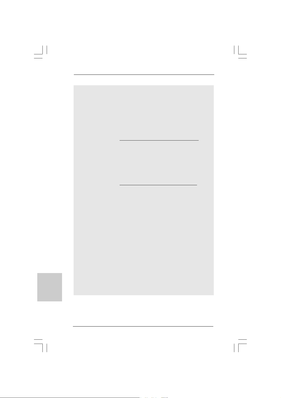
775-Pin Socket Overview
1212
1212
12
ASRock G41M-VGS3 / G41M-VS3 Motherboard
EnglishEnglish
EnglishEnglish
English
Step 1. Open the socket:
Step 1-1. Disengaging the lever by depressing
down and out on the hook to clear
retention tab.
Step 1-2. Rotate the load lever to fully open po-
sition at approximately 135 degrees.
Step 1-3. Rotate the load plate to fully open po-
sition at approximately 100 degrees.
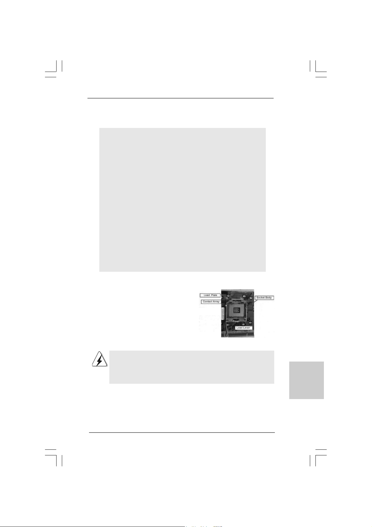
Step 2. Insert the 775-LAND CPU:
Step 2-1. Hold the CPU by the edges where are
marked with black lines.
Step 2-2. Orient the CPU with IHS (Integrated
Heat Sink) up. Locate Pin1 and the two
orientation key notches.
For proper inserting, please ensure to match the two orientation key
notches of the CPU with the two alignment keys of the socket.
Step 2-3. Carefully pla ce the CPU into the socket
by using a purely vertical motion.
Step 2-4. Verify that the CPU is within the socket
and properly mated to the orient keys.
Step 3. Remove PnP Cap (Pick and Pla ce Cap):
Use your left hand index finger and thumb to
support the load plate edge, engage PnP cap
with right hand thumb and peel the cap from the
socket while pressing on center of PnP cap to
assist in removal.
black line
black line
775-Pin Socket
Pin1
alignment key
alignment key
Pin1
orientation
key notch
orientation
key notch
775-LAND CPU
1313
1313
13
ASRock G41M-VGS3 / G41M-VS3 Motherboard
EnglishEnglish
EnglishEnglish
English
1. It is recommended to use the cap tab to handle and avoid kicking
off the PnP cap.
2. This cap must be placed if returning the motherboard for after
service.
Step 4. Close the socket:
Step 4-1. Rotate the load plate onto the IHS.
Step 4-2. While pressing down lightly on load
plate, engage the load lever.
Step 4-3. Secure load lever with load plate tab
under retention tab of load lever.
2.22.2
2.22.2
2.2
Installation of CPU Fan and HeatsinkInstallation of CPU Fan and Heatsink
Installation of CPU Fan and HeatsinkInstallation of CPU Fan and Heatsink
Installation of CPU Fan and Heatsink
For proper installation, please kindly refer to the instruction manuals of your CPU fan
and heatsink.
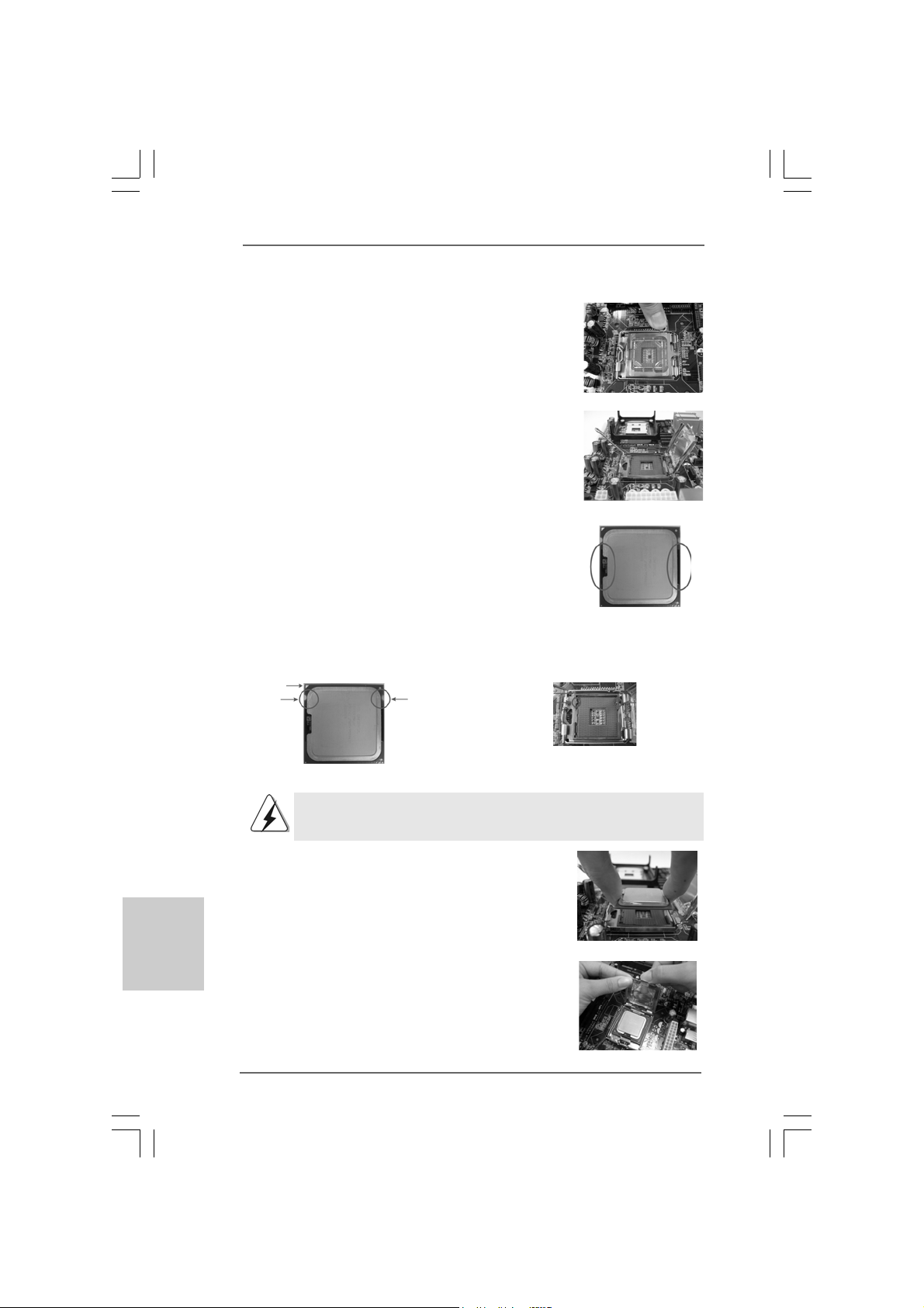
Below is an example to illustrate the installation of the heatsink for 775-LAND CPU.
Step 1. Apply thermal interface material onto center
of IHS on the socket surface.
Step 2. Place the heatsink onto the socket. Ensure
fan cables are oriented on side closest to the
CPU fan connector on the motherboard
(CPU_FAN1, see page 2, No. 3).
Step 3. Align fasteners with the motherboard
throughholes.
Step 4. Rotate the fastener clockwise, then press
down on fastener caps with thumb to install
and lock. Repeat with remaining fasteners.
If you press down the fasteners without rotating them clockwise,
the heatsink cannot be secured on the motherboard.
Step 5. Connect fan header with the CPU fan
connector on the motherboard.
Step 6. Secure excess cable with tie-wrap to ensure
cable does not interfere with fan operation or
contact other components.
1414
1414
14
ASRock G41M-VGS3 / G41M-VS3 Motherboard
EnglishEnglish
EnglishEnglish
English
2.3 Installation of Memory Modules (DIMM)2.3 Installation of Memory Modules (DIMM)
2.3 Installation of Memory Modules (DIMM)2.3 Installation of Memory Modules (DIMM)
2.3 Installation of Memory Modules (DIMM)
G41M-VGS3 / G41M-VS3 motherboard provides two 240-pin DDR3 (Double Data
Rate 3) DIMM slots, and supports Dual Channel Memory Te chnology. For dual channel
configuration, you always need to install two identical (the same brand, speed,
size and chip-type) memory modules in the DDR3 DIMM slots to activate Dual Channel
Memory Technology. Otherwise, it will operate at single channel mode.
1. It is not allowed to install a DDR or DDR2 memory module into
DDR3 slot;otherwise, this motherboard and DIMM may be damaged.
2. If you install only one memory module or two non-identical memory
modules, it is unable to activate the Dual Cha nnel Memory Technology.
Installing a DIMMInstalling a DIMM
Installing a DIMMInstalling a DIMM
Installing a DIMM
Please make sure to disconnect power supply before adding or
removing DIMMs or the system components.
Step 1. Unlock a DIMM slot by pressing the retaining clips outward.
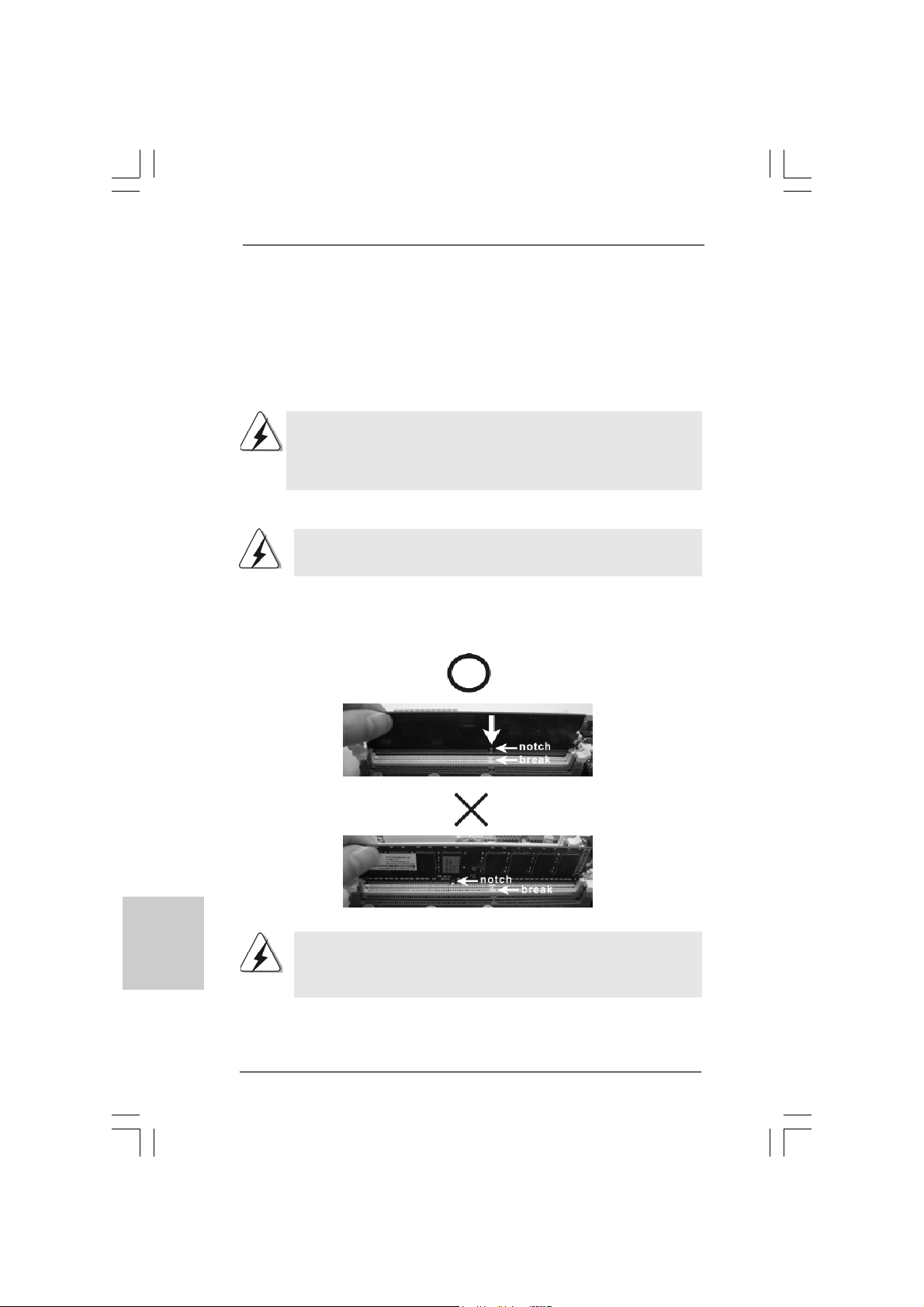
Step 2. Align a DIMM on the slot such that the notch on the DIMM matches the brea k
on the slot.
The DIMM only fits in one correct orientation. It will cause permanent
damage to the motherboard and the DIMM if you force the DIMM into the
slot at incorrect orientation.
Step 3. Firmly insert the DIMM into the slot until the retaining clips at both ends fully
snap back in place and the DIMM is properly seated.
1515
1515
15
ASRock G41M-VGS3 / G41M-VS3 Motherboard
EnglishEnglish
EnglishEnglish
English
2.4 Expansion Slots (PCI and PCI Express Slots)2.4 Expansion Slots (PCI and PCI Express Slots)
2.4 Expansion Slots (PCI and PCI Express Slots)2.4 Expansion Slots (PCI and PCI Express Slots)
2.4 Expansion Slots (PCI and PCI Express Slots)
There are 1 PCI slot and 1 PCI Express slot on this motherboard.
PCI slot: PCI slot is used to install expansion cards that have the 32-bit PCI
interface.
PCIE slot:
PCIE1 (PCIE x16 slot) is used for PCI Express cards with x16 lane
width graphics cards.
If you install the add-on PCI Express VGA card to PCIE1 (PCIE x16 slot),
the onboard VGA will be disabled. If you install the add-on PCI Express
VGA card to PCIE1 (PCIE x16 slot) and adjust the BIOS options “Primary
Graphics Adapter” to [Onboard] and “Share Memory” to [Auto], then the
onboard VGA will be enabled, and the primary screen will be onboard
VGA.
Installing an expansion cardInstalling an expansion card
Installing an expansion cardInstalling an expansion card
Installing an expansion card
Step 1. Before installing the expansion card, please make sure that the power
supply is switched off or the power cord is unplugged. Please read the
documentation of the expansion card and make necessary hardware
settings for the card before you start the installation.
Step 2. Remove the bracket facing the slot that you intend to use. Keep the screws
for later use.
Step 3. Align the card connector with the slot and press firmly until the card is
completely seated on the slot.
Step 4. Fasten the card to the chassis with screws.
1616
1616
16
ASRock G41M-VGS3 / G41M-VS3 Motherboard
EnglishEnglish
EnglishEnglish
English
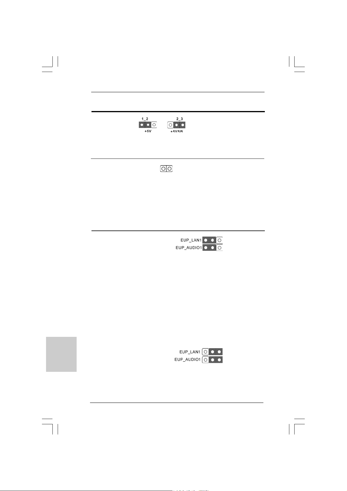
2.5 Jumpers Setup2.5 Jumpers Setup
2.5 Jumpers Setup2.5 Jumpers Setup
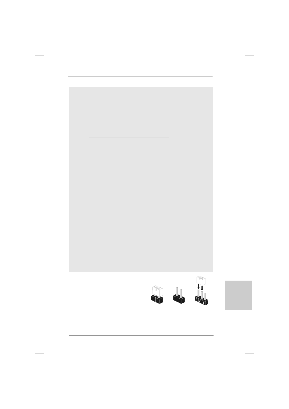
2.5 Jumpers Setup
The illustration shows how jumpers are
setup. When the jumper cap is placed on
pins, the jumper is “Short”. If no jumper cap
is placed on pins, the jumper is “Open”. The
illustration shows a 3-pin jumper whose pin1
and pin2 are “Short” when jumper cap is
placed on these 2 pins.
Jumper Setting Description
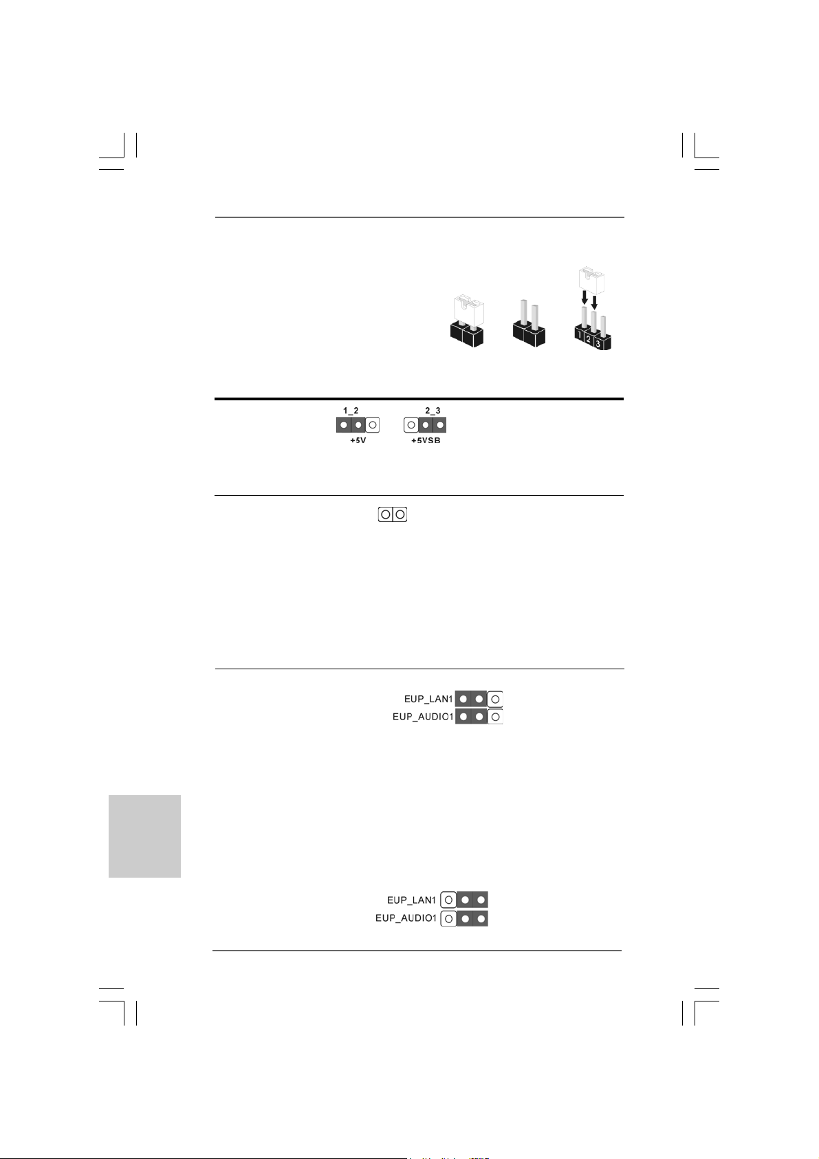
PS2_USB_PWR1 Short pin2, pin3 to enable
(see p.2 No. 1) +5VSB (standby) for PS/2
or USB wake up events.
Note: To select +5VSB, it requires 2 Amp and higher standby current provided by
power supply.
Clear CMOS
(CLRCMOS1, 2-pin jumper)
(see p.2 No. 18)
Note: CLRCMOS1 allows you to clear the data in CMOS. The data in CMOS includes
system setup information such as system password, date, time, and system
setup parameters. To clear and reset the system parameters to default setup,
please turn off the computer and unplug the power cord from the power
supply. After waiting for 15 seconds, use a jumper cap to short 2 pins on
CLRCMOS1 for 5 seconds.
2-pin jumper
Short Open
EUP LAN / EUP Audio Jumper
(EUP_LAN1, 3-pin jumper, see p.2 No. 23)
(EUP_AUDIO1, 3-pin jumper, see p.2 No. 22)
Note: EUP_LAN and EUP_AUDIO jumper design decreases the power consumption
of this motherboard to meet EuP standard. With an ASRock EuP ready
motherboard and a power supply that the 5VSB power efficiency is higher
than 50% under 100mA current consumption, your system is able to submit
EuP standard. The default setting (short pin1 and pin2) is EuP enabled. If you
want to disable this power saving function, you may short pin2 and pin3.
Please be noticed that when EUP_LAN jumper is set to enabled, the
Wake-On-LAN function under S3 (Suspend to RAM), S4 (Suspend to Disk),
and S5 (Soft Off) will be disabled.
Default (Enable EuP)
(Disable EuP)
1717
1717
17
ASRock G41M-VGS3 / G41M-VS3 Motherboard
EnglishEnglish
EnglishEnglish
English
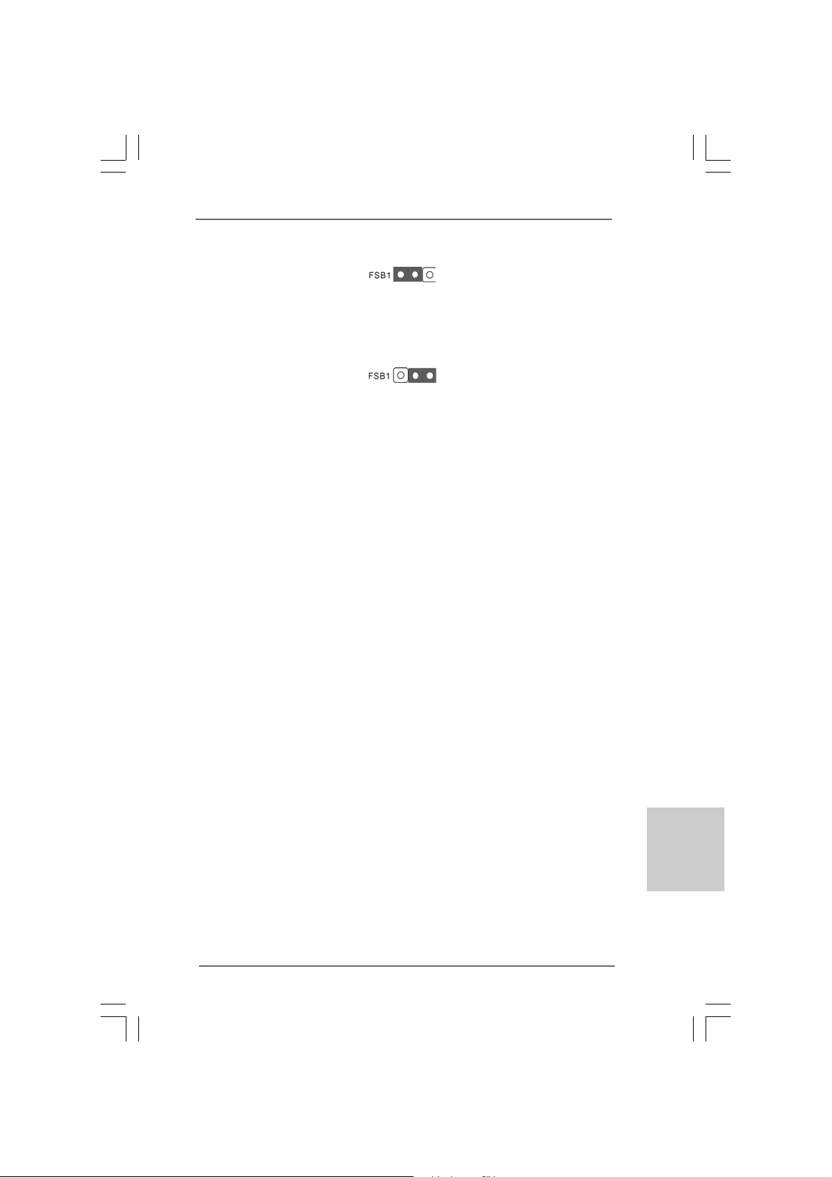
FSB1 Jumper
(FSB1, 3-pin jumper, see p.2 No. 27)
If you adopt FSB1333-CPU and D DR3 1333 memory module on this motherboard, you
need to adjust the jumper. Please short pin2, pin3 for FSB1 jumper. Otherwise, the
CPU and memory module may not work properly on this motherboard. Please refer to
below jumper setting.
Default
1818
1818
18
ASRock G41M-VGS3 / G41M-VS3 Motherboard
EnglishEnglish
EnglishEnglish
English
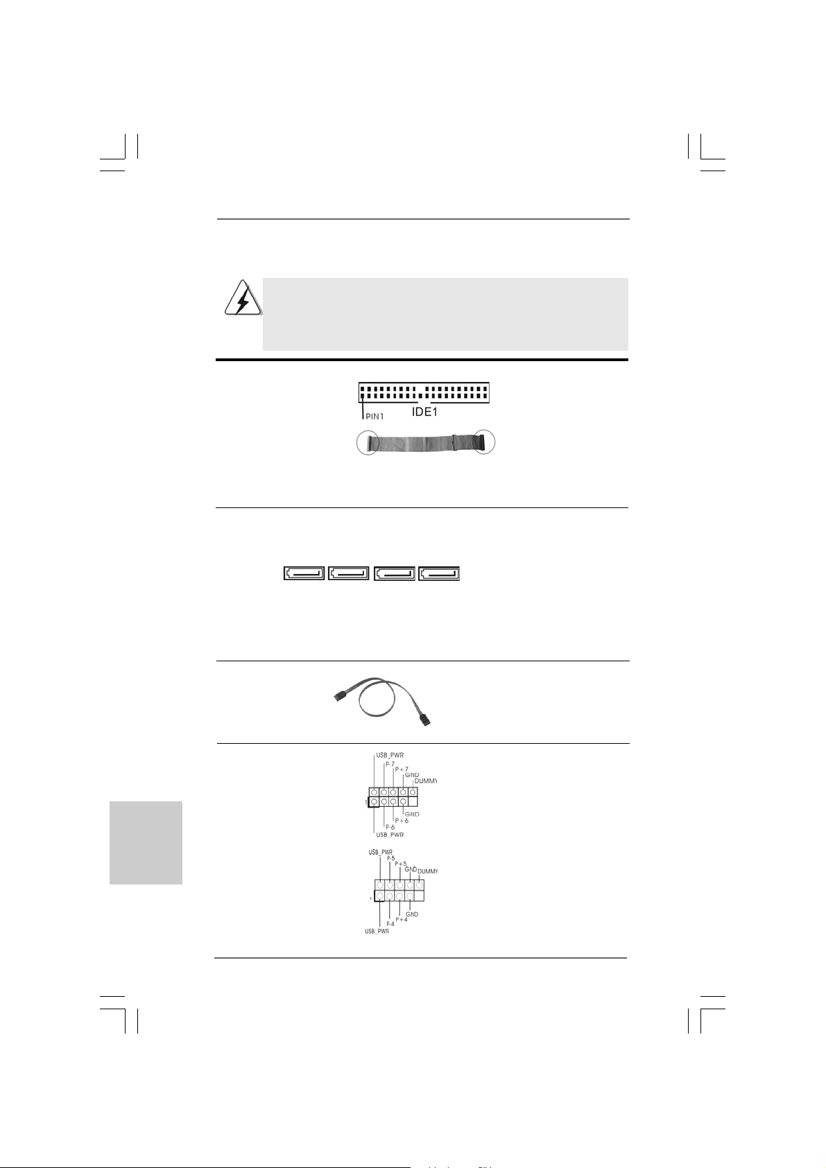
USB 2.0 Headers Besides four default USB 2.0
(9-pin USB6_7) ports on the I/O panel, there are
(see p.2 No. 17) two USB 2.0 headers on this
motherboard. Each USB 2.0
header cansupport two USB
2.0 ports.
(9-pin USB4_5)
(see p.2 No. 15)
2.6 Onboard Headers and Connectors2.6 Onboard Headers and Connectors
2.6 Onboard Headers and Connectors2.6 Onboard Headers and Connectors
2.6 Onboard Headers and Connectors
Onboard headers and connectors are NOT jumpers. Do NOT place
jumper caps over these headers and connectors. Placing jumper caps
over the headers and connectors will cause permanent damage of the
motherboard!
Primary IDE connector (Blue)
(39-pin IDE1, see p.2 No. 9)
Note: Please refer to the instruction of your IDE device vendor for the details.
Serial A T AII Connectors These Serial A T AII (SA TAII)
(SAT AII_1: connectors support SATAII
see p.2, No. 10) or SATA hard disk for internal
(SAT AII_2: storage devices. The current
see p.2, No. 1 1) SATAII interface allows up to
(SAT AII_3: 3.0 Gb/s data transfer rate.
see p.2, No. 12)
(SAT AII_4:
see p.2, No. 13)
Serial A TA (SA TA) Either end of the SATA data cable
Data Cable can be connected to the SATA /
(Optional) SATAII hard disk or the SATAII
connector on the motherboard.
connect the black end
to the IDE devices
connect the blue end
to the motherboard
80-conductor ATA 66/100 cable
SAT AII_2 SA T AII_1
SAT AII_4 SA T AII_3
1919
1919
19
ASRock G41M-VGS3 / G41M-VS3 Motherboard
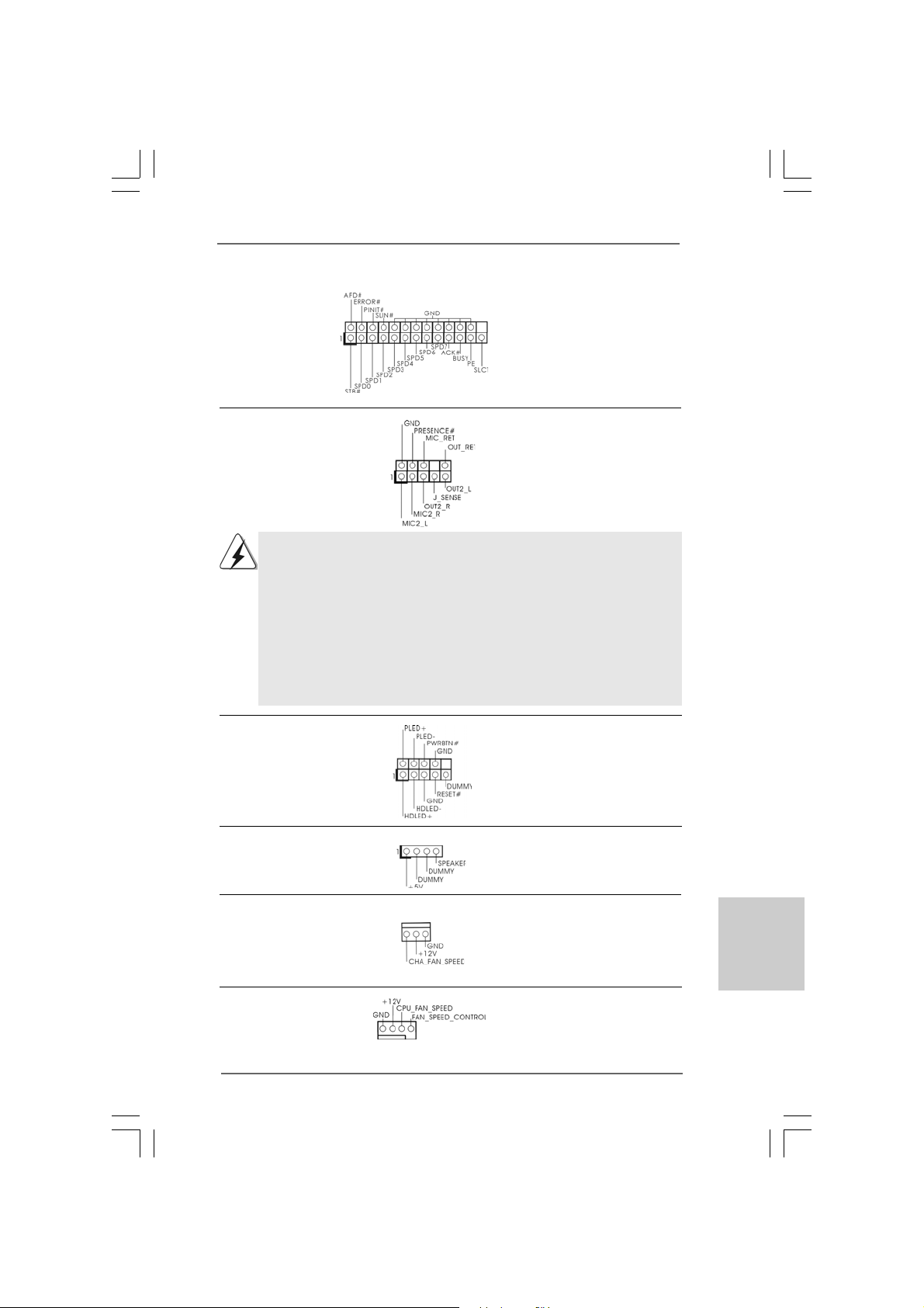
1. High Definition Audio supports Jack Sensing, but the panel wire on
the chassis must support HDA to function correctly. Please follow the
instruction in our manual and chassis manual to install your system.
2. If you use AC’97 audio panel, please install it to the front panel audio
header as below:
A. Connect Mic_IN (MIC) to MIC2_L.
B. Connect Audio_R (RIN) to OUT2_R and Audio_L (LIN) to OUT2_L.
C. Connect Ground (GND) to Ground (GND).
D. MIC_RET and OUT_RET are for HD audio panel only. You don’t
need to connect them for AC’97 audio panel.
Print Port Header This is an interface for print
(25-pin LPT1) port cable that allows
(see p.2 No. 26) convenient connection of printer
devices.
Front Panel Audio Header This is an interface for front
(9-pin HD_AUDIO1) panel audio cable that allows
(see p.2 No. 24) convenient connection and
control of audio devices.
EnglishEnglish
EnglishEnglish
English
System Panel Header This header accommodates
(9-pin PANEL1) several system front panel
(see p.2 No. 8) functions.
Chassis Speaker Header Please connect the chassis
(4-pin SPEAKER 1) speaker to this header.
(see p.2 No. 14)
Chassis Fan Connector Please connect a chassis fan
(3-pin CHA_FAN1) cable to this connector and
(see p.2 No. 16) match the black wire to the
ground pin.
CPU Fan Connector Please connect a CPU fan cable
(4-pin CPU_FAN1) to this connector and match
(see p.2 No. 3) the black wire to the ground pin.
1 2 3 4
2020
2020
20
ASRock G41M-VGS3 / G41M-VS3 Motherboard
EnglishEnglish
EnglishEnglish
English
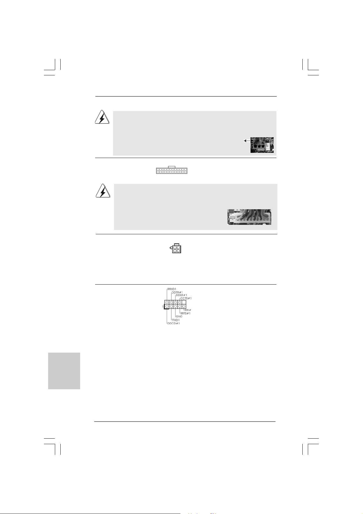
20-Pin A TX Power Supply Installation
ATX 12V Connector Please note that it is necessary
(4-pin A TX12V2) to connect a power supply with
(see p.2 No. 2) ATX 12V plug to this connector
so that it can provides sufficient
power. Failing to do so will cause
the failure to power up.
ATX Power Connector Please connect an ATX power
(24-pin ATXPW R1) supply to this connector.
(see p.2 No. 4)
Though this motherboard provides 24-pin ATX power connector, it can still work
if you adopt a traditional 20-pin ATX power supply. To use the 20-pin ATX power
supply, please plug your power supply along with Pin 1 and Pin 13.
24 13
12 1
24 13
12 1
Though this motherboard provides 4-Pin CPU fan (Quiet Fan) support, the 3-Pin
CPU fan still can work successfully even without the fan speed control function.
If you plan to connect the 3-Pin CPU fan to the CPU fan connector on this
motherboard, please connect it to Pin 1-3.
3-Pin Fan Installation
Pin 1-3 Connected
Serial port Header This COM1 header supports a
(9-pin COM1) serial port module.
(see p.2 No. 25)
2121
2121
21
ASRock G41M-VGS3 / G41M-VS3 Motherboard
Please refer to the warning on page 8 for the possible overclocking risk
before you apply Untied Overclocking Technology.
2.72.7
2.72.7
2.7
Serial ASerial A
Serial ASerial A
Serial A
TT
TT
T
A (SAA (SA
A (SAA (SA
A (SA
TT
TT
T
A) / Serial AA) / Serial A
A) / Serial AA) / Serial A
A) / Serial A
TT
TT
T
AII (SAAII (SA
AII (SAAII (SA
AII (SA
TT
TT
T
AII) Hard DisksAII) Hard Disks
AII) Hard DisksAII) Hard Disks
AII) Hard Disks
Installation Installation
Installation Installation
Installation
This motherboard adopts Intel
®
ICH7 south bridge chipset that supports Serial ATA
(SATA) / Serial ATAII (SAT AII) hard dis k s. You may install SATA / SAT AII hard disk s on
this motherboard for internal storage devices. This section will guide you to install the
SATA / SATAII hard disks.
STEP 1: Install the SATA / SATAII hard disks into the drive bays of your cha ssis.
STEP 2: Connect the SATA power cable to the SATA / SATAII hard disk.
STEP 3: Connect one end of the SATA data ca ble to the motherboard’s SAT AII
connector.
STEP 4: Connect the other end of the SATA data ca ble to the SAT A / SATAII hard
disk.
2.82.8
2.82.8
2.8
Driver Installation GuideDriver Installation Guide
Driver Installation GuideDriver Installation Guide
Driver Installation Guide
To install the drivers to your system, please insert the support CD to your optical drive
first. Then, the drivers compatible to your system can be auto-detected and listed on
the support CD driver page. Please follow the order from up to bottom side to install
those required drivers. Therefore, the drivers you install can work properly.
2.92.9
2.92.9
2.9
Untied Overclocking TUntied Overclocking T
Untied Overclocking TUntied Overclocking T
Untied Overclocking T
echnologyechnology
echnologyechnology
echnology
This motherboard supports Untied Overclocking Technology, which means during
overclocking, FSB enjoys better margin due to fixed PCI / PCIE buses. Before you
enable Untied Overclocking function, please enter “Overclock Mode” option of BIOS
setup to set the selection from [Auto] to [Manual]. Therefore, CPU FSB is untied
during overclocking, but PCI / PCIE buses are in the fixed mode so that FSB can
operate under a more stable overclocking environment.
EnglishEnglish
EnglishEnglish
English
2222
2222
22
ASRock G41M-VGS3 / G41M-VS3 Motherboard
3. BIOS Information3. BIOS Information
3. BIOS Information3. BIOS Information
3. BIOS Information
The Flash Memory on the motherboard stores BIOS Setup Utility. When you start up
the computer, please press <F2> during the Power-On-Self-Test (POST) to enter
BIOS Setup utility; otherwise, POST continues with its test routines. If you wish to
enter BIOS Setup after POST, please restart the system by pressing <Ctl> + <Alt> +
<Delete>, or pressing the reset button on the system chassis. The BIOS Setup pro-
gram is designed to be user-friendly. It is a menu-driven program, which allows you to
scroll through its various sub-menus and to select among the predetermined choices.
For the detailed information about BIOS Setup, please refer to the User Manual (PDF
file) contained in the Support CD.
4. Sof4. Sof
4. Sof4. Sof
4. Sof
tware Supportware Suppor
tware Supportware Suppor
tware Suppor
t CD informationt CD information
t CD informationt CD information
t CD information
This motherboard supports various Microsoft
®
Windows
®
operating systems: 7 / 7
64-bit / Vista
TM
/ Vista
TM
64-bit / XP / XP 64-bit. The Support CD that came with the
motherboard contains necessary drivers and useful utilities that will enhance
motherboard features. To begin using the Support CD, insert the CD into your CD-
ROM drive. It will display the Main Menu automatically if “AUTORUN” is enabled in
your computer. If the Main Menu does not appear automatically, locate and double-
click on the file “ASSETUP.EXE” from the BIN folder in the Support CD to display the
menus.
EnglishEnglish
EnglishEnglish
English
2323
2323
23
ASRock G41M-VGS3 / G41M-VS3 Motherboard
1. Einführung1. Einführung
1. Einführung1. Einführung
1. Einführung
Wir danken Ihnen für den Kauf des ASRock G41M-VGS3 / G41M-VS3 Motherboard,
ein zuverlässiges Produkt, welches unter den ständigen, strengen Qualitätskontrollen
von ASRock gefertigt wurde. Es bietet Ihnen exzellente Leistung und robustes Design,
gemäß der Verpflichtung von ASRock zu Qualität und Halbarkeit.
Diese Schnellinstallationsanleitung führt in das Motherboard und die schrittweise
Installation ein. Details über das Motherboard finden Sie in der
Bedienungsanleitung auf der Support-CD.
Da sich Motherboard-Spezifikationen und BIOS-Software verändern
können, kann der Inhalt dieses Handbuches ebenfalls jederzeit geändert
werden. Für den Fall, dass sich Änderungen an diesem Handbuch
ergeben, wird eine neue Version auf der ASRock-Website, ohne weitere
Ankündigung, verfügbar sein. Die neuesten Grafikkarten und unterstützten
CPUs sind auch auf der ASRock-Website aufgelistet.
ASRock-Website: http://www.asrock.com
Wenn Sie technische Unterstützung zu Ihrem Motherboard oder spezifische
Informationen zu Ihrem Modell benötigen, besuchen Sie bitte unsere
Webseite:
www.asrock.com/support/index.asp
1.1 Kartoninhalt
ASRock G41M-VGS3 / G41M-VS3 Motherboard
(Micro ATX-Formfaktor: 22.6 cm x 17.0 cm; 8.9 Zoll x 6.7 Zoll)
ASRock G41M-VGS3 / G41M-VS3 Schnellinstallationsanleitung
ASRock G41M-VGS3 / G41M-VS3_ Support-CD
Zwei Seriell-ATA- (SATA) Datenkabel (Option)
Ein I/O Shield
DeutschDeutsch
DeutschDeutsch
Deutsch
2424
2424
24
ASRock G41M-VGS3 / G41M-VS3 Motherboard
DeutschDeutsch
DeutschDeutsch
Deutsch
1.21.2
1.21.2
1.2
SpezifikationenSpezifikationen
SpezifikationenSpezifikationen
Spezifikationen
Plattform - Micro ATX-Formfaktor: 22.6 cm x 17.0 cm; 8.9 Zoll x 6.7 Zoll
CPU - LGA 775 für Intel
®
Core
TM
2 Extreme / Core
TM
2 Quad / Core
TM
2 Duo / Pentium
®
Dual Core / Celeron
®
Dual Core / Celeron
®
unterstützt Penryn Quad Core Yorkfield und Dual Core
Wolfdale Prozessoren
- FSB1333/1066/800/533 MHz
- Unterstützt Hyper-Threading-Technologie
(siehe VORSICHT 1)
- Unterstützt U ntied-Überta ktungstechnologie
(siehe VORSICHT 2)
- Unterstützt EM64T -CPU
Chipsatz - Northbridge: Intel
®
G41
- Southbridge: Intel
®
ICH7
Speicher - Unterstützung von Dual-Kanal-Speichertechnologie
(siehe VORSICHT 3)
- 2 x Steckplätze für DDR3
- Unterstützt DDR3 1333(OC)/1066/800 non-ECC,
ungepufferter Speicher (siehe VORSICHT 4)
- Max. Kapazität des Systemspeichers: 8GB
(siehe VORSICHT 5)
Erweiterungs- - 1 x PCI Express x16-Steckplätze
steckplätze - 1 x PCI -Steckplätze
Onboard-VGA - Intel
®
Graphics Media Accelerator X4500
- Pixel Shader 4.0, DX10 VGA
- Maximal gemeinsam genutzter Speicher 1759MB
(siehe VORSICHT 6)
- Unterstützt D-Sub mit einer maximalen Auflösung von
2048 x 1536 bei 75 Hz
Audio - 5.1 CH HD Audio (VIA
®
VT1705 Audio Codec)
LAN - G41M-VGS3
Atheros
®
PCIE x1 Gigabit LAN AR8151,
speed 10/100/1000 Mb/s
- G41M-VS3
Atheros
®
PCIE x1 LAN AR8152, speed 10/100 Mb/s
- Unterstützt Wake-On-LAN
E/A-Anschlüsse I/O Panel
an der - 1 x PS/2 Mouse Port
Rückseite - 1 x PS/2 Keyboard Port
- 1 x VGA Port
2525
2525
25
ASRock G41M-VGS3 / G41M-VS3 Motherboard
- 4 x Ready-to-Use USB 2.0 Ports
- 1 x RJ-45 LAN Port mit LED (ACT/LINK LED und SPEED LED)
- Audioanschlüsse: Line In / Line Out / Mikrofon
Anschlüsse - 4 x SATAII-Anschlüsse, unterstützt bis 3.0 Gb/s
Datenübertragungsrate (Unterstützt keine “RAID”- und “Hot-
Plug”-Funktionen) (siehe VORSICHT 7)
- 1 x ATA100 IDE-Anschlüsse (Unterstützt bis 2 IDE-Geräte)
- 1 x Druckerport-Anschlussleiste
- 1 x COM-Anschluss-Header
- CPU/Gehäuse-Lüfteranschluss
- 24-pin ATX-Netz-Header
- 4-pin anschluss für 12V-ATX-Netzteil
- Anschluss für Audio auf der Gehäusevorderseite
- 2 x USB 2.0 Buchse (unterstützt 4 USB 2.0 Ports)
(siehe VORSICHT 8)
BIOS - 8Mb AMI BIOS
- AMI legal BIOS mit U nterstützung für “Plug and Play”
- ACPI 1.1-Weckfunktionen
- SMBIOS 2.3.1
- VCCM, NB, VTT, GTLRef Stromspannung Multianpassung
Support-CD - Treiber, Dienstprogramme, Antivirussoftware
(Probeversion), ASRock-Software-Suite (CyberLink
DVD Suite und Creative Sound Blaster X-Fi MB) (OEM- und
Testversion)
Einzigartige - ASRock OC Tuner (siehe VORSICHT 9)
Eigenschaft - Intelligent Energy Saver (Intelligente Energiesparfunktion)
(siehe VORSICHT 10)
- Sofortstart
- ASRock Instant Flash (siehe VORSICHT 11)
- ASRock OC DNA (siehe VORSICHT 12)
- ASRock AIWI (siehe VORSICHT 13)
- ASRock APP Charger (siehe VORSICHT 14)
- SmartView (siehe VORSICHT 15)
- ASRock XFast USB (siehe VORSICHT 16)
- Hybrid Booster:
- Schrittloser CPU-Frequenz-Kontrolle
(siehe VORSICHT 17)
- ASRock U-COP (siehe VORSICHT 18)
- Boot Failure Guard (B.F.G. – Systemstartfehlerschutz)
Hardware Monitor - Überwachung der CPU-Temperatur
- Motherboardtemperaturerkennung
- Drehzahlmessung für CPU-Lüfter
DeutschDeutsch
DeutschDeutsch
Deutsch
2626
2626
26
ASRock G41M-VGS3 / G41M-VS3 Motherboard
DeutschDeutsch
DeutschDeutsch
Deutsch
WARNUNG
Beachten Sie bitte, dass Overclocking, einschließlich der Einstellung im BIOS, Anwenden
der Untied Overclocking-Technologie oder Verwenden von Overclocking-Werkzeugen von
Dritten, mit einem gewissen Risiko behaftet ist. Overclocking kann sich nachteilig auf die
Stabilität Ihres Systems auswirken oder sogar Komponenten und Geräte Ihres Systems
beschädigen. Es geschieht dann auf eigene Gefahr und auf Ihre Kosten. Wir übernehmen
keine Verantwortung für mögliche Schäden, die aufgrund von Overclocking verursacht
wurden.
VORSICHT!
1. Die Einstellung der “Hyper-Threading Technology”, finden Sie auf Seite
34 des auf der Support-CD enthaltenen Benutzerhandbuches
beschrieben.
2. Dieses Motherboard unterstützt die Untied-Übertaktungstechnologie.
Unter “Entkoppelte Übertaktungstechnologie” auf Seite 21 finden Sie
detaillierte Informationen.
3. Dieses Motherboard unterstützt Dual-Kanal-Speichertechnologie. Vor
Implementierung der Dual-Kanal-Speichertechnologie müssen Sie
die Installationsanleitung für die Speichermodule auf Seite 14 zwecks
richtiger Installation gelesen haben.
4. Die unterstützten Arbeitsspeicherfrequenzen und die entsprechende
CPU FSB-Frequenz entnehmen Sie bitte der nachstehenden Tabelle.
CPU FSB-Frequenz Unterstützte Arbeitsspeicherfrequenz
1333 DDR3 800, DDR3 1066, DDR3 1333
1066 DDR3 800, DDR3 1066
800 DDR3 800
533 DDR3 800
* DDR3 1333 peichermodule werden in Übertakten Modus funktionieren.
* Bei Verwendung einer FSB533-CPU auf diesem Motherboard lauft
esmit DDR3 533, wenn Sie ein DDR3 800-Speichermodul verwenden.
* Wenn Sie einen FSB1333-CPU und DDR3 1333 Speichermodul
adoptieren auf dieser Hauptplatine adoptieren, müssen Sie die
Steckbrücke regulieren. Bitte beziehen Sie sich auf Seite 31 für
korrekte Steckbrücke Einstellungen.
- Drehzahlmessung für Gehäuselüfter
- CPU-Lüftergeräuschdämpfung
- Spannungsüberwachung: +12V, +5V, +3.3V, Vcore
Betriebssysteme - Unterstützt Microsoft
®
Windows
®
7 / 7 64-Bit / Vista
TM
/
Vista
TM
64-Bit / XP / XP 64-Bit
Zertifizierungen - FCC, CE, WHQL
- Gemäß Ökodesign-Richtlinie (ErP/EuP) (Stromversorgung
gemäß Ökodesign-Richtlinie (ErP/EuP) erforderlich)
(siehe VORSICHT 19)
* Für die ausführliche Produktinformation, besuchen Sie bitte unsere Website:
http://www.asrock.com
2727
2727
27
ASRock G41M-VGS3 / G41M-VS3 Motherboard
5. Durch Betriebssystem-Einschränkungen kann die tatsächliche
Speichergröße weniger als 4 GB betragen, da unter Windows
®
7 / Vista™
/ XP etwas Speicher zur Nutzung durch das System reserviert wird. Unter
Windows
®
OS mit 64-Bit-CPU besteht diese Einschränkung nicht.
6. Die Maximalspeichergröße ist von den Chipshändler definiert und
umgetauscht. Bitte überprüfen Sie Intel
®
website für die neuliche
Information.
7. Vor Installation der SATAII-Festplatte an den SATAII-Anschluss lesen Sie
bitte “Setup-Anleitung für SATAII-Festplatte” auf Seite 24 der
“Bedienungsanleitung” auf der Support-CD, um Ihre SATAII-Festplatte
dem SATAII-Modus anzugleichen. Sie können die SATA-Festplatte auch
direkt mit dem SATAII-Anschluss verbinden.
8. Das Power Management für USB 2.0 arbeitet unter Microsoft
®
Windows
®
7 64-Bit / 7 / Vista
TM
64-Bit / Vista
TM
/ XP 64-Bit / XP SP1 oder SP2
einwandfrei.
9. Es ist ein benutzerfreundlicher ASRock Übertaktenswerkzeug, das
erlaubt, dass Sie Ihr System durch den Hardware-Monitor Funktion zu
überblicken und Ihre Hardware-Geräte übertakten, um die beste
Systemleistung unter der Windows
®
Umgebung zu erreichen. Besuchen
Sie bitte unsere Website für die Operationsverfahren von ASRock OC
Tuner. ASRock-Website: http://www.asrock.com
10. Mit einem fortschrittlichen, eigenständigen Hard- und Softwaredesign
nutzt der Intelligent Energy Saver eine revolutionäre Technologie, die
bisher unerreichte Energieeinsparungen ermöglicht. Mit anderen Worten:
Sie verbrauchen besonders wenig Energie und erreichen einen hohen
Wirkungsgrad, ohne dass dies zu Lasten der Rechenleistung geht. Auf
unseren Internetseiten finden Sie einige Erläuterungen zur
Funktionsweise des Intelligent Energy Saver.
ASRock-Website: http://www.asrock.com
11. ASRock Instant Flash ist ein im Flash-ROM eingebettetes BIOS-Flash-
Programm. Mithilfe dieses praktischen BIOS-Aktualisierungswerkzeugs
können Sie das System-BIOS aktualisieren, ohne dafür zuerst
Betriebssysteme wie MS-DOS oder Windows
®
aufrufen zu müssen. Mit
diesem Programm bekommen Sie durch Drücken der <F6>-Taste
während des POST-Vorgangs oder durch Drücken der <F2>-Taste im
BIOS-Setup-Menü Zugang zu ASRock Instant Flash. Sie brauchen dieses
Werkzeug einfach nur zu starten und die neue BIOS-Datei auf Ihrem
USB-Flash-Laufwerk, Diskettenlaufwerk oder der Festplatte zu
speichern, und schon können Sie Ihr BIOS mit nur wenigen
Klickvorgängen ohne Bereitstellung einer zusätzlichen Diskette oder
eines anderen komplizierten Flash-Programms aktualisieren. Achten Sie
darauf, dass das USB-Flash-Laufwerk oder die Festplatte das
Dateisystem FAT32/16/12 benutzen muss.
DeutschDeutsch
DeutschDeutsch
Deutsch
2828
2828
28
ASRock G41M-VGS3 / G41M-VS3 Motherboard
DeutschDeutsch
DeutschDeutsch
Deutsch
12. Allein der Name – OC DNA* – beschreibt es wörtlich, was die Software
zu leisten vermag. OC DNA ist ein von ASRock exklusiv entwickeltes
Dienstprogramm, das Nutzern eine bequeme Möglichkeit bietet,
Übertaktungseinstellungen aufzuzeichnen und sie Anderen mitzuteilen.
Es hilft Ihnen, Ihre Übertaktungsaufzeichnung im Betriebssystem zu
speichern und vereinfacht den komplizierten Aufzeichnungsvorgang von
Übertaktungseinstellungen. Mit OC DNA können Sie Ihre
Übertaktungseinstellungen als Profil abspeichern und Ihren Freunden
zugänglich machen! Ihre Freunde können dann das Übertaktungsprofil
auf ihren eigenen Systemen laden, um dieselben
Übertaktungseinstellungen. Mit OC DNA können Sie Ihre
Übertaktungseinstellungen als Profil abspeichern und Ihren Freunden
zugänglich machen! Ihre Freunde können dann das Übertaktungsprofil
auf ihren eigenen Systemen laden, um dieselben
Übertaktungseinstellungen wie Sie zu erhalten! Beachten Sie bitte, dass
das Übertaktungsprofil nur bei einem identischen Motherboard
gemeinsam genutzt und funktionsfähig gemacht werden kann.
Übertaktungseinstellungen wie Sie zu erhalten! Beachten Sie bitte, dass
das Übertaktungsprofil nur bei einem identischen Motherboard
gemeinsam genutzt und funktionsfähig gemacht werden kann.
13. Das Erlebnis intuitiver, bewegungsgesteuerter Spiele ist nicht mehr nur
noch an der Wii möglich. Das ASRock AIWI-Dienstprogramm führt eine
neue Möglichkeit der PC-Spielsteuerung ein. ASRock AIWI ist das
weltweit erste Dienstprogramm, mit dem Sie Ihr iPhone/iPod touch in
einen Joystick zur Steuerung Ihrer PC-Spiele verwandeln können. Sie
müssen lediglich das ASRock AIWI-Dienstprogramm – entweder von der
offiziellen ASRock-Webseite oder der ASRock-Software-CD Ihres
Motherboards – installieren sowie das kostenlose AIWI Lite vom App
Store auf Ihr iPhone/iPod touch herunterladen. Verbinden Sie Ihren PC
und das Apple-Gerät via Bluetooth oder Wi-Fi-Netzwerk – schon können
Sie die bewegungsgesteuerten Spiele genießen. Bitte denken Sie
außerdem daran, regelmäßig einen Blick auf die offizielle ASRock-
Webseite zu werfen; wir bieten stets topaktuelle Informationen über die
unterstützten Spiele!
ASRock-Webseite: http://www.asrock.com/Feature/Aiwi/index.asp
14. Wenn Sie nach einer schnelleren, weniger eingeschränkten Möglichkeit
zur Aufladung Ihrer Apple-Geräte (z. B. iPhone/iPad/iPod touch) suchen,
bietet ASRock Ihnen eine wunderbare Lösung – den ASRock APP
Charger. Installieren Sie einfach den ASRock APP Charger-Treiber;
dadurch lädt sich Ihr iPhone wesentlich schneller über einen Computer
auf – genaugenommen bis zu 40 % schneller als zuvor. Der ASRock
APP Charger ermöglicht Ihnen die schnelle Aufladung mehrerer Apple-
Geräte gleichzeitig; der Ladevorgang wird sogar dann fortgesetzt, wenn
der PC den Ruhezustand (S1), Suspend to RAM-Modus (S3) oder
Tiefschlafmodus (S4) aufruft oder ausgeschaltet wird (S5). Nach der
Installation des APP Charger-Treibers können Sie im Handumdrehen das
großartigste Ladeerlebnis überhaupt genießen. ASRock-Webseite: http://
www.asrock.com/Feature/AppCharger/index.asp
2929
2929
29
ASRock G41M-VGS3 / G41M-VS3 Motherboard
Gebrückt Offen
1.3 Einstellung der Jumper1.3 Einstellung der Jumper
1.3 Einstellung der Jumper1.3 Einstellung der Jumper
1.3 Einstellung der Jumper
Die Abbildung verdeutlicht, wie Jumper
gesetzt werden. Werden Pins durch
Jumperkappen verdeckt, ist der Jumper
“Gebrückt”. Werden keine Pins durch
Jumperkappen verdeckt, ist der Jumper
“Offen”. Die Abbildung zeigt einen 3-Pin
Jumper dessen Pin1 und Pin2 “Gebrückt”
sind, bzw. es befindet sich eine Jumper-
Kappe auf diesen beiden Pins.
DeutschDeutsch
DeutschDeutsch
Deutsch
15. SmartView, eine neue Internetbrowserfunktion, ist eine intelligente IE-
Startseite, die meist besuchte Internetseiten, Ihren Browserverlauf,
Facebook-Freunde und Nachrichten in Echtzeit miteinander kombiniert:
In einer speziellen Ansicht, die das Internet noch angenehmer und aufre-
gender macht. ASRock-Motherboards werden exklusiv mit der Smart-
View-Software geliefert, die auch dafur sorgt, dass Sie immer mit Ihren
Freunden in Verbindung bleiben. Die SmartView-Funktionen konnen Sie
mit den Windows
®
-Betriebssystemen 7 / 7, 64 Bit / Vista
TM
/ Vista
TM
64
Bit und dem Internet Explorer ab Version 8 nutzen. ASRock-W ebsite:
http://www.asrock.com/Feature/SmartView/index.asp
16. ASRocks XFast USB dient der Steigerung der Leistungsfähigkeit Ihrer
USB-Speichergeräte. Die Leistung kann je nach Eigenschaften des
Gerätes variieren.
17. Obwohl dieses Motherboard stufenlose Steuerung bietet, wird
Overclocking nicht empfohlen. Frequenzen, die von den empfohlenen
CPU-Busfrequenzen abweichen, können Instabilität des Systems
verursachen oder die CPU beschädigen.
18. Wird eine Überhitzung der CPU registriert, führt das System einen
automatischen Shutdown durch. Bevor Sie das System neu starten, prüfen
Sie bitte, ob der CPU-Lüfter am Motherboard richtig funktioniert, und
stecken Sie bitte den Stromkabelstecker aus und dann wieder ein. Um die
Wärmeableitung zu verbessern, bitte nicht vergessen, etwas
Wärmeleitpaste zwischen CPU und Kühlkörper zu sprühen.
19. EuP steht für Energy Using Product und kennzeichnet die Ökodesign-
Richtlinie, die von der Europäischen Gemeinschaft zur Festlegung des
Energieverbrauchs von vollständigen Systemen in Kraft gesetzt wurde.
Gemäß dieser Ökodesign-Richtlinie (EuP) muss der gesamte
Netzstromverbrauch von vollständigen Systemen unter 1,00 Watt liegen,
wenn sie ausgeschaltet sind. Um dem EuP-Standard zu entsprechen, sind
ein EuP-fähiges Motherboard und eine EuP-fähige Stromversorgung
erforderlich. Gemäß einer Empfehlung von Intel muss eine EuP-fähige
Stromversorgung dem Standard entsprechen, was bedeutet, dass bei einem
Stromverbrauch von 100 mA die 5-Volt-Standby-Energieeffizienz höher als
50% sein sollte. Für die Wahl einer EuP-fähigen Stromversorgung
empfehlen wir Ihnen, weitere Details beim Hersteller der Stromversorgung
abzufragen.
3030
3030
30
ASRock G41M-VGS3 / G41M-VS3 Motherboard
2-Pin jumper
Standard (EuP aktivieren)
EUP LAN / EUP-Audio-Jumper
(EUP_LAN1, 3-pol. Jumper, siehe Seite 2, Nr. 23)
(EUP_AUDIO1, 3-pol. Jumper, siehe Seite 2, Nr. 22)
Hinweis: Das Jumper-Design EUP_LAN und EUP_AUDIO verringert den
Energieverbrauch dieses Motherboards, um dem Standard der
Ökodesign-Richtlinie (EuP) zu entsprechen. Mit einem ASRock-
Motherboard gemäß der Ökodesign-Richtlinie (EuP) und einer
Stromversorgung, deren 5 VSB-Energieeffizienz der Standby-Spannung
bei einer Stromaufnahme von 100 mA höher ist als 50%, ist Ihr System
befähigt, sich dem Standard der Ökodesign-Richtlinie (EuP)
auszusetzen. Die Standardeinstellung ist EuP-aktiviert (Pin 1 und Pin 2
sind geschlossen). Möchten Sie diese Energiesparfunktion deaktivieren,
müssen Sie Pin 2 und Pin 3 schließen. Wird der EUP_LAN-Jumper auf
aktiviert gesetzt, beachten Sie bitte, dass die Wake-On-LAN-Funktion bei
S3 (Suspend-to-RAM), S4 (Suspend-to-Disk) und S5 (Standby)
deaktiviert ist.
Jumper Einstellun Beschreibung
PS2_USB_PWR1 Überbrücken Sie Pin2, Pin3, um
(siehe S.2 - No. 1) +5VSB (Standby) zu setzen
und die PS/2 oder USB-
Weckfunktionen zu aktivieren.
Hinweis: Um +5VSB nutzen zu können, muss das Netzteil auf dieser Leitung 2A
oder mehr leisten können.
CMOS löschen
(CLRCMOS1, 2-Pin jumper)
(siehe S.2 - No. 18)
Hinweis: Mit CLRCMOS1 können Sie die Daten im CMOS löschen. Die CMOS Daten
beinhalten die Systeminformationen wie Systemkennwort, Datum, Zeit
und System-Setupeinstellungen. Um die Einstellungen zu löschen und
Default-Werte wiederherzustellen, schalten Sie den Computer aus,
ziehen Sie den Netzstecker und überbrücken Sie 2-pin von CLRCMOS1
mithilfe des Jumpers für 5 Sekunden.
(EuP deaktivieren)
DeutschDeutsch
DeutschDeutsch
Deutsch
 Loading...