


E350M1/USB3
1
ASRock E350M1/USB3 Motherboard
English
Copyright Notice:
No part of this installation guide may be reproduced, transcribed, transmitted, or translated in any language, in any form or by any means, except duplication of documentation
by the purchaser for backup purpose, without written consent of ASRock Inc.
Products and corporate names appearing in this guide may or may not be registered
trademarks or copyrights of their respective companies, and are used only for identifi ca-
tion or explanation and to the owners’ benefi t, without intent to infringe.
Disclaimer:
Specifi cations and information contained in this guide are furnished for informational use
only and subject to change without notice, and should not be constructed as a commitment by ASRock. ASRock assumes no responsibility for any errors or omissions that may
appear in this guide.
With respect to the contents of this guide, ASRock does not provide warranty of any kind,
either expressed or implied, including but not limited to the implied warranties or conditions of merchantability or fi tness for a particular purpose. In no event shall ASRock, its
directors, offi cers, employees, or agents be liable for any indirect, special, incidental, or
consequential damages (including damages for loss of profi ts, loss of business, loss of
data, interruption of business and the like), even if ASRock has been advised of the possibility of such damages arising from any defect or error in the guide or product.
This device complies with Part 15 of the FCC Rules. Operation is subject to the following
two conditions:
(1) this device may not cause harmful interference, and
(2) this device must accept any interference received, including interference that
may cause undesired operation.
CALIFORNIA, USA ONLY
The Lithium battery adopted on this motherboard contains Perchlorate, a toxic substance
controlled in Perchlorate Best Management Practices (BMP) regulations passed by the
California Legislature. When you discard the Lithium battery in California, USA, please
follow the related regulations in advance.
“Perchlorate Material-special handling may apply, see
www.dtsc.ca.gov/hazardouswaste/perchlorate”
ASRock Website: http://www.asrock.com
Published June 2011
Copyright©2011 ASRock INC. All rights reserved.

2
ASRock E350M1/USB3 Motherboard
Motherboard Layout
English
1 CPU Fan Connector (CPU_FAN1) 13 Chassis Speaker Header
2 Chassis Fan Connector (CHA_FAN1) (SPEAKER 1, White)
3 CPU Fan 14 Chassis Fan Connector (CHA_FAN2)
4 CPU Heatsink 15 32Mb SPI Flash
5 2 x 240-pin DDR3 DIMM Slots 16 PCI Express 2.0 x16 Slot (PCIE1, Blue)
(DDR3_A1, DDR3_A2, Blue) 17 Consumer Infrared Module Header (CIR1)
6 Clear CMOS Jumper (CLRCMOS1) 18 USB 2.0 Header (USB8_9, Blue)
7 ATX Power Connector (ATXPWR1) 19 USB 2.0 Header (USB6_7, Blue)
8 System Panel Header (PANEL1, White) 20 Front Panel Audio Header
9 SATA3 Connector (SATA3_4, White) (HD_AUDIO1, White)
10 SATA3 Connector (SATA3_2, White) 21 COM Port Header (COM1)
11 SATA3 Connector (SATA3_3, White) 22 AMD A50M Chipset
12 SATA3 Connector (SATA3_1, White)
SPEAKER1
1
PANEL1
HDLED RESET
PLED PWRBTN
1
CMOS
Battery
32Mb
BIOS
17.0cm (6.7in)
17.0cm (6.7in)
Super
IO
FSB800
DDR3_A1 (64bit, 240-pin module)
FSB800
DDR3_A2 (64bit, 240-pin module)
1
USB6_7
PCIE1
1
USB8_9
CHA_FAN2
SATA3_1
SATA3_2
SATA3_3
SATA3_4
HD_AUDIO1
1
AUDIO
CODEC
LAN
PHY
1
COM1
CHA_FAN1
RoHS
SATA3 6Gb/s
USB3.0
T: US B0
B:USB1
PS2
Keyboard/Mouse
VGA1
DVI_CON1
HDMI1
USB2.0
T: US B2
B:USB3
eSATA3_1
USB 2.0
T: U SB 4
B: USB5
Top:
RJ-45
Top:
CTR BASS
Center:
REAR SPK
Bottom:
Optical
SPDIF
Top:
LINE IN
Center:
FRONT
Bottom:
MIC IN
CLRCMOS1
1
E350M1/USB3
DX11
CPU_FAN1
1
2
4
3
5
7
6
8
9
10
11
12
13
14
15
16
17
18
19
20
21
DDR3
CIR1
1
22
3
ASRock E350M1/USB3 Motherboard
English
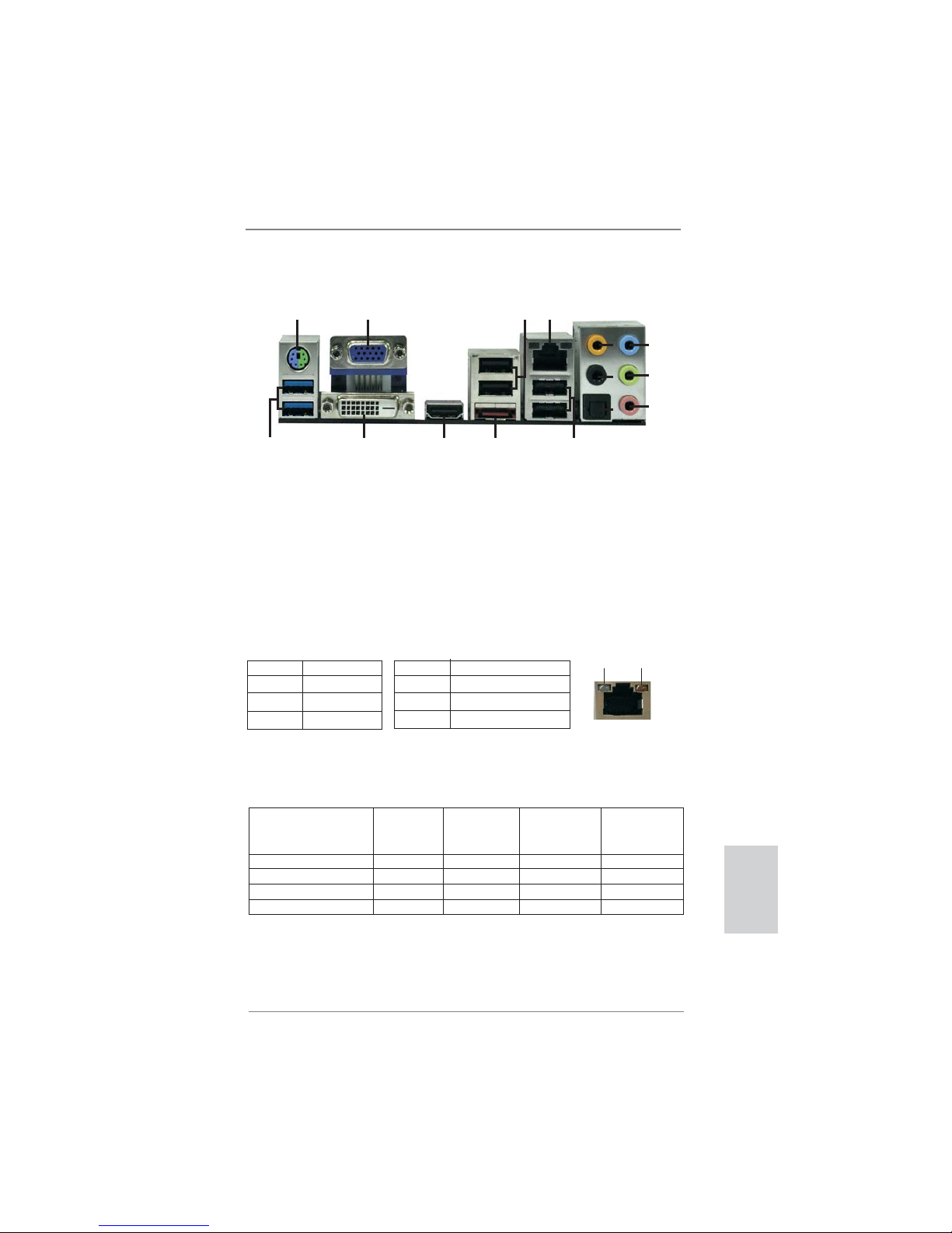
I/O Panel
**
If you use 2-channel speaker, please connect the speaker’s plug into “Front Speaker Jack”.
See the table below for connection details in accordance with the type of speaker you use.
TABLE for Audio Output Connection
Audio Output Channels Front Speaker Rear Speaker Central / Bass Line In or
(No. 9) (No. 6) (No. 5) Side Speaker
(No. 8)
2 V -- -- -4 V V -- -6 V V V -8 V V V V
* There are two LED next to the LAN port. Please refer to the table below for the LAN port LED
indications.
LAN Port LED Indications
Activity/Link LED SPEED LED
Status Description Status Description
Off No Link Off 10Mbps connection
Blinking Data Activity Orange 100Mbps connection
On Link Green 1Gbps connection
ACT/LINK
LED
SPEED
LED
LAN Port
1 PS/2 Keyboard/Mouse Port (Purple/Green) ** 9 Front Speaker (Lime)
2 VGA/D-Sub Port 10 Microphone (Pink)
3 USB 2.0 Ports (USB23) 11 USB 2.0 Ports (USB45)
* 4 LAN RJ-45 Port 12 eSATA3 Port
5 Central / Bass (Orange) 13 VGA/HDMI Port
6 Rear Speaker (Black) 14 VGA/DVI-D Port
7 Optical SPDIF Out Port 15 USB 3.0 Ports (USB01)
8 Line In (Light Blue)
1
2
5
3
6
7
8
9
10
13
14
12
4
15
11

4
ASRock E350M1/USB3 Motherboard
To enable Multi-Streaming function, you need to connect a front panel audio cable to the front
panel audio header. After restarting your computer, you will fi nd “Mixer” tool on your system.
Please select “Mixer ToolBox” , click “Enable playback multi-streaming”, and click
“ok”. Choose “2CH”, “4CH”, “6CH”, or “8CH” and then you are allowed to select “Realtek HDA
Primary output” to use Rear Speaker, Central/Bass, and Front Speaker, or select “Realtek
HDA Audio 2nd output” to use front panel audio.
English

5
ASRock E350M1/USB3 Motherboard
1. Introduction
Thank you for purchasing ASRock E350M1/USB3 motherboard, a reliable motherboard produced under ASRock’s consistently stringent quality control. It delivers
excellent performance with robust design conforming to ASRock’s commitment to
quality and endurance.
This Quick Installation Guide contains introduction of the motherboard and step-bystep installation guide. More detailed information of the motherboard can be found
in the user manual presented in the Support CD.
Because the motherboard specifi cations and the BIOS software might be
updated, the content of this manual will be subject to change without notice. In case any modifi cations of this manual occur, the updated version
will be available on ASRock website without further notice. You may fi nd
the latest VGA cards and CPU support lists on ASRock website as well.
ASRock website http://www.asrock.com
If you require technical support related to this motherboard, please visit
our website for specifi c information about the model you are using.
www.asrock.com/support/index.asp
1.1 Package Contents
ASRock E350M1/USB3 Motherboard
(Mini-ITX Form Factor: 6.7-in x 6.7-in, 17.0 cm x 17.0 cm)
ASRock E350M1/USB3 Quick Installation Guide
ASRock E350M1/USB3 Support CD
2 x Serial ATA (SATA) Data Cables (Optional)
1 x I/O Panel Shield
ASRock Reminds You...
To get better performance in Windows® 7 / 7 64-bit / Vista
TM
/ VistaTM 64bit, it is recommended to set the BIOS option in Storage Confi guration to
AHCI mode. For the BIOS setup, please refer to the “User Manual” in our
support CD for details.
English
6
ASRock E350M1/USB3 Motherboard
English
1.2 Specifications
Platform - Mini-ITX Form Factor: 6.7-in x 6.7-in, 17.0 cm x 17.0 cm
- All Solid Capacitor design (100% Japan-made high-quality
Conductive Polymer Capacitors)
CPU - AMD Dual-Core Zacate E350/E350D APU
- Supports AMD’s Cool ‘n’ Quiet
TM
Technology
- UMI 2.5 GT/s
Chipset - AMD A50M Chipset
Memory - 2 x DDR3 DIMM slots
- Supports DDR3 1066/800 non-ECC, un-buffered
memory
- Max. capacity of system memory: 16GB (see CAUTION 1)
Expansion Slot - 1 x PCI Express 2.0 x16 slot (blue @ x4 mode)
Graphics - Integrated AMD Radeon HD 6310 graphics
- DX11 class iGPU, Pixel Shader 5.0
- Max. shared memory 512MB (see CAUTION 2)
- Three VGA Output options: D-Sub, DVI-D and HDMI
- Supports HDMI Technology with max. resolution up to
1920x1200 (1080P)
- Supports DVI with max. resolution up to 1920x1200 @ 75Hz
- Supports D-Sub with max. resolution up to 2048x1536 @
85Hz
- Supports HDCP function with DVI and HDMI ports
- Supports Full HD 1080p Blu-ray (BD) / HD-DVD playback
with DVI and HDMI ports
- Supports Dolby
®
TrueHD and DTS-HD Master Audio
through HDMI port
Audio - 7.1 CH HD Audio with Content Protection
(Realtek ALC892 Audio Codec)
- Premium Blu-ray audio support
LAN - PCIE x1 Gigabit LAN 10/100/1000 Mb/s
- Realtek RTL8111E
- Supports Wake-On-LAN
- Supports LAN Cable Detection
- Supports Energy Effi cient Ethernet 802.3az
Rear Panel I/O I/O Panel
- 1 x PS/2 Keyboard/Mouse Port
- 1 x VGA/D-Sub Port
- 1 x VGA/DVI-D Port
- 1 x HDMI Port
7
ASRock E350M1/USB3 Motherboard
English
- 1 x Optical SPDIF Out Port
- 4 x Ready-to-Use USB 2.0 Ports
- 1 x eSATA3 Connector
- 2 x Ready-to-Use USB 3.0 Ports
- 1 x RJ-45 LAN Port with LED (ACT/LINK LED and SPEED
LED)
- HD Audio Jack: Rear Speaker/Central/Bass/Line in/Front
Speaker/Microphone (see CAUTION 3)
SATA 3 - 4 x SATA3 6.0 Gb/s connectors, support NCQ, AHCI and
"Hot Plug" functions
USB 3.0 - 2 x USB 3.0 ports by Etron EJ168A, support USB
1.0/2.0/3.0 up to 5Gb/s
Connector - 4 x SATA3 6.0Gb/s connectors
- 1 x CIR header
- 1 x COM port header
- CPU/Chassis FAN connector
- 24 pin ATX power connector
- Front panel audio connector
- 2 x USB 2.0 headers (support 4 USB 2.0 ports)
BIOS Feature - 32Mb AMI BIOS
- AMI UEFI Legal BIOS with GUI support
- Supports “Plug and Play”
- ACPI 1.1 Compliance Wake Up Events
- Supports jumperfree
- SMBIOS 2.3.1 Support
- DRAM, FCH, +1V, +1.8V Voltage Multi-adjustment
Support CD - Drivers, Utilities, AntiVirus Software (Trial Version), ASRock
Software Suite (CyberLink DVD Suite - OEM and Trial;
Creative Sound Blaster X-Fi MB - Trial)
Unique Feature - Instant Boot
- ASRock Instant Flash (see CAUTION 4)
- ASRock AIWI (see CAUTION 5)
- ASRock APP Charger (see CAUTION 6)
- SmartView (see CAUTION 7)
- ASRock XFast USB (see CAUTION 8)
- Hybrid Booster:
- ASRock U-COP (see CAUTION 9)
- Boot Failure Guard (B.F.G.)
Hardware - CPU Temperature Sensing
Monitor - Chassis Temperature Sensing
- CPU/Chassis Fan Tachometer
- CPU/Chassis Quiet Fan (Allow Chassis Fan Speed
Auto-Adjust by CPU or MB Temperature)

8
ASRock E350M1/USB3 Motherboard
English
CAUTION!
1. Due to the operating system limitation, the actual memory size may be
less than 4GB for the reservation for system usage under Windows® 7 /
VistaTM / XP. For Windows® OS with 64-bit CPU, there is no such limitation.
2. The maximum shared memory size is defi ned by the chipset vendor and
is subject to change. Please check AMD website for the latest information.
3. For microphone input, this motherboard supports both stereo and mono
modes. For audio output, this motherboard supports 2-channel, 4-channel, 6-channel, and 8-channel modes. Please check the table on page 3
for proper connection.
4. ASRock Instant Flash is a BIOS fl ash utility embedded in Flash ROM.
This convenient BIOS update tool allows you to update system BIOS
without entering operating systems fi rst like MS-DOS or Windows
®
. With
this utility, you can press <F6> key during the POST or press <F2> key to
BIOS setup menu to access ASRock Instant Flash. Just launch this tool
and save the new BIOS fi le to your USB fl ash drive, fl oppy disk or hard
drive, then you can update your BIOS only in a few clicks without prepar-
ing an additional fl oppy diskette or other complicated fl ash utility. Please
be noted that the USB fl ash drive or hard drive must use FAT32/16/12 fi le
system.
5. To experience intuitive motion controlled games is no longer only available at Wii. ASRock AIWI utility introduces a new way of PC gaming
operation. ASRock AIWI is the world’s fi rst utility to turn your iPhone/iPod
touch as a game joystick to control your PC games. All you have to do is
just to install the ASRock AIWI utility either from ASRock offi cial website
WARNING
Please realize that there is a certain risk involved with overclocking, including
adjusting the setting in the BIOS, applying Untied Overclocking Technology, or
using the third-party overclocking tools. Overclocking may affect your system
stability, or even cause damage to the components and devices of your system.
It should be done at your own risk and expense. We are not responsible for possible
damage caused by overclocking.
- CPU/Chassis Fan Multi-Speed Control
- Voltage Monitoring: +12V, +5V, +3.3V, CPU Vcore
OS - Microsoft® Windows® 7 / 7 64-bit / Vista
TM
/ VistaTM 64-bit
/ XP / XP Media Center / XP 64-bit compliant
Certifi cations - FCC, CE, WHQL
- ErP/EuP Ready (ErP/EuP ready power supply is required)
(see CAUTION 10)
* For detailed product information, please visit our website: http://www.asrock.com

9
ASRock E350M1/USB3 Motherboard
English
or ASRock software support CD to your motherboard, and also download
the free AIWI Lite from App store to your iPhone/iPod touch. Connecting
your PC and apple devices via Bluetooth or WiFi networks, then you can
start experiencing the exciting motion controlled games. Also, please do
not forget to pay attention to ASRock offi cial website regularly, we will
continuously provide you the most up-do-date supported games!
ASRock website: http://www.asrock.com/Feature/Aiwi/index.asp
6. If you desire a faster, less restricted way of charging your Apple devices,
such as iPhone/iPod/iPad Touch, ASRock has prepared a wonderful
solution for you - ASRock APP Charger. Simply installing the APP Char-
ger driver, it makes your iPhone charged much quickly from your com-
puter and up to 40% faster than before. ASRock APP Charger allows you
to quickly charge many Apple devices simultaneously and even supports
continuous charging when your PC enters into Standby mode (S1), Sus-
pend to RAM (S3), hibernation mode (S4) or power off (S5). With APP
Charger driver installed, you can easily enjoy the marvelous charging
experience than ever.
ASRock website: http://www.asrock.com/Feature/AppCharger/index.asp
7.
SmartView, a new function of internet browser, is the smart start page for
IE that combines your most visited web sites, your history, your Facebook
friends and your real-time newsfeed into an enhanced view for a more
personal Internet experience. ASRock motherboards are exclusively
equipped with the SmartView utility that helps you keep in touch with
friends on-the-go. To use SmartView feature, please make sure your
OS version is Windows
®
7 / 7 64 bit / VistaTM / VistaTM 64 bit, and your
browser version is IE8. ASRock website: http://www.asrock.com/Feature/
SmartView/index.asp
8. While CPU overheat is detected, the system will automatically shutdown.
Before you resume the system, please check if the CPU fan on the
motherboard functions properly and unplug the power cord, then plug it
back again. To improve heat dissipation, remember to spray thermal
grease between the CPU and the heatsink when you install the PC sys-
tem.
9. ASRock XFast USB can boost USB storage device performance. The
performance may depend on the property of the device.
10. EuP, stands for Energy Using Product, was a provision regulated by European Union to defi ne the power consumption for the completed system.
According to EuP, the total AC power of the completed system shall be
under 1.00W in off mode condition. To meet EuP standard, an EuP ready
motherboard and an EuP ready power supply are required. According to
Intel’s suggestion, the EuP ready power supply must meet the standard
of 5v standby power effi ciency is higher than 50% under 100 mA current
consumption. For EuP ready power supply selection, we recommend you
checking with the power supply manufacturer for more details.
10
ASRock E350M1/USB3 Motherboard
English
2. Installation
This is a Mini-ITX form factor (6.7" x 6.7", 17.0 x 17.0 cm) motherboard. Before you
install the motherboard, study the confi guration of your chassis to ensure that the
motherboard fi ts into it.
Make sure to unplug the power cord before installing or removing the
motherboard. Failure to do so may cause physical injuries to you and
damages to motherboard components.
2.1 Screw Holes
Place screws into the holes indicated by circles to secure the motherboard to the
chassis.
Do not over-tighten the screws! Doing so may damage the motherboard.
2.2 Pre-installation Precautions
Take note of the following precautions before you install motherboard components
or change any motherboard settings.
1. Unplug the power cord from the wall socket before touching any component.
2. To avoid damaging the motherboard components due to static electricity,
NEVER place your motherboard directly on the carpet or the like. Also
remember to use a grounded wrist strap or touch a safety grounded object
before you handle components.
3. Hold components by the edges and do not touch the ICs.
4. Whenever you uninstall any component, place it on a grounded antistatic pad or
in the bag that comes with the component.
Before you install or remove any component, ensure that the power is
switched off or the power cord is detached from the power supply.
Failure to do so may cause severe damage to the motherboard, peripherals,
and/or components.
11
ASRock E350M1/USB3 Motherboard
English
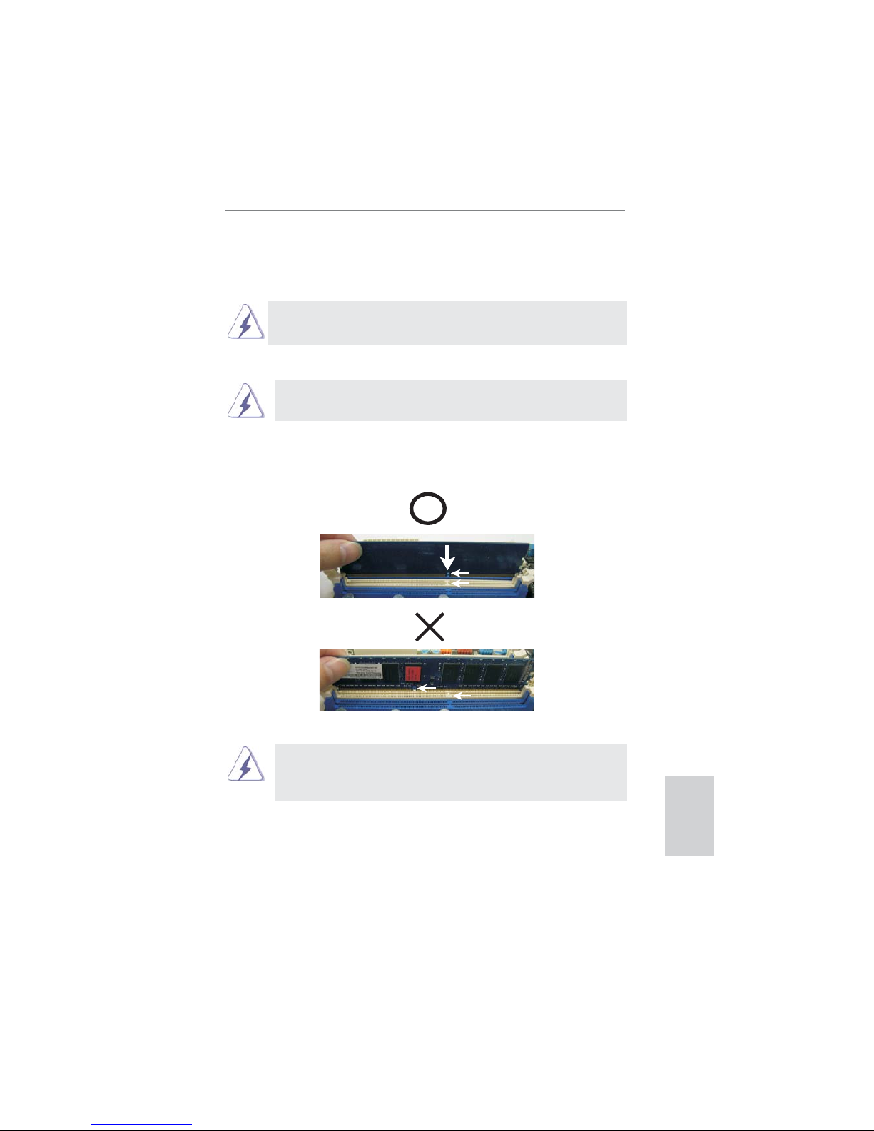
notch
break
notch
break
2.3 Installation of Memory Modules (DIMM)
E350M1/USB3 motherboard provides two 240-pin DDR3 (Double Data Rate 3)
DIMM slots.
It is not allowed to install a DDR or DDR2 memory module into DDR3
slot; otherwise, this motherboard and DIMM may be damaged.
Installing a DIMM
Please make sure to disconnect power supply before adding or
removing DIMMs or the system components.
Step 1. Unlock a DIMM slot by pressing the retaining clips outward.
Step 2. Align a DIMM on the slot such that the notch on the DIMM matches the
break on the slot.
The DIMM only fi ts in one correct orientation. It will cause permanent
damage to the motherboard and the DIMM if you force the DIMM into
the slot at incorrect orientation.
Step 3. Firmly insert the DIMM into the slot until the retaining clips at both ends
fully snap back in place and the DIMM is properly seated.

12
ASRock E350M1/USB3 Motherboard
English
2.4 Expansion Slot (PCI Express Slot)
There is 1 PCI Express slot on this motherboard.
PCIE slot:
PCIE1 (PCIE x16 slot; Blue) is used for PCI Express x4 lane width
graphics cards.
Installing an expansion card
Step 1. Before installing the expansion card, please make sure that the power
supply is switched off or the power cord is unplugged. Please read the
documentation of the expansion card and make necessary hardware
settings for the card before you start the installation.
Step 2. Remove the system unit cover (if your motherboard is already installed
in a chassis).
Step 3. Remove the bracket facing the slot that you intend to use. Keep the
screws for later use.
Step 4. Align the card connector with the slot and press fi rmly until the card is
completely seated on the slot.
Step 5. Fasten the card to the chassis with screws.
Step 6. Replace the system cover.
13
ASRock E350M1/USB3 Motherboard
English
2.5 Dual Monitor Feature
Dual Monitor Feature
This motherboard supports dual monitor feature. With the internal VGA output
support (DVI-D, D-Sub and HDMI), you can easily enjoy the benefi ts of dual monitor
feature without installing any add-on VGA card to this motherboard. This
motherboard also provides independent display controllers for DVI-D, D-Sub and
HDMI to support dual VGA output so that DVI-D, D-sub and HDMI can drive same
or different display contents.
To enable dual monitor feature, please follow the below steps:
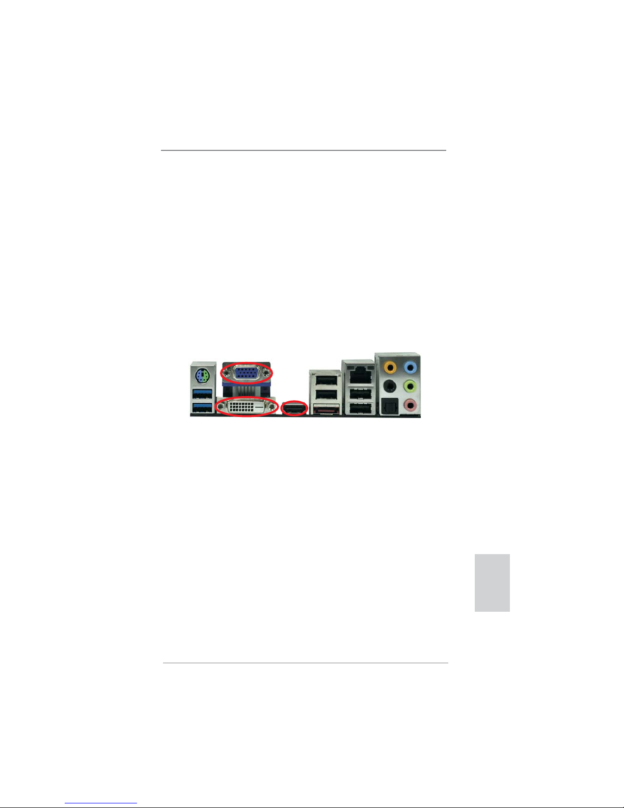
1. Connect DVI-D monitor cable to VGA/DVI-D port on the I/O panel, connect D-Sub
monitor cable to VGA/D-Sub port on the I/O panel, or connect HDMI monitor
cable to HDMI port on the I/O panel.
HDMI port
VGA/D-Sub port
VGA/DVI-D port
14
ASRock E350M1/USB3 Motherboard
English
2. If you have installed onboard VGA driver from our support CD to your system
already, you can freely enjoy the benefi ts of dual monitor function after your
system boots. If you haven’t installed onboard VGA driver yet, please install
onboard VGA driver from our support CD to your system and restart your
computer.
D-Sub, DVI-D and HDMI monitors cannot be enabled at the same time.
You can only choose the combination: DVI-D + HDMI, DVI-D + D-Sub,
or HDMI + D-Sub.

15
ASRock E350M1/USB3 Motherboard
English
HDCP Function
HDCP function is supported on this motherboard. To use HDCP
function with this motherboard, you need to adopt the monitor
that supports HDCP function as well. Therefore, you can enjoy
the superior display quality with high-defi nition HDCP
encryption contents. Please refer to below instruction for more
details about HDCP function.
What is HDCP?
HDCP stands for High-Bandwidth Digital Content Protection,
a specifi cation developed by Intel
®
for protecting digital
entertainment content that uses the DVI interface. HDCP is a
copy protection scheme to eliminate the possibility of
intercepting digital data midstream between the video source,
or transmitter - such as a computer, DVD player or set-top box and the digital display, or receiver - such as a monitor, television
or projector. In other words, HDCP specifi cation is designed to
protect the integrity of content as it is being transmitted.
Products compatible with the HDCP scheme such as DVD
players, satellite and cable HDTV set-top-boxes, as well as few
entertainment PCs requires a secure connection to a compliant
display. Due to the increase in manufacturers employing HDCP
in their equipment, it is highly recommended that the HDTV or
LCD monitor you purchase is compatible.

16
ASRock E350M1/USB3 Motherboard
English
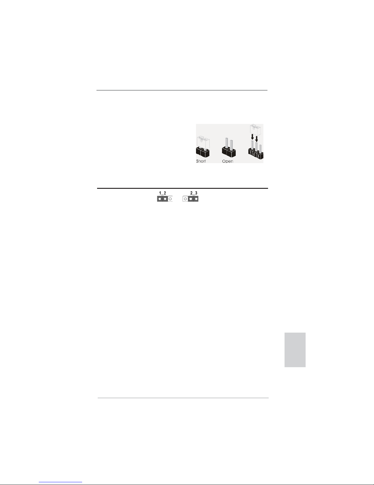
2.6 Jumpers Setup
The illustration shows how jumpers are
setup. When the jumper cap is placed on
pins, the jumper is “Short”. If no jumper cap
is placed on pins, the jumper is “Open”. The
illustration shows a 3-pin jumper whose
pin1 and pin2 are “Short” when jumper cap
is placed on these 2 pins.
Jumper Setting Description
Clear CMOS Jumper
(CLRCMOS1)
(see p.2, No. 6)
Note: CLRCMOS1 allows you to clear the data in CMOS. To clear and reset the
system parameters to default setup, please turn off the computer and unplug
the power cord from the power supply. After waiting for 15 seconds, use a
jumper cap to short pin2 and pin3 on CLRCMOS1 for 5 seconds. However,
please do not clear the CMOS right after you update the BIOS. If you need
to clear the CMOS when you just fi nish updating the BIOS, you must boot
up the system fi rst, and then shut it down before you do the clear-CMOS ac-
tion. Please be noted that the password, date, time, user default profi le, 1394
GUID and MAC address will be cleared only if the CMOS battery is removed.
Clear CMOSDefault
17
ASRock E350M1/USB3 Motherboard
English
2.7 Onboard Headers and Connectors
Onboard headers and connectors are NOT jumpers. Do NOT place
jumper caps over these headers and connectors. Placing jumper caps
over the headers and connectors will cause permanent damage of the
motherboard!
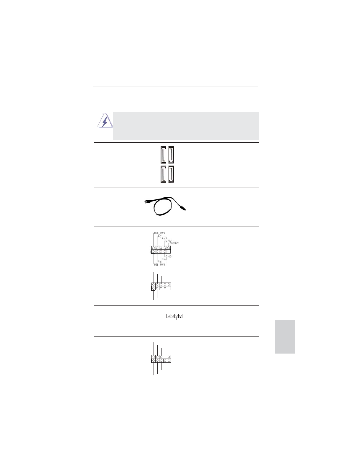
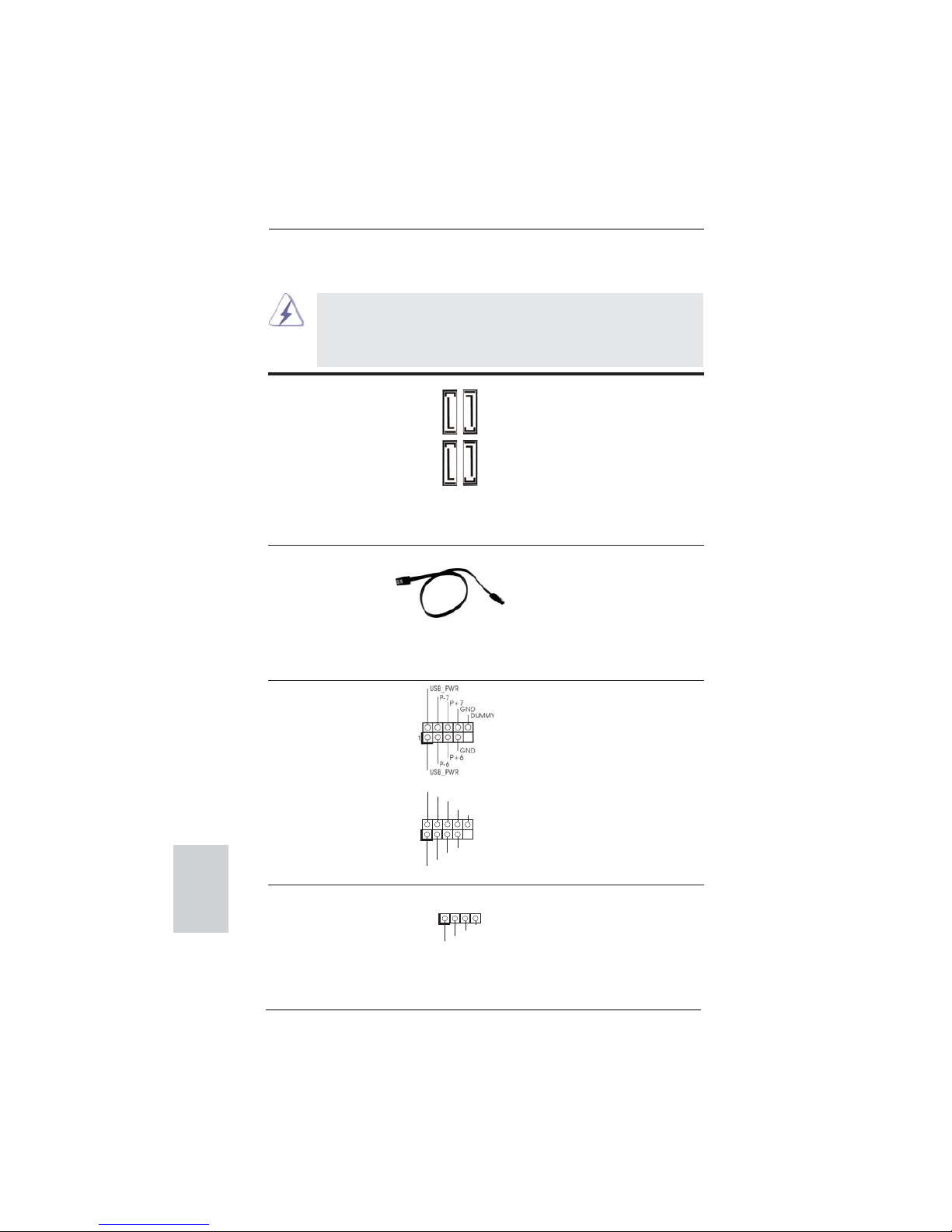
Serial ATA3 Connectors These four Serial ATA3 (SATA3)
(SATA3_1: see p.2, No. 12)
connectors support SATA data
(SATA3_2: see p.2, No. 10)
cables for internal storage
(SATA3_3: see p.2, No. 11)
devices. The current SATA3
(SATA3_4: see p.2, No. 9)
interface allows up to 6.0 Gb/s
data transfer rate.
Serial ATA (SATA) Either end of the SATA data
Data Cable cable can be connected to the
(Optional)
SATA / SATAII / SATA3 hard
disk or the SATAII / SATA3
connector on this motherboard.
USB 2.0 Headers Besides four default USB 2.0
(9-pin USB6_7)
ports on the I/O panel, there
(see p.2 No. 19)
are two USB 2.0 headers on
this motherboard. Each
USB 2.0 header can support
two USB 2.0 ports.
(9-pin USB8_9)
(see p.2 No. 18)
1
USB_PWR
P-8
GND
DUMMY
USB_PWR
P+8
GND
P-9
P+9
SATA3_4
SATA3_2
SATA3_3
SATA3_1
J_SENSE
OUT2_L
1
MIC_RET
PRESENCE#
GND
OUT2_R
MIC2_R
MIC2_L
OUT_RET
Front Panel Audio Header This is an interface for front
(9-pin HD_AUDIO1)
panel audio cable that allows
(see p.2 No. 20)
convenient connection and
control of audio devices.
Consumer Infrared Module Header This header can be used to
(4-pin CIR1)
connect the remote controller
(see p.2 No. 17)
receiver. Please refer to p. 144
for details.
1
ATX+5VSB
IRTX
GND
IRRX
18
ASRock E350M1/USB3 Motherboard
English
1. High Defi nition Audio supports Jack Sensing, but the panel wire on
the chassis must support HDA to function correctly. Please follow the
instruction in our manual and chassis manual to install your system.
2. If you use AC’97 audio panel, please install it to the front panel audio
header as below:
A. Connect Mic_IN (MIC) to MIC2_L.
B. Connect Audio_R (RIN) to OUT2_R and Audio_L (LIN) to OUT2_L.
C. Connect Ground (GND) to Ground (GND).
D. MIC_RET and OUT_RET are for HD audio panel only. You don’t
need to connect them for AC’97 audio panel.
E. To activate the front mic.
For Windows
®
XP / XP 64-bit OS:
Select “Mixer”. Select “Recorder”. Then click “FrontMic”.
For Windows® 7 / 7 64-bit / VistaTM / VistaTM 64-bit OS:
Go to the "FrontMic" Tab in the Realtek Control panel. Adjust
“Recording Volume”.
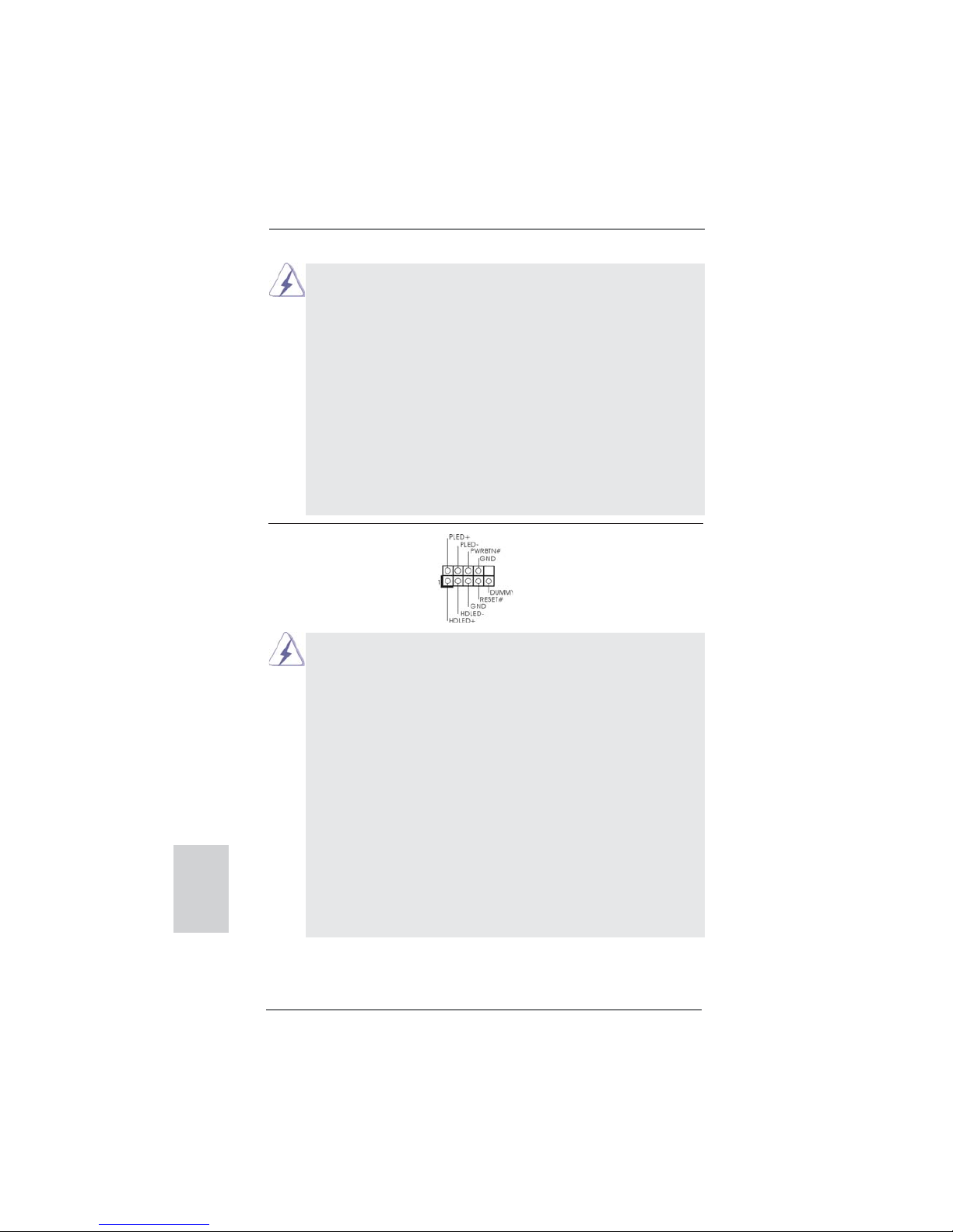
System Panel Header This header accommodates
(9-pin PANEL1)
several system front panel
(see p.2 No. 8)
functions.
Connect the power switch, reset switch and system status indicator on the
chassis to this header according to the pin assignments below. Note the
positive and negative pins before connecting the cables.
PWRBTN (Power Switch):
Connect to the power switch on the chassis front panel. You may confi gure
the way to turn off your system using the power switch.
RESET (Reset Switch):
Connect to the reset switch on the chassis front panel. Press the reset
switch to restart the computer if the computer freezes and fails to perform a
normal restart.
PLED (System Power LED):
Connect to the power status indicator on the chassis front panel. The LED
is on when the system is operating. The LED keeps blinking when the system is in S1 sleep state. The LED is off when the system is in S3/S4 sleep
state or powered off (S5).
HDLED (Hard Drive Activity LED):
Connect to the hard drive activity LED on the chassis front panel. The LED
is on when the hard drive is reading or writing data.
19
ASRock E350M1/USB3 Motherboard
English
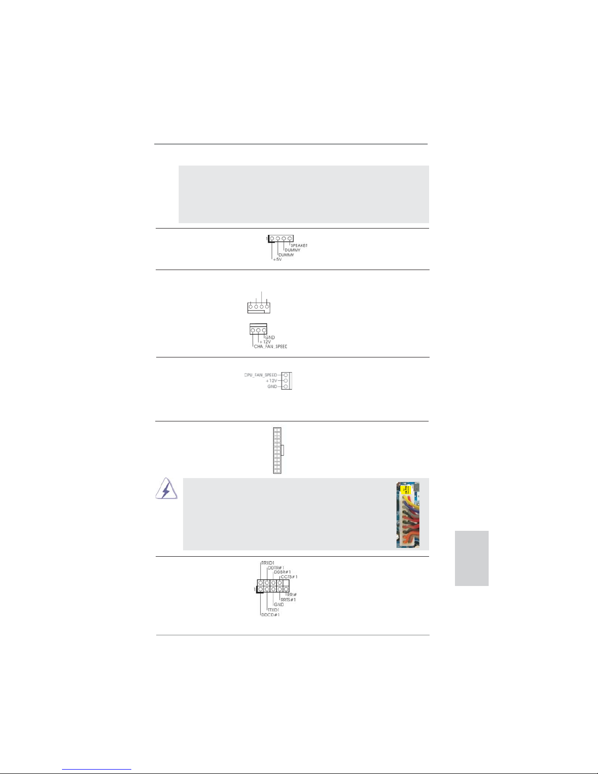
Chassis Speaker Header Please connect the chassis
(4-pin SPEAKER 1)
speaker to this header.
(see p.2 No. 13)
The front panel design may differ by chassis. A front panel module mainly
consists of power switch, reset switch, power LED, hard drive activity LED,
speaker and etc. When connecting your chassis front panel module to this
header, make sure the wire assignments and the pin assign-ments are
matched correctly.
ATX Power Connector Please connect an ATX power
(24-pin ATXPWR1)
supply to this connector.
(see p.2 No. 7)
12 124
13
20-Pin ATX Power Supply Installation
Though this motherboard provides 24-pin ATX power connector,
it can still work if you adopt a traditional 20-pin ATX power supply.
To use the 20-pin ATX power supply, please plug your
power supply along with Pin 1 and Pin 13.
12
1
24
13
Serial port Header This COM1 header supports a
(9-pin COM1)
serial port module.
(see p.2 No. 21)
GND
+12V
CHA_FAN_SPEED
FAN_SPEED_CONTROL
Chassis Fan Connectors Please connect the fan cables
(4-pin CHA_FAN1)
to the fan connectors and
(see p.2 No. 2)
match the black wire to the
ground pin. CHA_FAN2
supports fan speed control by
(3-pin CHA_FAN2)
fan power voltage.
(see p.2 No. 14)
CPU Fan Connectors Please connect the CPU fan
(3-pin CPU_FAN1)
cable to the connector and
(see p.2 No. 1)
match the black wire to the
ground pin. CPU_FAN1
supports fan speed control.

20
ASRock E350M1/USB3 Motherboard
English
2.8 Driver Installation Guide
To install the drivers to your system, please insert the support CD to your optical
drive fi rst. Then, the drivers compatible to your system can be auto-detected and
listed on the support CD driver page. Please follow the order from up to bottom side
to install those required drivers. Therefore, the drivers you install can work properly.
2.9 Installing Windows® 7 / 7 64-bit / Vista
TM
/ Vista
TM
64-bit / XP
/ XP 64-bit Without RAID Functions
If you want to install Windows® 7 / 7 64-bit / VistaTM / VistaTM 64-bit / XP / XP 64-
bit OS on your SATA / SATAII / SATA3 HDDs without RAID functions, please follow
below procedures according to the OS you install.
2.9.1 Installing Windows® XP / XP 64-bit Without RAID
Functions
If you want to install Windows® XP / XP 64-bit OS on your SATA / SATAII / SATA3
HDDs without RAID functions, please follow below steps.
STEP 1: Set up UEFI.
A. Enter UEFI SETUP UTILITY Advanced screen Storage Confi guration.
B. Set the option “SATA Mode” to [IDE].
STEP 2: Install Windows
®
XP / XP 64-bit OS on your system.
Using SATA / SATAII / SATA3 HDDs without NCQ function
AHCI mode is not supported under Windows® XP / XP 64-bit OS.
2.9.2 Installing Windows® 7 / 7 64-bit / Vista
TM
/ Vista
TM
64-bit
Without RAID Functions
If you want to install Windows® 7 / 7 64-bit / VistaTM / VistaTM 64-bit OS on your SATA
/ SATAII / SATA3 HDDs without RAID functions, please follow below steps.
Using SATA / SATAII / SATA3 HDDs with NCQ function
STEP 1: Set up UEFI.
A. Enter UEFI SETUP UTILITY Advanced screen Storage Confi guration.
B. Set the option “SATA Mode” to [AHCI].
STEP 2: Install Windows
®
7 / 7 64-bit / VistaTM / VistaTM 64-bit OS on your
system.

21
ASRock E350M1/USB3 Motherboard
English
Using SATA / SATAII / STA3 HDDs without NCQ function
STEP 1: Set up UEFI.
A. Enter UEFI SETUP UTILITY Advanced screen Storage Confi guration.
B. Set the option “SATA Mode” to [IDE].
STEP 2: Install Windows
®
7 / 7 64-bit / VistaTM / VistaTM 64-bit OS on your
system.

22
ASRock E350M1/USB3 Motherboard
English
3. BIOS Information
The Flash Memory on the motherboard stores BIOS Setup Utility. When you start up
the computer, please press <F2> or <Del> during the Power-On-Self-Test (POST)
to enter BIOS Setup utility; otherwise, POST continues with its test routines. If you
wish to enter BIOS Setup after POST, please restart the system by pressing <Ctl>
+ <Alt> + <Delete>, or pressing the reset button on the system chassis. The BIOS
Setup program is designed to be user-friendly. It is a menu-driven program, which
allows you to scroll through its various sub-menus and to select among the predetermined choices. For the detailed information about BIOS Setup, please refer to the
User Manual (PDF fi le) contained in the Support CD.
4. Software Support CD information
This motherboard supports various Microsoft
®
Windows® operating systems: 7 / 7
64-bit / VistaTM / Vista
TM
64-bit / XP / XP Media Center / XP 64-bit. The Support CD
that came with the motherboard contains necessary drivers and useful utilities that
will enhance motherboard features. To begin using the Support CD, insert the CD
into your CD-ROM drive. It will display the Main Menu automatically if “AUTORUN”
is enabled in your computer. If the Main Menu does not appear automatically, locate
and double-click on the fi le “ASSETUP.EXE” from the BIN folder in the Support CD
to display the menus.
23
ASRock E350M1/USB3 Motherboard
Deutsch
1. Einführung
Wir danken Ihnen für den Kauf des ASRock E350M1/USB3 Motherboard, ein zuverlässiges Produkt, welches unter den ständigen, strengen Qualitätskontrollen von
ASRock gefertigt wurde. Es bietet Ihnen exzellente Leistung und robustes Design,
gemäß der Verpflichtung von ASRock zu Qualität und Halbarkeit. Diese Schnellinstallationsanleitung führt in das Motherboard und die schrittweise Installation
ein. Details über das Motherboard fi nden Sie in der Bedienungsanleitung auf der
Support-CD.
Da sich Motherboard-Spezifi kationen und BIOS-Software verändern
können, kann der Inhalt dieses Handbuches ebenfalls jederzeit geändert
werden. Für den Fall, dass sich Änderungen an diesem Handbuch
ergeben, wird eine neue Version auf der ASRock-Website, ohne weitere
Ankündigung, verfügbar sein. Die neuesten Grafi kkarten und unterstützten
CPUs sind auch auf der ASRock-Website aufgelistet.
ASRock-Website: http://www.asrock.com
Wenn Sie technische Unterstützung zu Ihrem Motherboard oder spezifi sche
Informationen zu Ihrem Modell benötigen, besuchen Sie bitte unsere
Webseite:
www.asrock.com/support/index.asp
1.1 Kartoninhalt
ASRock E350M1/USB3 Motherboard
(Mini-ITX-Formfaktor: 17.0 cm x 17.0 cm; 6.7 Zoll x 6.7 Zoll)
ASRock E350M1/USB3 Schnellinstallationsanleitung
ASRock E350M1/USB3 Support-CD
Zwei Serial ATA (SATA) -Datenkabel (optional)
Ein I/O Shield
ASRock erinnert...
Zur besseren Leistung unter Windows® 7 / 7, 64 Bit / Vista
TM
/ VistaTM
64 Bit empfehlen wir, die Speicherkonfi guration im BIOS auf den AHCI-
Modus einzustellen. Hinweise zu den BIOS-Einstellungen fi nden Sie in
der Bedienungsanleitung auf der mitgelieferten CD.

24
ASRock E350M1/USB3 Motherboard
1.2 Spezifikationen
Plattform - Mini-ITX-Formfaktor: 17.0 cm x 17.0 cm; 6.7 Zoll x 6.7 Zoll
- Alle Feste Kondensatordesign (100% in Japan gefertigte,
erstklassige leitfähige Polymer-Kondensatoren)
CPU - AMD Dual-Core Zacate E350/E350D APU
- Unterstützt Cool ‘n’ Quiet
TM
-Technologie von AMD
- UMI 2.5 GT/s
Chipsatz - AMD A50M Chipsatz
Speicher - 2 x Steckplätze für DDR3
- Unterstützt DDR3 1066/800 non-ECC, ungepufferter
Speicher
- Max. Kapazität des Systemspeichers: 16GB
(siehe VORSICHT 1)
Erweiterungs- - 1 x PCI Express 2.0 x16-Steckplatz (blau für x4-Modus)
steckplätze
Onboard-VGA - Integrierte AMD Radeon HD 6310-Grafi k
- DX11 Klasse iGPU, Pixel Shader 5.0
- Maximal gemeinsam genutzter Speicher 512MB
(siehe VORSICHT 2)
- Drei VGA-Ausgangsoptionen: D-Sub, DVI-D sowie HDMI
- Unterstützt HDMI mit einer maximalen Aufl ösung von
1920 x 1200 (1080P)
- Unterstützt DVI mit einer maximalen Aufl ösung von
1920 x 1200 bei 75 Hz
- Unterstützt D-Sub mit einer maximalen Aufl ösung von
2048 x 1536 bei 85 Hz
- Unterstützt HDCP-Funktion mit DVI- und HDMI-Ports
- Unterstutzt 1080p Blu-ray (BD) / HD-DVD-Wiedergabe mit
DVI- und HDMI-Ports
Audio - 7.1
CH HD Audio mit dem Inhalt Schutz
(Realtek ALC892 Audio Codec)
- Premium Blu-ray-Audio-Unterstützung
LAN - PCIE x1 Gigabit LAN 10/100/1000 Mb/s
- Realtek RTL8111E
- Unterstützt Wake-On-LAN
- Unterstützt LAN-Kabelerkennung
- Unterstützt energieeffi zientes Ethernet 802.3az
E/A-Anschlüsse I/O Panel
an der - 1 x PS/2-Tastaturanschluss/Mausanschluss
Rückseite - 1 x VGA/D-Sub port
- 1 x VGA/DVI-D port
Deutsch
25
ASRock E350M1/USB3 Motherboard
- 1 x HDMI port
- 1 x optischer SPDIF-Ausgang
- 4 x Standard-USB 2.0-Anschlüsse
- 1 x eSATA3-Anschluss
- 2 x Standard-USB 3.0-Anschlüsse
- 1 x RJ-45 LAN Port mit LED (ACT/LINK LED und SPEED
LED)
- HD Audiobuchse: Lautsprecher hinten / Mitte/Bass /
Audioeingang / Lautsprecher vorne / Mikrofon
(siehe VORSICHT 3)
SATA3 - 4 x SATA 3-Anschlüsse (6,0 Gb/s); unterstützt NCQ-, AHCI und „Hot Plug“ (Hot-Plugging)-Funktionen
USB3.0 - 2 x USB 3.0-Ports an der Rückseite durch Etron EJ168A,
unterstützt USB 1.0/2.0/3.0 mit bis zu 5 Gb/s
Anschlüsse - 4 x SATA3 6,0 GB/s-Anschlüsse
- 1 x Consumer Infrared-Modul-Header
- 1 x COM-Anschluss-Header
- CPU/Gehäuselüfter-Anschluss
- 24-pin ATX-Netz-Header
- Anschluss für Audio auf der Gehäusevorderseite
- 2 x USB 2.0-Anschlüsse (Unterstützung 4 zusätzlicher
USB 2.0-Anschlüsse)
BIOS - 32Mb AMI BIOS
- AMIs Legal BIOS UEFI mit GUI-Unterstützung
- Unterstützung für “Plug and Play”
- ACPI 1.1-Weckfunktionen
- JumperFree-Übertaktungstechnologie
- SMBIOS 2.3.1
- DRAM, FCH, +1V, +1.8V Stromspannung Multianpassung
Support-CD - Treiber, Dienstprogramme, Anti-Virus-Software
(Testversion), ASRock Software Suite (CyberLink DVD Suite
und Creative Sound Blaster X-Fi MB) (OEM- und
Testversion)
Einzigartige - Sofortstart
Eigenschaft - ASRock Instant Flash (siehe VORSICHT 4)
- ASRock AIWI (siehe VORSICHT 5)
- ASRock APP Charger (siehe VORSICHT 6)
- SmartView (siehe VORSICHT 7)
- Hybrid Booster:
- ASRock U-COP (siehe VORSICHT 8)
- Boot Failure Guard (B.F.G. – Systemstartfehlerschutz)
Deutsch
26
ASRock E350M1/USB3 Motherboard
Deutsch
Hardware Monitor - Überwachung der CPU-Temperatur
- Motherboardtemperaturerkennung
- Drehzahlmessung für CPU/Gehäuselüfter
- Geräuscharmer CPU-/Gehäuselüfter (ermöglicht die au
tomatische Anpassung der Gehäuselüftergeschwindigkeit
durch CPU- oder MB-Temperatur)
Hardware Monitor - Überwachung der CPU-Temperatur
- Motherboardtemperaturerkennung
- Drehzahlmessung für CPU/Gehäuselüfter
- Geräuscharmer CPU-/Gehäuselüfter (ermöglicht die au
tomatische Anpassung der Gehäuselüftergeschwindigkeit
durch CPU- oder MB-Temperatur)
- Mehrstufi ge Geschwindigkeitsteuerung für CPU-/
Gehäuselüfter
- Spannungsüberwachung: +12V, +5V, +3.3V, Vcore
Betriebssysteme - Unterstützt Microsoft
®
Windows® 7 / 7 64-Bit / VistaTM /
Vista
TM
64-Bit / XP / XP Media Center / XP 64-Bit
Zertifi zierungen - FCC, CE, WHQL
- Gemäß Ökodesign-Richtlinie (ErP/EuP) (Stromversorgung
gemäß Ökodesign-Richtlinie (ErP/EuP) erforderlich)
(siehe VORSICHT 9)
* Für die ausführliche Produktinformation, besuchen Sie bitte unsere Website:
http://www.asrock.com
WARNUNG
Beachten Sie bitte, dass Overclocking, einschließlich der Einstellung im BIOS,
Anwenden der Untied Overclocking-Technologie oder Verwenden von Overclocking Werkzeugen von Dritten, mit einem gewissen Risiko behaftet ist. Overclocking kann
sich nachteilig auf die Stabilität Ihres Systems auswirken oder sogar Komponenten
und Geräte Ihres Systems beschädigen. Es geschieht dann auf eigene Gefahr und
auf Ihre Kosten. Wir übernehmen keine Verantwortung für mögliche Schäden, die
aufgrund von Overclocking verursacht wurden.

27
ASRock E350M1/USB3 Motherboard
Deutsch
VORSICHT!
1. Durch Betriebssystem-Einschränkungen kann die tatsächliche Speichergröße weniger als 4 GB betragen, da unter Windows® 7 / Vista™ / XP
etwas Speicher zur Nutzung durch das System reserviert wird. Unter
Windows
®
OS mit 64-Bit-CPU besteht diese Einschränkung nicht.
2. Die Maximalspeichergröße ist von den Chipshändler defi niert und umge-
tauscht. Bitte überprüfen Sie AMD website für die neuliche Information.
3. Der Mikrofoneingang dieses Motherboards unterstützt Stereo- und MonoModi. Der Audioausgang dieses Motherboards unterstützt 2-Kanal-,
4-Kanal-, 6-Kanal- und 8-Kanal-Modi. Stellen Sie die richtige Verbindung
anhand der Tabelle auf Seite 3 her.
4. ASRock Instant Flash ist ein im Flash-ROM eingebettetes BIOS-FlashProgramm. Mithilfe dieses praktischen BIOS-Aktualisierungswerkzeugs
können Sie das System-BIOS aktualisieren, ohne dafür zuerst Betriebssysteme wie MS-DOS oder Windows
®
aufrufen zu müssen. Mit diesem
Programm bekommen Sie durch Drücken der <F6>-Taste
während des POST-Vorgangs oder durch Drücken der <F2>-Taste im
BIOS-Setup-Menü Zugang zu ASRock Instant Flash. Sie brauchen dieses
Werkzeug einfach nur zu starten und die neue BIOS-Datei auf Ihrem
USB-Flash-Laufwerk, Diskettenlaufwerk oder der Festplatte zu speichern,
und schon können Sie Ihr BIOS mit nur wenigen Klickvorgängen ohne
Bereitstellung einer zusätzlichen Diskette oder eines anderen komplizierten Flash-Programms aktualisieren. Achten Sie darauf, dass das
USB-Flash-Laufwerk oder die Festplatte das Dateisystem FAT32/16/12
benutzen muss.
5. Das Erlebnis intuitiver, bewegungsgesteuerter Spiele ist nicht mehr
nur noch an der Wii möglich. Das ASRock AIWI-Dienstprogramm führt
eine neue Möglichkeit der PC-Spielsteuerung ein. ASRock AIWI ist das
weltweit erste Dienstprogramm, mit dem Sie Ihr iPhone/iPod touch in
einen Joystick zur Steuerung Ihrer PC-Spiele verwandeln können. Sie
müssen lediglich das ASRock AIWI-Dienstprogramm – entweder von der
offi ziellen ASRock-Webseite oder der ASRock-Software-CD Ihres Moth-
erboards – installieren sowie das kostenlose AIWI Lite vom App Store
auf Ihr iPhone/iPod touch herunterladen. Verbinden Sie Ihren PC und
das Apple-Gerät via Bluetooth oder Wi-Fi-Netzwerk – schon können Sie
die bewegungsgesteuerten Spiele genießen. Bitte denken Sie außerdem
daran, regelmäßig einen Blick auf die offi zielle ASRock-Webseite zu
werfen; wir bieten stets topaktuelle Informationen über die unterstützten
Spiele!
ASRock-Webseite: http://www.asrock.com/Feature/Aiwi/index.asp

28
ASRock E350M1/USB3 Motherboard
6. Wenn Sie nach einer schnelleren, weniger eingeschränkten Möglich-
keit zur Aufl adung Ihrer Apple-Geräte (z. B. iPhone/iPad/iPod touch)
suchen, bietet ASRock Ihnen eine wunderbare Lösung – den ASRock
APP Charger. Installieren Sie einfach den ASRock APP Charger-Treiber;
dadurch lädt sich Ihr iPhone wesentlich schneller über einen Computerauf – genaugenommen bis zu 40 % schneller als zuvor. Der ASRock APP
Charger ermöglicht Ihnen die schnelle Aufl adung mehrerer Apple-Geräte
gleichzeitig; der Ladevorgang wird sogar dann fortgesetzt, wenn der PC
den Ruhezustand (S1), Suspend to RAM-Modus (S3) oder Tiefschlafmodus (S4) aufruft oder ausgeschaltet wird (S5). Nach der Installation des
APP Charger-Treibers können Sie im Handumdrehen das großartigste
Ladeerlebnis überhaupt genießen. ASRock-Webseite: http://www.asrock.
com/Feature/AppCharger/index.asp
7.
SmartView, eine neue Internetbrowserfunktion, ist eine intelligente IEStartseite, die meist besuchte Internetseiten, Ihren Browserverlauf,
Facebook-Freunde und Nachrichten in Echtzeit miteinander kombiniert:
In einer speziellen Ansicht, die das Internet noch angenehmer und aufregender macht. ASRock-Motherboards werden exklusiv mit der SmartView-Software geliefert, die auch dafür sorgt, dass Sie immer mit Ihren
Freunden in Verbindung bleiben. Die SmartView-Funktionen können Sie
mit den Windows
®
-Betriebssystemen 7 / 7, 64 Bit / VistaTM / VistaTM 64 Bit
und dem Internet Explorer ab Version 8 nutzen. ASRock-Website: http://
www.asrock.com/Feature/SmartView/index.asp
8. Wird eine Überhitzung der CPU registriert, führt das System einen automatischen Shutdown durch. Bevor Sie das System neu starten,
prüfen Sie bitte, ob der CPU-Lüfter am Motherboard richtig funktioniert,
und stecken Sie bitte den Stromkabelstecker aus und dann wieder ein.
Um die Wärmeableitung zu verbessern, bitte nicht vergessen, etwas
Wärmeleitpaste zwischen CPU und Kühlkörper zu sprühen.
9. EuP steht für Energy Using Product und kennzeichnet die Ökodesign-Richtlinie, die von der Europäischen Gemeinschaft zur Festlegung des Energieverbrauchs von vollständigen Systemen in Kraft gesetzt wurde. Gemäß
dieser Ökodesign-Richtlinie (EuP) muss der gesamte Netzstromverbrauch
von vollständigen Systemen unter 1,00 Watt liegen,
wenn sie ausgeschaltet sind. Um dem EuP-Standard zu entsprechen,
sind ein EuP-fähiges Motherboard und eine EuP-fähige Stromversorgung
erforderlich. Gemäß einer Empfehlung von Intel muss eine EuP-fähige
Stromversorgung dem Standard entsprechen, was bedeutet, dass bei
einem Stromverbrauch von 100 mA die 5-Volt-Standby-Energieeffi zienz
höher als 50% sein sollte. Für die Wahl einer EuP-fähigen Stromversorgung
empfehlen wir Ihnen, weitere Details beim Hersteller der Stromversorgung
abzufragen.
Deutsch
29
ASRock E350M1/USB3 Motherboard
Deutsch
1.3 Einstellung der Jumper
Die Abbildung verdeutlicht, wie Jumper
gesetzt werden. Werden Pins durch
Jumperkappen verdeckt, ist der Jumper
“Gebrückt”. Werden keine Pins durch
Jumperkappen verdeckt, ist der Jumper
“Offen”. Die Abbildung zeigt einen 3-Pin
Jumper dessen Pin1 und Pin2 “Gebrückt” sind, bzw. es befi ndet sich eine
Jumper-Kappe auf diesen beiden Pins.
Jumper Einstellun Beschreibung
CMOS löschen
(CLRCMOS1, 3-Pin jumper)
(siehe S.2, No. 6)
Hinweis:
CLRCMOS1 ermöglicht Ihnen die Löschung der Daten im CMOS. Zum
Löschen und Zurücksetzen der Systemparameter auf die Standardeinrichtung
schalten Sie den Computer bitte aus und trennen das Netzkabel von der
Stromversorgung. Warten Sie 15 Sekunden, schließen Sie dann Pin2 und
Pin3 am CLRCMOS1 über einen Jumper fünf Sekunden lang kurz. Sie
sollten das CMOS allerdings nicht direkt nach der BIOS-Aktualisierung
löschen. Wenn Sie das CMOS nach Abschluss der BIOS-Aktualisierung
löschen müssen, fahren Sie zuerst das System hoch. Fahren Sie es dann
vor der CMOS-Löschung herunter. Bitte beachten Sie, dass Kennwort,
Datum, Uhrzeit, benutzerdefi niertes Profi l, 1394 GUID und MAC-Adresse
nur gelöscht werden, wenn die CMOS-Batterie entfernt wird.
CMOS
löschen
DefaultEinstellung
30
ASRock E350M1/USB3 Motherboard
Deutsch
1.4 Integrierte Header und Anschlüsse
Integrierte Header und Anschlüsse sind KEINE Jumper. Setzen Sie KEINE Jumperkappen auf diese Header und Anschlüsse. Wenn Sie Jumperkappen auf Header und Anschlüsse setzen, wird das Motherboard
unreparierbar beschädigt!
Serial ATA- (SATA-) SJedes Ende des SATA
Datenkabel Datenkabels kann an die SATA
(Option)
/ SATAII / SATA3 Festplatte
oder das SATAII / SATA3
Verbindungsstück auf
dieser Hauptplatine
angeschlossen werden.
Seriell-ATA3-Anschlüsse Diese vier Serial ATA3-
(SATA3_1: siehe S.2 - No. 12)
(SATA3-)Verbínder
(SATA3_2: siehe S.2 - No. 10)
unterstützten SATA-Datenkabel
(SATA3_3: siehe S.2 - No. 11)
für interne
(SATA3_4: siehe S.2 - No. 9)
Massenspeichergeräte. Die
aktuelle SATA3- Schnittstelle
ermöglicht eine
Datenübertragungsrate bis
6,0 Gb/s.
USB 2.0-Header Zusätzlich zu den vier
(9-pol. USB6_7)
üblichen USB 2.0-Ports an den
(siehe S.2 - No. 19)
I/O-Anschlüssen befi nden sich
zwei USB 2.0-
Anschlussleisten am
Motherboard. Pro USB 2.0-
(9-pol. USB8_9)
Anschlussleiste werden zwei
(siehe S.2 - No. 18)
USB 2.0-Ports unterstützt.
1
USB_PWR
P-8
GND
DUMMY
USB_PWR
P+8
GND
P-9
P+9
SATA3_4
SATA3_2
SATA3_3
SATA3_1
1
ATX+5VSB
IRTX
GND
IRRX
Consumer Infrared-Modul-Header Dieser Header kann zum
(4-pin CIR1)
Anschließen Remote-
(siehe S.2 - No. 17)
Empfänger. Beachten Sie den
detailliert erklärten Installation
sablauf auf Seite 144.
 Loading...