


Version 1.0
Published June 2020
This device complies with Part 15 of the FCC Rules. Operation is subject to the following two conditions:
(1)this device may not cause harmful interference, and
(2)this device must accept any interference received, including interference that may cause undesired operation.
CALIFORNIA, USA ONLY
The Lithium battery adopted on this motherboard contains Perchlorate, a toxic substance controlled in Perchlorate Best Management Practices (BMP) regulations passed by the California Legislature. When you discard the Lithium battery in California, USA, please follow the related regulations in advance.
“Perchlorate Material-special handling may apply, see www.dtsc.ca.gov/hazardouswaste/ perchlorate”

AUSTRALIA ONLY
Our goods come with guarantees that cannot be excluded under the Australian Consumer Law. You are entitled to a replacement or refund for a major failure and compensation for any other reasonably foreseeable loss or damage caused by our goods. You are also entitled to have the goods repaired or replaced if the goods fail to be of acceptable quality and the failure does not amount to a major failure.
The terms HDMI™ and HDMI High-Definition Multimedia Interface, and the HDMI logo are trademarks or registered trademarks of HDMI Licensing LLC in the United States and other countries.
Contents
Chapter 1 Introduction |
1 |
|
1.1 |
Package Contents |
1 |
1.2 |
Specifications |
2 |
Chapter 2 Product Overview |
4 |
|
2.1 |
Front View |
4 |
2.2 |
Rear View |
5 |
1.3 |
Motherboard Layout |
6 |
Chapter 3 Hardware Installation |
13 |
|
3.1 |
Begin Installation |
13 |
3.2 |
Installing the CPU |
14 |
3.3 |
Installing the CPU Fan and Heatsink |
16 |
3.4 |
Installing Memory Modules (SO-DIMM) |
17 |
3.5 |
Installing the WiFi Module |
18 |
3.6 |
Installing the M.2 SSD (Type 2280) |
19 |
3.7 |
Installing the 2.5-inch HDD/SSD |
20 |
3.8 |
Complete |
22 |
3.9 |
Installing the VESA Bracket (Optional) |
23 |
3.10 |
Installing the WiFi Antennas (Optional) |
25 |
Chapter 4 Software and Utilities Operation |
27 |
|
4.1 |
Installing Drivers |
27 |
Chapter 5 UEFI SETUP UTILITY |
28 |
|
5.1 |
Introduction |
28 |
5.2 |
EZ Mode |
29 |
5.3 |
Advanced Mode |
30 |
5.3.1 |
UEFI Menu Bar |
30 |
5.3.2 |
Navigation Keys |
31 |
5.4 |
Main Screen |
32 |
5.5 |
OC Tweaker Screen |
33 |
5.6 |
Advanced Screen |
41 |
5.6.1 |
CPU Configuration |
42 |
5.6.2 |
Chipset Configuration |
44 |
5.6.3 |
Storage Configuration |
47 |
5.6.4 |
ACPI Configuration |
48 |
5.6.5 |
USB Configuration |
49 |
5.6.6 |
Trusted Computing |
50 |
5.7 |
Tools |
52 |
5.8 |
Hardware Health Event Monitoring Screen |
54 |
5.9 |
Security Screen |
55 |
5.10 |
Boot Screen |
56 |
DeskMini H470 series
Chapter 1 Introduction
Thank you for purchasing DeskMini H470 series barebone system. In this documentation, Chapter 1 and 2 contains the introduction of the barebone system and step-by-step installation guides. Chapter 3 contains the guide of hardware installation. Chapter 4 contains the operation guide of the software and utilities. Chapter 5 contains the configuration guide of the BIOS setup.
Because the barebone system specifications and the BIOS software might be updated, the content of this documentation will be subject to change without notice.
1.1 Package Contents
•DeskMini H470 series Barebone System with: DeskMini H470 series Chassis
Motherboard (pre-installed)
*The barebone system does not include memory, hard drive, WiFi module and M.2 SSD.
•120W/19V Power Adapter & Power Cord (Optional)
•SATA Cable (Optional)
•Screws Package (HDD Screw x 6, M.2 Screw x 3pcs, Rubber Foot x 4pcs)
•Support CD (Optional)
•Quick Installation Guide (Optional)
*Package contents may vary based on local distribution.
If any items are missing or appear damaged, contact your authorized dealer.
English
1

English
1.2 Specifications
System
Model
Chassis
CPU
CPU cooling
Motherboard
Chipset
Graphics
Memory
Audio
LAN
Expansion
Slot
Front I/O
•DeskMini H470
•1.92L (155 x 155 x 80mm)
•Supports 10th Gen Intel® CoreTM Processors (Socket 1200)
•Supports Standard Intel Box Fan Coolers
•H470M-STX
•Intel® H470
•Intel® UHD Graphics
•Supports DDR4 2933MHz, 2 x SO-DIMM Slots, Max. 64GB
•Realtek ALC233 Audio Codec
•Intel Gigabit I219V LAN
•1 x M.2 Socket (Key E), supports type 2230 WiFi/BT module and Intel® CNVi (Integrated WiFi/BT)
•Power Button (with power LED & HDD LED)
•1 x USB 3.2 Gen2 (Type-A), 1 x USB 3.2 Gen1 (Type-C), 1 x Headphone/Headset Jack , 1 x MIC-In
Rear I/O |
• 1 x VGA , 1 x HDMI, 1 x DP, 4 x USB 3.2 Gen1 Type-A, 1 x |
|
USB 3.2 Gen1 Type-C , 1 x LAN, 1 x DC-In Jack |
2
Storage
Onboard
Connectors
Drive Bays
Power
Adapter
Operation
Temp.
DeskMini H470 series
•2 x SATA3 6.0 Gb/s Connectors, support RAID (RAID 0, RAID 1, Intel Rapid Storage Technology 17), NCQ, AHCI and Hot Plug
•1 x Ultra M.2 Socket, support type 2280 M.2 SATA3 6.0 Gb/s module and M.2 PCI Express module up to Gen3 x4 (32 Gb/s)*
*Supports Intel® OptaneTM Technology
*Supports NVMe SSD as boot disks
•2 x CPU Fan Connectors (2 x 4-pin)
•1 x Internal Speaker Header
•1 x Front Panel Header
•1 x USB 2.0 Header (Supports 2 USB 2.0 ports) (Supports ESD Protection)
•1 x Audio Header
•2 x 2.5" HDD or SSD
•120W/19V Power Adapter
•0~35°C
Please realize that there is a certain risk involved with overclocking, including adjusting the setting in the BIOS, applying Untied Overclocking Technology, or using third-party overclocking tools. Overclocking may affect your system’s stability, or even cause damage to the components and devices of your system. It should be done at your own risk and expense. We are not responsible for possible damage caused by overclocking.
English
3
Chapter 2 Product Overview
This chapter provides diagrams showing the location of important components of the DeskMini H470 Barebone system series.
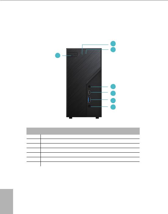
2.1 Front View
2
3
1
4
5
6
7
No. Description
1Power Button
2Power LED
3HDD LED
4MIC-In
5USB 3.2 Gen1 Type-C Port
6USB 3.2 Gen2 Type-A Port
7Headphone/Headset
English
4
DeskMini H470 series
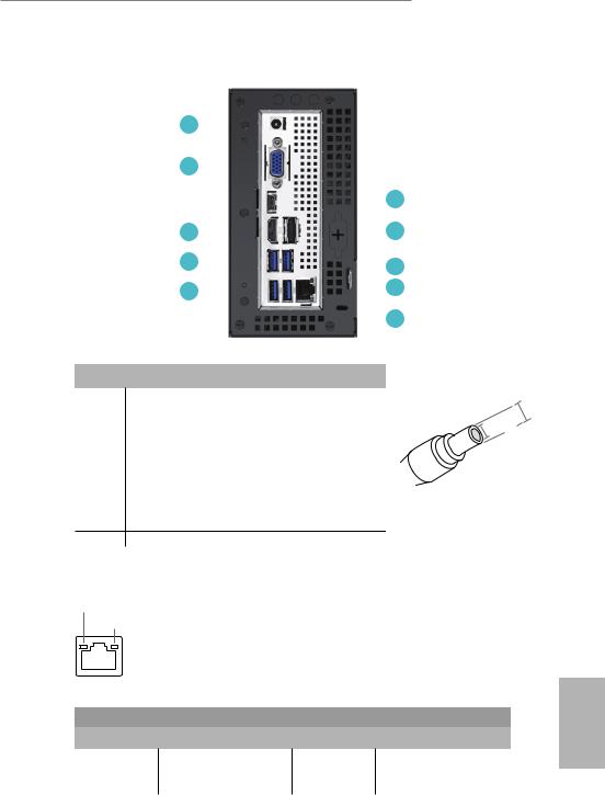
2.2 Rear View
1 |
|
|
|
|
|
|
|
|
|
|
|
|
|
|
|
|
|
|
|
|
|
2 |
|
|
|
|
|
|
|
|
|
6 |
|
|
|
|
|
|
|
|
|
||
|
|
|
|
|
|
|
|
|||
|
|
|
|
|
|
|
|
|||
3 |
|
|
|
|
|
|
|
|
7 |
|
|
|
|
|
|
|
|
|
|||
|
|
|
|
|
|
|||||
4 |
|
|
|
|
|
|
|
|
|
8 |
|
|
|
|
|
|
|
|
|
||
|
|
|
|
|
|
|
|
|
||
5 |
|
|
|
|
|
|
|
|
9 |
|
|
|
|
|
|
|
|
||||
|
|
|
|
|
|
|||||
|
|
|
|
|
|
|
|
|
10 |
|
|
|
|
|
|
|
|
|
|
||
|
|
|
|
|
|
|
|
|
||
No. |
Description |
*Specification for DC plug |
|
1 |
DC Jack (Supports 19V DC Power Adapters)* |
||
5.5 mm |
|||
2 |
D-Sub Port |
||
3 |
HDMI Port |
2.5 mm |
|
4 |
USB 3.2 Gen1 Type-A Ports |
|
|
5 |
USB 3.2 Gen1 Type-A Ports |
|
|
6 |
USB 3.2 Gen1 Type-C Port ( USB-C / DP Alt mode ) |
|
|
7 |
DisplayPort 1.4 |
|
|
8 |
LAN RJ-45 Port** |
|
|
9 |
Key Lock |
|
10Kensington Lock
**There are two LEDs on the LAN port. Please refer to the table below for the LAN port LED indications.
ACT/LINK LED
SPEED LED
LAN Port |
|
|
|
Activity / Link LED |
Speed LED |
|
|
Status |
Description |
Status |
Description |
Off |
No Link |
Off |
10Mbps connection |
Blinking |
Data Activity |
Orange |
100Mbps connection |
On |
Link |
Green |
1Gbps connection |
5
English
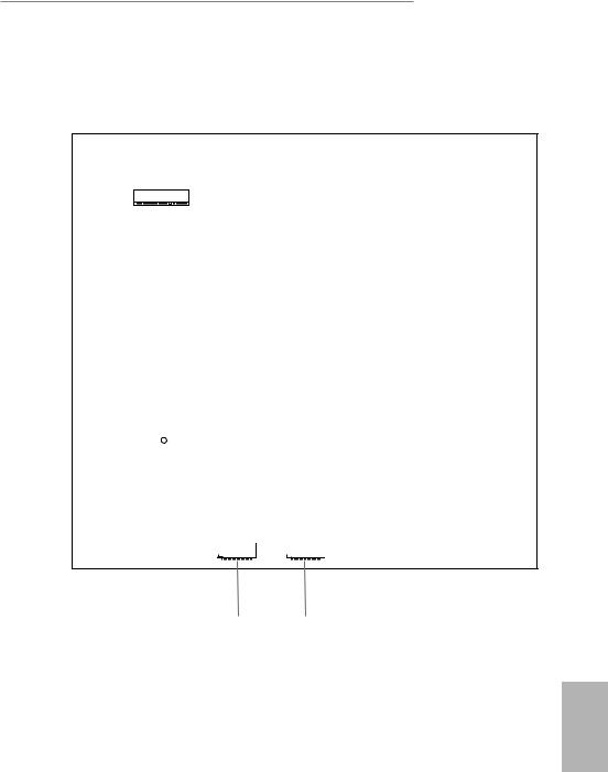
1.3 Motherboard Layout
|
|
|
|
|
|
1 |
|
2 |
|
|
|
|
|
|
|
CPU_FAN1 |
|
|
|
DC Jack |
|
|
|
|
|
|
|
|
|
VGA1 |
|
|
|
|
H470M-STX |
A1 |
|
B1 |
|
|
|
|
|
|
|
_ |
|
_ |
|
USB 3.2 Gen1 |
|
|
|
RoHS |
DDR4 |
|
DDR4 |
|
|
USB_3 |
|
|
|
|
|
|
|||
|
|
|
|
|
|
|
|
|
|
|
|
|
|
|
|
|
|
CLRMOS1 |
3 |
|
|
|
|
|
|
|
|
1 |
|
HDMI1 |
DP1 |
|
|
|
|
|
|
Mic In |
|
|
|
|
|
|
|
|
|
||
|
|
|
|
|
|
|
|
USB 3.2 Gen1 |
|
|
|
|
|
|
|
|
|
USB_2 |
|
USB 3.2 Gen1 |
|
|
|
|
|
|
|
4 |
|
T: USB_4 |
|
|
|
|
|
|
|
||
|
|
|
|
PANEL1 |
|
|
|
||
B: USB_5 |
|
|
|
USB_8_9 |
PLED PWRBTN |
|
|
|
|
|
|
|
|
|
|
|
|||
|
|
|
|
|
|
1 |
|
|
|
|
|
|
|
|
|
1 |
|
USB 3.2 Gen1 |
|
|
|
|
|
|
|
HDLED RESET |
|
USB_1 |
|
|
|
|
|
|
|
|
|
|
|
|
|
|
|
|
|
|
|
|
5 |
USB 3.2 Gen1 Top: |
|
|
|
|
|
|
|
||
T: USB_6 |
RJ-45 |
BIOS |
|
|
M2 WIFI |
M2 1 |
Headphone |
|
|
B: USB_7 |
|
ROM |
|
|
|
||||
|
|
|
|
|
Super |
/ Headset |
|
||
|
|
|
M2_1_CT1 |
M2_WIFI_CT1 |
|
|
|||
|
|
|
|
|
I/O |
|
|
||
|
CPU_FAN2 |
|
|
|
SPEAKER1 |
|
|||
|
|
|
|
|
|
|
|||
|
|
|
|
|
|
|
|
||
8 |
|
|
|
|
|
|
|
1 |
|
|
|
|
|
|
|
|
|
|
|
|
|
CMOS |
|
|
1 |
|
|
|
|
|
|
Battery |
|
|
|
AUDIO3 |
|
|
|
|
|
|
|
|
|
7 |
|
6 |
|
English
6
DeskMini H470 series
Bottom View
M2_2
SATA3 |
|
SATA3 |
|
|
|
9 |
10 |
English
7

No. Description
1CPU Fan Connector (CPU_FAN1)
22 x 260-pin DDR4 SO-DIMM Slots (DDR4_A1, DDR4_B1)
3Clear CMOS Jumper (CLRMOS1)
4System Panel Header (PANEL1)
5USB 2.0 Header (USB_8_9)
6MONO Speaker Header (SPEAKER1)
7Audio Header (AUDIO3)
8CPU Fan Connector (CPU_FAN2)
9SATA3 Connector (SATA2)
10 SATA3 Connector (SATA1)
English
8
DeskMini H470 series
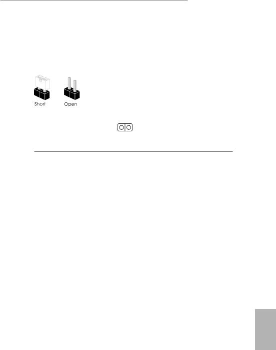
Jumpers Setup
The illustration shows how jumpers are setup. When the jumper cap is placed on the pins, the jumper is “Short”. If no jumper cap is placed on the pins, the jumper is “Open”.
Clear CMOS Jumper |
|
Short: Clear CMOS |
(CLRCMOS1) |
2-pin Jumper |
Open: Default |
(see p.6, No. 3) |
|
|
|
|
CLRCMOS1 allows you to clear the data in CMOS. The data in CMOS includes system setup information such as system password, date, time, and system setup parameters. To clear and reset the system parameters to default setup, please turn off the computer and unplug the power cord, then use a jumper cap to short the pins on CLRCMOS1 for 3 seconds. Please remember to remove the jumper cap after clearing the CMOS. If you need to clear the CMOS when you just finish updating the BIOS, you must boot up the system first, and then shut it down before you do the clear-CMOS action.
English
9
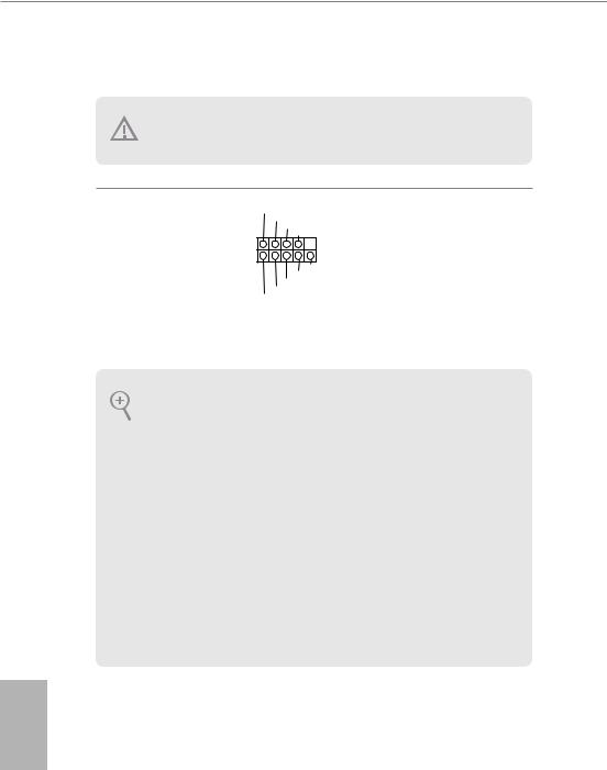
Onboard Headers and Connectors
Onboard headers and connectors are NOT jumpers. Do NOT place jumper caps over these headers and connectors. Placing jumper caps over the headers and connectors will cause permanent damage to the motherboard.
System Panel Header
(9-pin PANEL1)
(see p.6, No. 4)
PLED+ PLED-
PWRBTN#
GND
1
GND RESET#
GND HDLED-
HDLED+
Connect the power button, reset button and system status indicator on the chassis to this header according to the pin assignments below. Note the positive and negative pins before connecting the cables.
PWRBTN (Power Button):
Connect to the power button on the chassis front panel. You may configure the way to turn off your system using the power button.
RESET (Reset Button):
Connect to the reset button on the chassis front panel. Press the reset button to restart the computer if the computer freezes and fails to perform a normal restart.
PLED (System Power LED):
Connect to the power status indicator on the chassis front panel. The LED is on when the system is operating. The LED keeps blinking when the system is in S1/S3 sleep state. The LED is off when the system is in S4 sleep state or powered off (S5).
HDLED (Hard Drive Activity LED):
Connect to the hard drive activity LED on the chassis front panel. The LED is on when the hard drive is reading or writing data.
The front panel design may differ by chassis. A front panel module mainly consists of power button, reset button, power LED, hard drive activity LED, speaker and etc. When connecting your chassis front panel module to this header, make sure the wire assignments and the pin assignments are matched correctly.
English
10
DeskMini H470 series
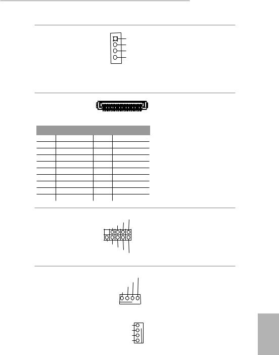
MONO Speaker Header |
1 |
|
|
|
Front_L- |
|
|
|
|||
(4-pin SPEAKER1) |
|
|
|
|
Front_L+ |
(see p.6, No. 6) |
|
|
|
|
Front_R+ |
|
|
|
|
Front_R- |
|
|
|
|
|
|
|
|
|
|
|
|
|
Please connect the chassis speaker to this header.
Serial ATA3 Connectors |
|
|
|
(see p.7, No. 9 and 10) |
1 |
20 |
|
|
|
||
PIN |
Signal Name |
PIN |
Signal Name |
1 |
GND |
11 |
N/A |
2 |
LVDS_TX+ |
12 |
5V |
3 |
LVDS_TX- |
13 |
5V |
4 |
GND |
14 |
5V |
5 |
GND |
15 |
5V |
6 |
LVDS_RX- |
16 |
5V |
7 |
LVDS_RX+ |
17 |
N/A |
8 |
GND |
18 |
GND |
9 |
GND |
19 |
GND |
10 |
GND |
20 |
GND |
These two SATA3 connectors support SATA data cables for internal storage devices with up to 6.0 Gb/s data transfer rate. *The SATA3 connectors support 2.5-inch hard drive (+5V) and do not support 3.5-inch hard drive (+12V)
USB 2.0 Header
(9-pin USB_8_9)
(see p.6, No. 5)
USB_PWR
GNDP+ P-
 1
1
DUMMY
GNDP+ P- USB_PWR
There is one header on this motherboard. This USB 2.0 header can support two ports.
CPU Fan Connectors |
FAN_SPEED_CONTROL |
This motherboard |
|||||
(4-pin CPU_FAN1) |
CPU_FAN_SPEED |
|
|
|
provides two 4-Pin CPU |
||
FAN_VOLTAGE |
|
|
|
|
|||
(see p.6, No. 1) |
GND |
|
|
|
|
fan (Quiet Fan) |
|
|
|
|
|
|
|
||
|
|
|
|
|
|
|
connectors. If you plan to |
|
|
|
|
|
|
|
|
|
1 |
2 |
3 |
4 |
|
|
connect a 3-Pin CPU fan, |
|
|
|
|
||||
|
|
|
|
|
|
|
please connect it to Pin |
(4-pin CPU_FAN2) |
FAN_SPEED_CONTROL |
|
4 |
1-3. |
|||
(see p.6, No. 8) |
FAN_SPEED |
|
|
|
3 |
|
|
FAN_VOLTAGE |
|
2 |
|
||||
|
|
|
|||||
|
|
GND |
|
1 |
|
||
English
11
Audio Header
(5-pin AUDIO3)
(see p.6, No. 7)
1


Audio-R
Audio-L Jack detect
GND
This Audio header allows you to connect the audio cable for headphone.
English
12
DeskMini H470 series
Chapter 3 Hardware Installation
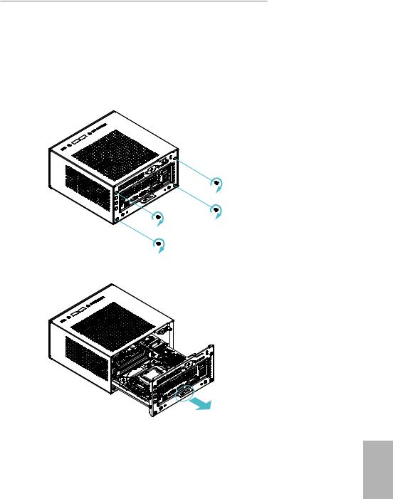
3.1 Begin Installation
1. Unscrew the four screws of the back panel.
2. Pull out the motherboard tray while holding the handle .
English
13
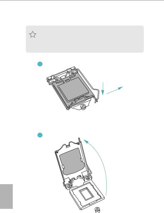
3.2Installing the CPU
1.Before you insert the 1200-Pin CPU into the socket, please check if the PnP cap is on the socket, if the CPU surface is unclean, or if there are any bent pins in the socket. Do not force to insert the CPU into the socket if above situation is found. Otherwise, the CPU will be seriously damaged.
2.Unplug all power cables before installing the CPU.
1
A
B
2
English
14
 Loading...