


Operating Instructions
HOB
|
|
|
|
|
|
|
|
|
|
|
|
|
|
|
|
|
|
Contents |
|
|
|
|
|
|
|
|
|
GB |
|
|
|
|
|
|
|
|
|
|
|
|
|
|
|
|
|
|
|
Installation, 2-5 |
|
|
GB |
|
FR |
|
|
ES |
|
|
|
|
|
|
|
Positioning |
|||||
|
|
|
|
|
|
|
|
Electrical connection |
|
|
|
|
|
|
|
|
|
||
|
English,1 |
Français, 12 |
Español, 25 |
Gas connection |
|||||
|
|
|
|
|
|
|
|
Data plate |
|
|
PT |
|
AR |
|
|
|
Burner and nozzle specifications |
||
|
|
|
|
|
Description of the appliance, 6 |
||||
|
|
|
|
|
|
|
|
||
Português, 36 |
|
|
|
|
|
||||
|
|
|
|
|
Overall view |
||||
|
|
|
|
|
|
|
|
Start-up and use, 7-8 |
|
|
|
|
|
|
|
|
|
Practical advice on using the burners |
|
|
|
|
|
|
|
|
|
Practical advice on using the electric hotplates |
|
PH 631M
PH 631MS
PH 640M GH PH 640M PH 640MS
PH 640MST GH PH 640MST
Precautions and tips, 9
General safety Disposal
Maintenance and care, 10
Switching the appliance off Cleaning the appliance Gas tap maintenance
Troubleshooting, 11
Installation
! Before operating your new appliance please read this GB instruction booklet carefully. It contains important information
for safe use, installation and care of the appliance.
! Please keep these operating instructions for future reference. Pass them on to possible new owners of the appliance.
Positioning
!Keep packaging material out of the reach of children. It can become a choking or suffocation hazard (see Precautions and tips).
!The appliance must be installed by a qualified professional according to the instructions provided. Incorrect installation may cause harm to people and animals or may damage property.
!This unit may be installed and used only in permanently ventilated rooms in accordance with British Standard Codes Of Practice: B.S. 6172 / B.S. 5440, Par. 2 and B.S. 6891 Current Editions. The following requirements must be observed:
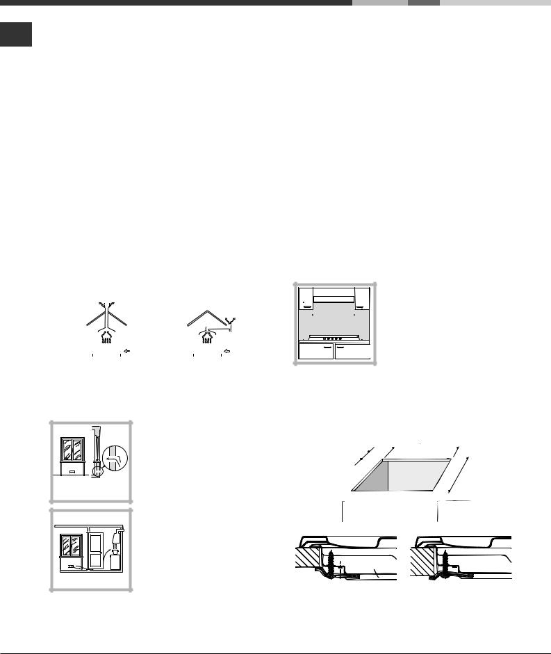
•The room must be equipped with an air extraction system that expels any combustion fumes. This may consist of a hood or an electric fan that automatically starts each time the appliance is switched on.
|
|
|
|
|
|
|
|
|
|
|
|
|
|
|
|
|
|
|
|
|
|
|
|
|
|
|
|
|
|
|
|
|
|
|
|
|
|
|
|
|
|
|
|
|
|
|
|
|
|
|
|
|
|
|
|
|
|
|
|
|
|
|
|
|
|
|
|
|
|
|
|
|
|
|
|
|
|
|
|
|
|
|
|
|
|
|
|
|
|
|
|
|
|
|
|
|
|
|
|
|
|
|
|
|
|
|
|
|
|
|
|
|
|
|
|
|
|
|
|
|
|
|
|
|
|
In a chimney stack or branched flue. |
Directly to |
|
|
|
|
|||||||||||||||
(exclusively for cooking appliances) |
the Outside |
|
|
|
|
|||||||||||||||
|
|
|
|
|
|
|
|
|
|
|
|
|
|
|
|
|
|
|
|
|
•The room must also allow proper air circulation, as air is needed for combustion to occur normally. The flow of air
must not be less than 2 m3/h per kW of installed power. The air circulation system may
take air directly from the outside
by means of a pipe with an inner
cross section of at least 100 cm2; the opening must not be vulnerable to any type of blockages.
Adjacent |
Room to be |
Room |
Vented |
Enlarging the ventilation slot |
|
between window and floor. |
|
The system can also provide the air needed for combustion indirectly, i.e. from adjacent rooms fitted with air circulation tubes as described above. However, these rooms must not be communal rooms, bedrooms or rooms that may present a fire hazard.
•Liquid petroleum gas sinks to the floor as it is heavier than air. Therefore, rooms containing LPG cylinders must
also be equipped with vents to allow gas to escape in the event of a leak. As a result LPG cylinders, whether partially or completely full, must not be installed or stored in rooms or storage areas that are below ground level (cellars, etc.). It is advisable to keep only the cylinder being used in the room, positioned so that it is not subject to heat produced by external sources (ovens, fireplaces, stoves, etc. ) which could raise the temperature of the cylinder above 50°C.
Fitting the appliance
Gas and mixed hobs are manufactured with type X degree protection against overheating. The following precautions must be taken when installing the hob:
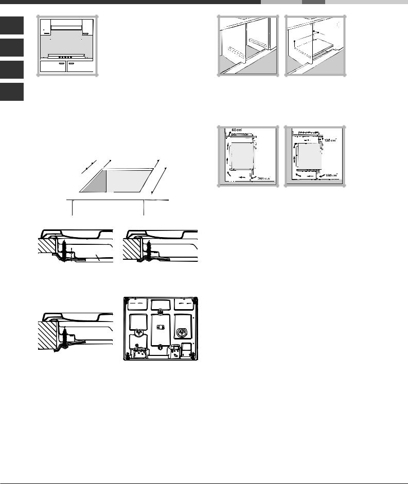
•Kitchen cabinets adjacent to the appliance and taller than the top of the hob must be at least 600 mm from the edge of the hob.
•Hoods must be installed according to their relative installation instruction manuals and at a minimum distance of 650 mm from the hob.
•Place the wall cabinets adjacent to the hood at a minimum height of 420 mm from the hob (see figure).
|
600mm min. |
700mmmin. |
600mmmin. |
If the hob is installed beneath a wall cabinet, the latter must be situated at a minimum of 700 mm above the hob (see figure).
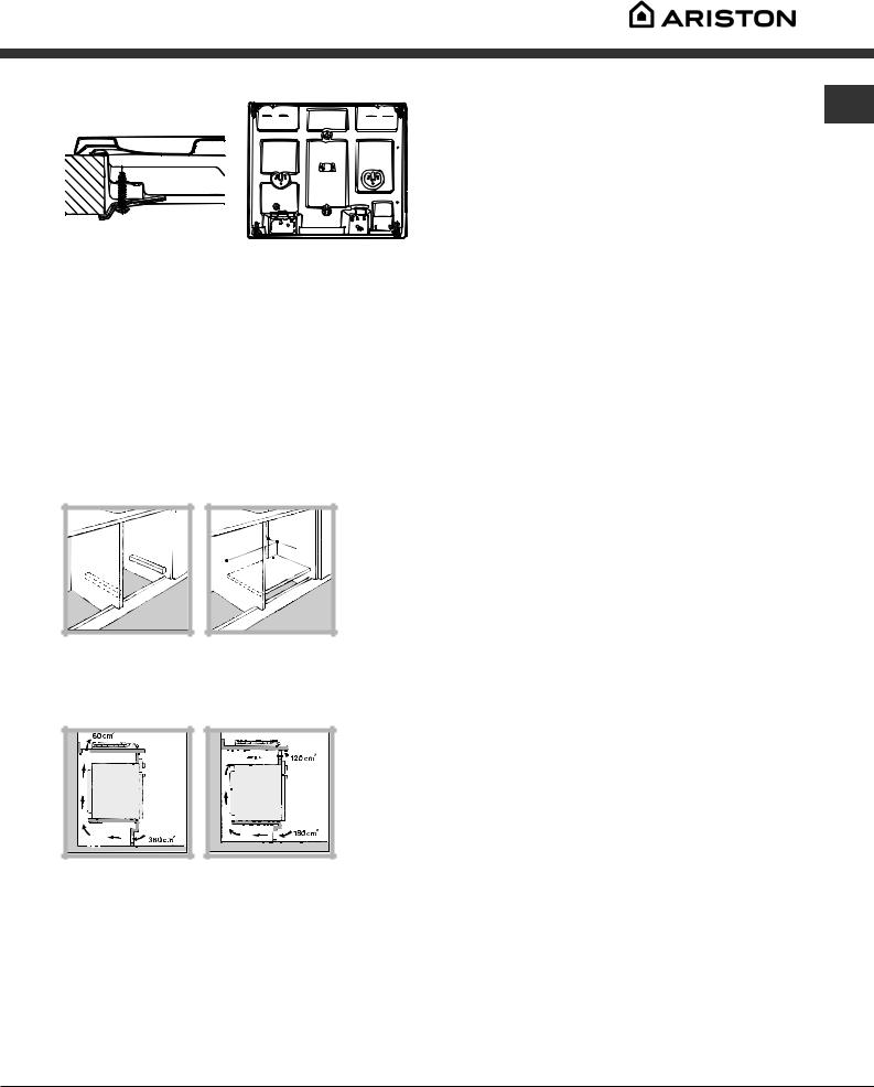
•The installation cavity should have the dimensions indicated in the figure.
Fastening hooks are provided, allowing you to fasten the hob to tops that are between 20 and 40 mm thick. To ensure the hob is securely fastened to the top, we recommend you use all the hooks provided.
|
|
|
|
555 mm |
|
|
|
||||
|
|
|
|
|
|
|
|
|
|
|
|
|
mm |
|
|
|
|
|
|
|
|
|
|
55 |
|
|
|
|
|
|
|
m |
m |
||
|
|
|
|
|
|
|
|
||||
|
|
|
475 |
|
|
||||||
|
|
|
|
|
|
||||||
|
|
|
|
|
|
|
|||||
|
|
|
|
|
|
|
|
|
|
|
|
Hook fastening diagram
Hooking position |
Hooking position |
for top H=20 mm |
for top H=30 mm |
2
Front
Hooking position |
Back |
for top H=40 mm |
|
! Use the hooks contained in the “accessory pack”
•Where the hob is not installed over a built-in oven, a wooden panel must be installed as insulation. This must be placed at a minimum distance of 20 mm from the lower part of the hob.
Ventilation
To ensure adequate ventilation, the back panel of the cabinet must be removed. It is advisable to install the oven so that it rests on two strips of wood, or on a completely flat surface with an opening of at least 45 x 560 mm (see diagrams).
. |
45 |
mm |
. |
mm |
|
||
560 |
|
|
|
When installing the cooktop above a built-in oven without forced ventilation, ensure that there are air inlets and outlets for ventilating the interior of the cabinet adequately.
Electrical connection
Hobs equipped with a three-pole power supply cable are designed to operate with alternating current at the voltage and frequency indicated on the data plate (this is located on the lower part of the appliance). The earth wire in the cable has a green and yellow cover. If the appliance is to be installed above a built-in electric oven, the electrical connection of the hob and the oven must be carried out separately, both for electrical safety purposes and to make extracting the oven easier.
Connecting the supply cable to the mains
Install a standardised plug corresponding to the load |
GB |
|
|
indicated on the data plate. |
|
The appliance must be directly connected to the mains using |
|
an omnipolar circuit-breaker with a minimum contact opening |
|
of 3 mm installed between the appliance and the mains. The |
|
circuit-breaker must be suitable for the charge indicated and |
|
must comply with current electrical regulations (the earthing |
|
wire must not be interrupted by the circuit-breaker). The |
|
supply cable must not come into contact with surfaces with |
|
temperatures higher than 50°C. |
|
! The installer must ensure that the correct electrical |
|
connection has been made and that it is compliant with |
|
safety regulations. |
|
Before connecting to the power supply, make sure that: |
|
•The appliance is earthed and the plug is compliant with the law.
•The socket can withstand the maximum power of the appliance, which is indicated on the data plate.
•The voltage is in the range between the values indicated on the data plate.
•The socket is compatible with the plug of the appliance. If the socket is incompatible with the plug, ask an authorised technician to replace it. Do not use extension cords or multiple sockets.
!Once the appliance has been installed, the power supply cable and the electrical socket must be easily accessible.
!The cable must not be bent or compressed.
!The cable must be checked regularly and replaced by authorised technicians only (see Assistance).
!The manufacturer declines any liability should these safety measures not be observed.
Gas connection
The appliance should be connected to the main gas supply or to a gas cylinder in compliance with current national regulations. Before carrying out the connection, make sure the cooker is compatible with the gas supply you wish to use. If this is not the case, follow the instructions indicated in the paragraph “Adapting to different types of gas.”
When using liquid gas from a cylinder, install a pressure regulator which complies with current national regulations.
! Check that the pressure of the gas supply is consistent with the values indicated in Table 1 (“Burner and nozzle specifications”). This will ensure the safe operation and longevity of your appliance while maintaining efficient energy consumption.
Connection with a rigid pipe (copper or steel)
! Connection to the gas system must be carried out in such a way as not to place any strain of any kind on the appliance.
There is an adjustable L-shaped pipe fitting on the
3
appliance supply ramp and this is fitted with a seal in GB order to prevent leaks. The seal must always be replaced
after rotating the pipe fitting (seal provided with appliance). The gas supply pipe fitting is a threaded 1/2 gas cylindrical male attachment.
Connecting a flexible jointless stainless steel pipe to a threaded attachment
The gas supply pipe fitting is a threaded 1/2 gas cylindrical male attachment.
These pipes must be installed so that they are never longer than 2000 mm when fully extended. Once connection has been carried out, make sure that the flexible metal pipe does not touch any moving parts and is not compressed.
! Only use pipes and seals that comply with current national regulations.
Checking the tightness of the connection
! When the installation process is complete, check the pipe fittings for leaks using a soapy solution. Never use a flame.
Adapting to different types of gas
To adapt the hob to a different type of gas other than default type (indicated on the rating plate at the base of the hob or on the packaging), the burner nozzles should be replaced as follows:
1.Remove the hob grids and slide the burners off their seats.
2.Unscrew the nozzles using a 7 mm socket spanner, and replace them with nozzles for the new type of gas (see table 1 “Burner and nozzle characteristics”).
3.Reassemble the parts following the above procedure in the reverse order.
4.Once this procedure is finished, replace the old rating sticker with one indicating the new type of gas used. Sticker are available from any of our Service Centres.
•Adjusting the burners’ primary air : Does not require adjusting.
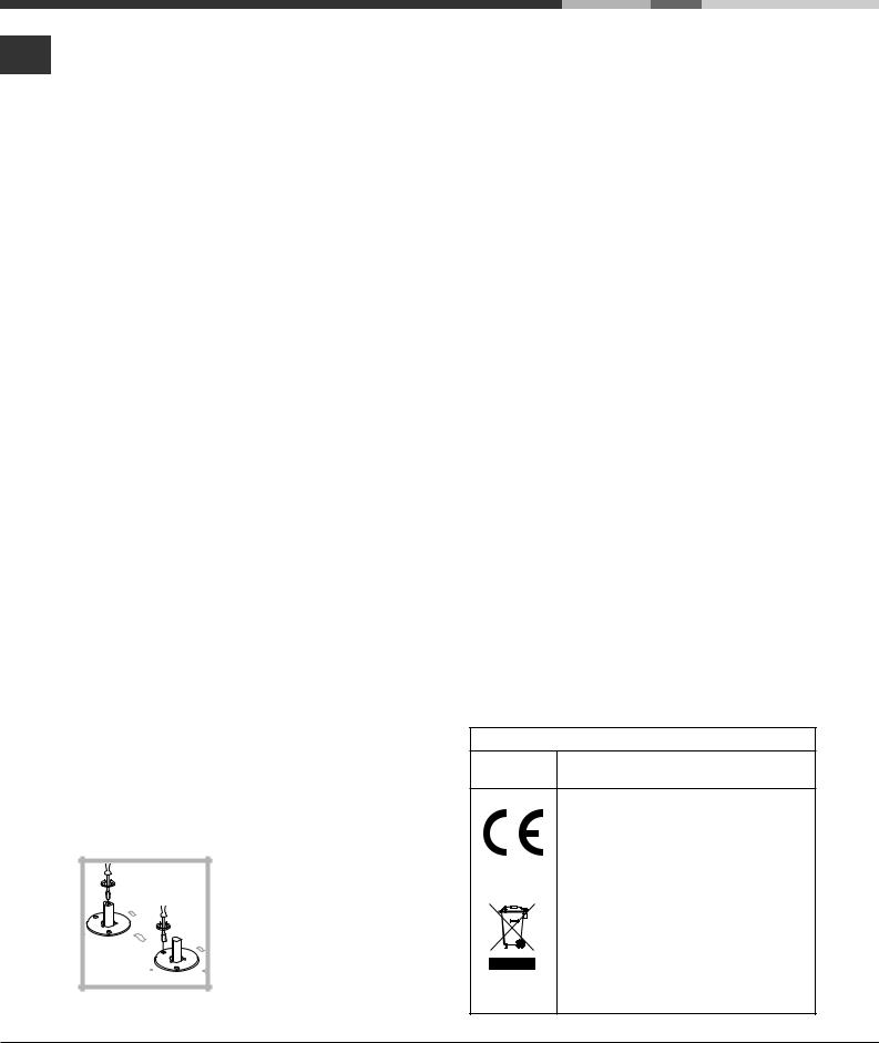
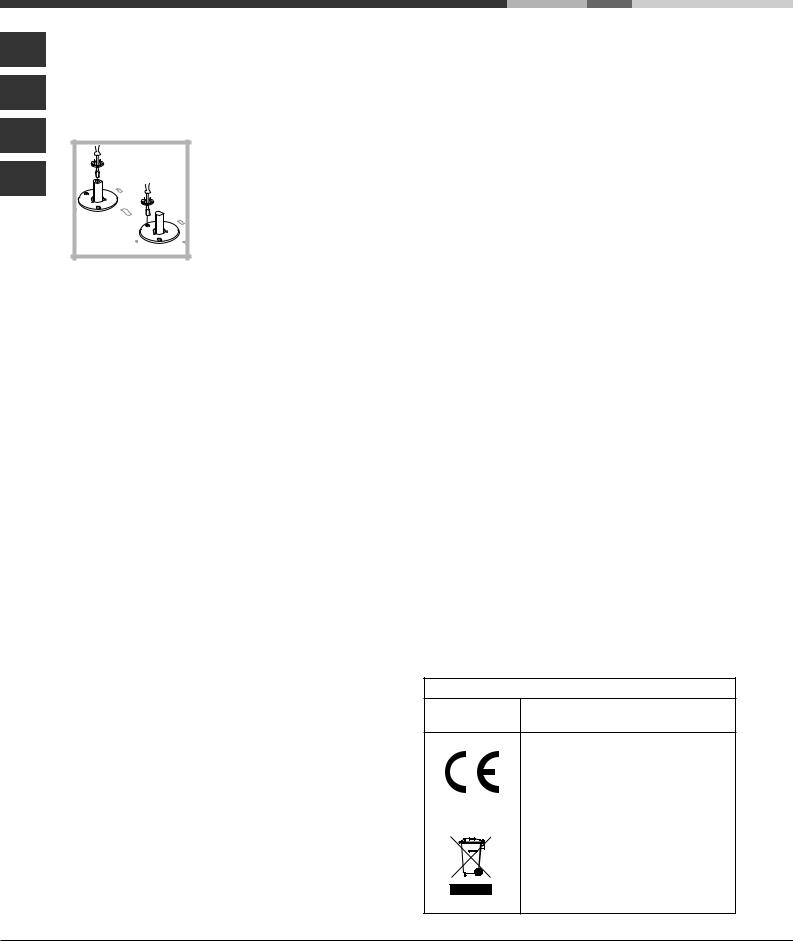
•Setting the burners to minimum:
1.Turn the tap to the low flame position.
2.Remove the knob and adjust the adjustment screw, which is positioned in or next to the tap pin, until the flame is small but steady.
3.Having adjusted the flame to the required low setting, while the burner is alight, quickly change the position of the knob from minimum to maximum and vice versa several times, checking that the flame does not go out.
4.Some appliances have a safety device (thermocouple) fitted. If the device fails to work when the burners are set to the low flame setting, increase this low flame setting using the adjusting screw.
5.Once the adjustment has been made, replace the seals on the by-passes using sealing wax or a similar substance.
!If the appliance is connected to liquid gas, the regulation screw must be fastened as tightly as possible.
!Once this procedure is finished, replace the old rating sticker with one indicating the new type of gas used. Stickers are available from any of our Service Centres.
!Should the gas pressure used be different (or vary slightly) from the recommended pressure, a suitable pressure regulator must be fitted to the inlet pipe (in order to comply with current national regulations).
DATA PLATE
Electrical
connections see data plate
This appliance conforms to the following
European Economic Community directives:
-2006/95/EEC dated 12/12/06 (Low Voltage) and subsequent amendments
-2004/108/EEC dated 15/12/04 (Electromagnetic Compatibility) and subsequent amendments
- 93/68/EEC dated 22/07/93 and subsequent amendments.
- 2009/142/EEC dated 30/11/09 (Gas) and subsequent amendments.
- 2002/96/EC and subsequent amendments.
4
 User Manual")
Burner and nozzle specifications
|
|
|
|
|
|
|
|
|
|
|
|
|
|
|
|
GB |
|
|
|
|
|
|
|
|
|
|
|
|
|
|
|
|
|
Table 1 |
|
|
|
|
|
|
|
Liquid Gas |
|
|
|
Naturale Gas |
||||
|
|
|
|
|
|
|
|
|
|
|
|
|
|
|||
Burner |
Diameter |
Thermal Power |
By-pass |
|
Nozzle |
Flow* |
Nozzle |
|
Flow* |
|||||||
|
(mm) |
kW (p.c.s.*) |
|
1/100 |
|
1/100 |
g/h |
|
1/100 |
|
l/h |
|||||
|
|
|
|
|
|
(mm) |
|
|
|
|
|
|
|
|
|
|
|
|
Nom. |
|
Red. |
|
|
(1) |
|
(mm) |
*** |
|
** |
(mm) |
|
|
|
|
|
|
|
|
|
|
|
|
|
|||||||
|
|
|
|
|
|
|
|
|
|
|
|
|
|
|
|
|
Fast |
100 |
3.00 |
|
0.70 |
41 |
|
39 |
|
86 |
218 |
|
214 |
116 |
|
286 |
|
(Large) (R) |
|
|
|
|
|
|
||||||||||
|
|
|
|
|
|
|
|
|
|
|
|
|
|
|
|
|
|
|
|
|
|
|
|
|
|
|
|
|
|
|
|
|
|
Reduced Fast |
100 |
2.60 |
|
0.70 |
41 |
|
39 |
|
80 |
189 |
|
186 |
110 |
|
248 |
|
(RR) |
|
|
|
|
|
|
||||||||||
|
|
|
|
|
|
|
|
|
|
|
|
|
|
|
|
|
|
|
|
|
|
|
|
|
|
|
|
|
|
|
|
|
|
Semi Fast |
75 |
1.65 |
|
0.40 |
30 |
|
28 |
|
64 |
120 |
|
118 |
96 |
|
157 |
|
(Medium) (S) |
|
|
|
|
|
|
||||||||||
|
|
|
|
|
|
|
|
|
|
|
|
|
|
|
|
|
|
|
|
|
|
|
|
|
|
|
|
|
|
|
|
|
|
Auxiliary |
55 |
1.00 |
|
0.40 |
30 |
|
28 |
|
50 |
73 |
|
71 |
71 |
|
95 |
|
(Small) (A) |
|
|
|
|
|
|
||||||||||
|
|
|
|
|
|
|
|
|
|
|
|
|
|
|
|
|
|
|
|
|
|
|
|
|
|
|
|
|
|
|
|
|
|
Triple Crown |
130 |
3.25 |
|
1.50 |
60 |
|
61 |
|
91 |
236 |
|
232 |
133 |
|
309 |
|
(TC) |
|
|
|
|
|
|
||||||||||
|
|
|
|
|
|
|
|
|
|
|
|
|
|
|
|
|
|
|
|
|
|
|
|
|
|
|
|
|
|
|
|
|
|
Supply |
Nominal (mbar) |
|
|
|
|
|
|
28-30 |
|
37 |
|
20 |
|
|||
pressures |
Minimum (mbar) |
|
|
|
|
|
20 |
|
25 |
|
17 |
|
||||
|
Maximum (mbar) |
|
|
|
|
|
35 |
|
45 |
|
25 |
|
||||
*At 15°C and 1013 mbar-dry gas
** |
Propane |
P.C.S. = 50.37 MJ/kg. |
|
|
|
|
|
|
|||
*** |
Butane |
P.C.S. = 49.47 MJ/kg. |
|
|
|
|
|
|
|||
Natural |
P.C.S. = 37.78 MJ/m3 |
|
|
|
|
|
|
|
|||
(1) Only for appliances with the security device. |
|
|
|
|
|
|
|||||
Table 1 (For Hungary) |
|
G 20 |
|
G 25.1 |
G 30 |
||||||
Burner |
|
|
By-pass |
Thermal |
Nozzle |
Thermal |
Nozzle |
Thermal |
Nozzle |
||
|
|
|
|
1/100 (mm) |
Power kW |
1/100 (mm) |
Power kW |
1/100 (mm) |
Power kW |
1/100 (mm) |
|
Fast (R) |
|
|
3.00 |
2,90 |
116 |
|
2,25 |
116 |
2,70 |
86 |
|
Reduced Fast (RR) |
2.60 |
2,45 |
110 |
|
1,90 |
110 |
2,30 |
80 |
|||
Semi Fast (Medium) (S) |
1.65 |
1,60 |
96 |
|
1,25 |
96 |
1,50 |
64 |
|||
Auxiliary (Small) (A) |
1.00 |
0,90 |
71 |
|
0,65 |
71 |
0,90 |
50 |
|||
Triple Crown (TC) |
3.25 |
3,15 |
133 |
|
2,45 |
133 |
2,90 |
91 |
|||
Supply pressures |
|
25 mbar |
|
25 mbar |
30 mbar |
||||||
At 15°C and 1013 mbar-dry gas |
P.C.I. G30 |
122,8 MJ/m3 |
|
|
|
||||||
P.C.I. G20 |
|
35,9 MJ/m3 |
P.C.I. G25.1 |
30,9 MJ/m3 |
|
|
|
||||
|
A |
|
|
|
A |
|
|
|
|
|
|
|
R |
|
S |
RR |
TC |
|
|
R |
S |
|
|
|
S |
|
|
|
S |
|
|
S |
|
|
|
PH 640.../HA |
|
|
PH 640MST.../HA |
|
PH 631.../HA |
|
|
|
|||
5
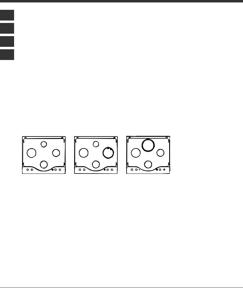
Description of the appliance
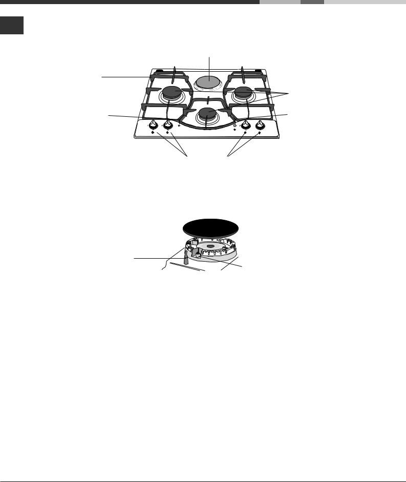
Overall view
GB
ELECTRIC HOTPLATES*
Support Grid for
COOKWARE
Indicator Light for |
|
|
ELECTRIC HOTPLATES* |
6 |
1 |
|
5 |
2 |
|
4 |
3 |
Control Knobs for
GAS BURNERS and
ELECTRIC HOTPLATES*
GAS BURNERS
Ignition Button for GAS
BURNERS*
SAFETY |
|
DEVICES* |
Ignition for |
|
GAS BURNERS* |
•The INDICATOR LIGHT FOR ELECTRIC HOTPLATES* switches on whenever the selector knob is moved from the ‘off’ position.
•GAS BURNERS differ in size and power. Use the diameter of the cookware to choose the most appropriate burner to cook with.
•Control Knobs for GAS BURNERS and ELECTRIC PLATES* adjust the power or the size of the flame.
•GAS BURNER ignition* enables a specific burner to be lit automatically.
•SAFETY DEVICE* stops the gas flow if the flame is accidentally extinguished.
* Only available on certain models.
6

Start-up and use
! The position of the corresponding gas burner or electric hotplate* is shown on every knob.
Gas burners
Each burner can be adjusted to one of the following settings using the corresponding control knob:
•Off
Maximum
Minimum
To light one of the burners, hold a lit match or lighter near the burner and, at the same time, press down and turn the corresponding knob anti-clockwise to the maximum setting.
Since the burner is fitted with a safety device, the knob should be pressed for approximately 2-3 seconds to allow the automatic device keeping the flame alight to heat up.
When using models with an ignition button, light the desired burner by first pressing the gas burners
button (identifiable by the  symbol), then pressing down the corresponding knob as far as possible and turning it anticlockwise towards the maximum setting. Some models are equipped with an ignition switch incorporated into the control knob. If this is the case, the ignitor is present, but not the switch (the
  symbol is located near each knob).
To light a burner, simply press the corresponding knob all the way in and then turn it in the counterclockwise direction to the "High" setting, keeping it pressed in until the burner lights.
! If a flame is accidentally extinguished, turn off the control knob and wait for at least 1 minute before trying to relight it.
To switch off the burner, turn the knob in a clockwise direction until it stops (when reaches the “•” position).
Electric hotplates*
GB
The corresponding knob may be turned clockwise or anti-clockwise and set to six different positions:
Setting |
Normal or Fast Plate |
|
|
0 |
Off |
|
|
1 |
Low |
|
|
2 - 5 |
Medium |
|
|
6 |
High |
|
|
When the selector knob is in any position other than the off position, the ‘on’ light comes on.
Practical advice on using the burners
To ensure the burners operate efficiently:
•Use appropriate cookware for each burner (see table) so that the flames do not extend beyond the bottom of the cookware.
•Always use cookware with a flat base and a cover.
•When the contents of the pan reach boiling point, turn the knob to minimum.
Burner |
Ø Cookware Diameter (cm) |
|
|
Fast (R) |
24 - 26 |
|
|
Reduced Fast (RR) |
22 - 24 |
|
|
Semi Fast (S) |
16 - 20 |
|
|
Auxiliary (A) |
10 - 14 |
|
|
Triple Crown (TC) |
24 - 26 |
|
|
* Only available on certain models.
7

Practical advice on using the electric
GB hotplates
To avoid heat loss and damage to the hotplates, use pans with a flat base, whose diameter is no less than that of the hotplate itself.
Setting |
Setting |
|
|
0 |
Off |
|
|
1 |
Cooking vegetables, fish |
|
|
2 |
Cooking patatoes (using steam) soups, |
|
chickpeas, beans. |
|
|
3 |
Continuing the cooking of large quantities of |
|
food, minestrone. |
|
|
4 |
For roasting (average) |
|
|
5 |
For roasting (above average) |
|
--------- |
6 |
For browning and reaching a boil in a short |
|
time |
|
|
! Before using the hotplates for the first time, you should heat them at maximum temperature for approximately 4 minutes, without placing any pans on them. During this initial stage, their protective coating hardens and reaches its maximum resistance.
* Only available on certain models.
8

Precautions and tips
! This appliance has been designed and manufactured in compliance with international safety standards. The following warnings are provided for safety reasons and must be read carefully.
General safety
•This is a class 3 built-in appliance.
•Gas appliances require regular air exchange to maintain efficient operation. When installing the hob, follow the instructions provided in the paragraph on “Positioning” the appliance.
•These instructions are only valid for the countries whose symbols appear in the manual and on the serial number plate.
•The appliance was designed for domestic use inside the home and is not intended for commercial or industrial use.
•The appliance must not be installed outdoors, even in covered areas. It is extremely dangerous to leave the appliance exposed to rain and storms.
•Do not touch the appliance with bare feet or with wet or damp hands and feet.
•The appliance must be used by adults only for the preparation of food, in accordance with the instructions outlined in this booklet. Any other use of the appliance (e.g. for heating the room) constitutes improper use and is dangerous.
The manufacturer may not be held liable for any damage resulting from improper, incorrect and unreasonable use of the appliance.
•Ensure that the power supply cables of other electrical appliances do not come into contact with the hot parts of the oven.
•The openings used for ventilation and dispersion of heat must never be covered.
•Always make sure the knobs are in the “”/“” position when the appliance is not in use.
•When unplugging the appliance always pull the plug from the mains socket, do not pull on the cable.
•Never carry out any cleaning or maintenance work without having detached the plug from the mains.
•In case of malfunction, under no circumstances should you attempt to repair the appliance yourself. Repairs carried out by inexperienced persons may cause injury or further malfunctioning of the appliance. Contact a Service Centre (see Assistance).
•Always make sure that pan handles are turned towards the centre of the hob in order to avoid accidental burns.
•Do not close the glass cover (if present) when the gas burners or electric hotplates are still hot.
• Do not leave the electric hotplate switched on |
GB |
without a pan placed on it. |
•Do not use unstable or deformed pans.
•The appliance should not be operated by people (including children) with reduced physical, sensory or mental capacities, by inexperienced individuals or by anyone who is not familiar with the product. These individuals should, at the very least, be supervised by someone who assumes responsibility for their safety or receive preliminary instructions relating to the operation of the appliance.
•Do not let children play with the appliance.
•The appliance is not intended to be operated by means of an external timer or separate remote-control system.
Disposal
•When disposing of packaging material: observe local legislation so that the packaging may be reused.
•The European Directive 2002/96/EC on Waste Electrical and Electronic Equipment (WEEE), requires that old household electrical appliances must not be disposed of in the normal unsorted municipal waste stream. Old appliances must be collected separately in order to optimise the recovery and recycling of the materials they contain and reduce the impact on human health and the environment. The crossed out “wheeled bin” symbol on the product reminds you of your obligation, that when you dispose of the appliance it must be separately collected. Consumers may take their old appliance to public waste collection areas, other communal collection areas, or if national legislation allows return it to a retailer when purchasing a similar new product. All major household appliance manufacturers are active in the creation of systems to manage the collection and disposal of old appliances.
9

Maintenance and care
Switching the appliance off
GB
Disconnect your appliance from the electricity supply before carrying out any work on it.
Cleaning the appliance
!Do not use abrasive or corrosive detergents such as stain removers, anti-rust products, powder detergents or sponges with abrasive surfaces: these may scratch the surface beyond repair.
!Never use steam cleaners or pressure cleaners on the appliance.
•It is usually enough to wash the hob with a damp sponge and dry it with absorbent kitchen roll.
•The removable parts of the burners should be washed frequently with warm water and soap and any burnt-on substances removed.
•For hobs which ligth automatically, the terminal part of the electronic instant lighting devices should be cleaned frequently and the gas outlet holes should be checked for blockages.
•The electric hotplates should be cleaned with a damp cloth and lubricated with a little oil while still warm.
•Stainless steel can be marked by hard water that has been left on the surface for a long time, or by aggressive detergents containing phosphorus.
After cleaning, rinse and dry any remaining drops of water.
Gas tap maintenance
Over time, the taps may become jammed or difficult to turn. If this happens, the tap must be replaced.
! This procedure must be performed by a qualified technician authorised by the manufacturer.
10
Troubleshooting
It may happen that the appliance does not function properly or at all. Before calling the service centre for
assistance, check if anything can be done. First, check to see that there are no interruptions in the gas and GB electrical supplies, and, in particular, that the gas valves for the mains are open.
Problem
The burner does not light or the flame is not even around the burner.
The flame dies in models with a safety device.
The burner does not remain lit when set to minimum.
The cookware is unstable.
Possible causes/Solution
•The gas holes on the burner are clogged.
•All the movable parts that make up the burner are mounted correctly.
•There are draughts near the appliance.
•You pressed the knob all the way in.
•You keep the knob pressed in long enough to activate the safety device.
•The gas holes are not blocked in the area corresponding to the safety device.
•The gas holes are not blocked.
•There are no draughts near the appliance.
•The minimum setting has been adjusted properly.
•The bottom of the cookware is perfectly flat.
•The cookware is positioned correctly at the centre of the burner.
•The pan support grids have been positioned correctly.
If, despite all these checks, the hob does not function properly and the problem persists, call the nearest Customer Service Centre. Please have the following information handy:
•The appliance model (Mod.).
•The serial number (S/N).
This information can be found on the data plate located on the appliance and/or on the packaging.
! Never use unauthorised technicians and never accept replacement parts which are not original.
11

FR
BE
LU
NL
Mode d’emploi
TABLE DE CUISSON
|
|
|
|
|
|
|
|
|
Sommaire |
|
|
|
|
|
|
|
|
|
Installation, 13-18 |
|
GB |
|
|
FR |
|
ES |
|
||
|
|
|
|
|
Positionnement |
||||
|
|
|
|
|
|
|
|
|
Raccordement électrique |
|
English,1 |
|
|
|
Español, 25 |
||||
|
Français, 12 |
Raccordement gaz |
|||||||
|
|
|
|
|
|
|
|
|
Plaquette signalétique |
|
PT |
|
|
|
AR |
|
|
|
Caractéristiques des brûleurs et des injecteurs |
|
|
|
|
|
|
|
|||
|
|
|
|
|
|
|
|
|
Description de l’appareil, 19 |
Português, 36 |
|
|
|
|
|
||||
|
|
|
|
|
Vue d’ensemble |
||||
|
|
|
|
|
|
|
|
|
|
|
|
|
|
|
|
|
|
|
Mise en marche et utilisation, 20-21 |
|
|
|
|
|
|
|
|
|
Conseils pratiques pour l’utilisation des brûleurs |
|
|
|
|
|
|
|
|
|
Conseils pratiques pour l’utilisation des plaques |
|
|
|
|
|
|
|
|
|
électriques |
PH 631M
PH 631MS
PH 640M GH PH 640M PH 640MS
PH 640MST GH PH 640MST
Précautions et conseils, 22
Sécurité générale Mise au rebut
Nettoyage et entretien, 23
Mise hors tension Nettoyage de l’appareil Entretien robinets gaz
Anomalies et remèdes, 24

Installation
!Conservez ce mode d’emploi pour pouvoir le consulter à tout moment. En cas de vente, de cession ou de déménagement, veillez à ce qu’il suive l’appareil pour informer le nouveau propriétaire sur son fonctionnement et lui fournir les conseils correspondants.
!Lisez attentivement les instructions : elles contiennent des conseils importants sur l’installation, l’utilisation et la sécurité de votre appareil
Les appareils réglés en usine pour (voir la plaquette d’immatriculation et la plaquette prédisposition gaz de l’appareil):
•gaz Naturel Catégorie II2E+3+ pour la France;
•gaz Naturel Catégorie II2E+3+ pour la Belgique;
•gaz Naturel Catégorie I2E pour le Luxembourg;
•gaz Naturel Catégorie I2L pour la Hollande.
Un ultérieur réglage n’est donc pas nécessaire.
Conditions réglementaires d’installation (Pour la France)
Le raccordement gaz devra être fait par un technicien qui assurera la bonne alimentation en gaz et le meilleur réglage de la combustion des brûleurs. Ces opérations d’installation, quoique simples, sont délicates et primordiales pour que votre table de cuisson vous rende le meilleur service. L’installation doit être effectuée conformément aux textes réglementaires et règles de l’art en vigueur, notamment:
•Arrêté du 2 août 1977. Règles techniques et de sécurité applicables aux installations de gaz combustibles et d’hydro-carbures liquéfiés situées à l’intérieur des bâtiments d’habitation et de leurs dépendances.
•Norme DTU P45-204. Installations de gaz (anciennement DTU n° 61-1-installations de gaz - Avril 1982 + additif n°1 Juillet 1984).
•Règlement sanitaire départemental.
Positionnement
!Les emballages ne sont pas des jouets pour enfants, il faut les mettre au rebut en respectant la réglementation sur le tri sélectif des déchets (voir Précautions et conseils).
!L’installation doit être effectuée par un professionnel du secteur conformément aux instructions du fabricant. Une mauvaise installation peut causer des dommages à des personnes, des animaux ou des biens.
!Cet appareil peut être installé et fonctionner seulement dans des locaux qui sont aérés en permanence, selon les
prescriptions des Normes:
•Pour la France selon les Normes Nationales en vigueur.
•Pour la Belgique NBN D51-003 et NBN D51-001 en vigueur.
•Pour le Luxembourg selon les Normes Nationales en vigueur.
•Pour la Hollande NEN-1078 en vigueur.
Il faut observer les conditions suivantes:
•La pièce doit prévoir un système d’évacuation vers l’extérieur des fumées de combustion, réalisé au moyen d’une hotte ou par ventilateur électrique qui entre automatiquement en fonction dès que l’on allume l’appareil.
|
|
FR |
|
|
BE |
En cas de cheminée ou conduit de fumée ramifié |
Directement |
LU |
(réservé aux appareils de cuisson) |
à l'externe |
•La pièce doit prévoir un système qui consent un apport d’air nécessaire à une régulière combustion. Le flux d’air
nécessaire à la combustion ne doit pas être inférieur à 2 m3/ |
NL |
|
h par kW de puissance installée. |
|
|
|
Le système peut être réalisé en |
|
|
prélevant l’air directement de |
|
|
l’extérieur du bâtiment au moyen |
|
A |
d’un conduit d’au moins100 cm2 de |
|
section utile qui ne risque pas d’être |
|
|
|
|
|
Exemples d'ouverture |
bouché accidentellement. |
|
de ventilation |
|
|
pour l'air comburant |
|
|
Local |
Local à |
adjacent |
ventiler |
Agrandissement de la fissure |
|
entre la porte et le sol |
|
Ou, de manière indirecte depuis des locaux adjacents et équipés d’un conduit de ventilation avec l’extérieur comme susmentionné; ces locaux ne doivent pas être des parties communes du bâtiment, des chambres à coucher ou des locaux à risque d’incendie.
•(Pour la France et la Belgique) Les gaz de pétrole liquéfiés, plus lourds que l’air, se déposent et stagnent vers le bas. Les locaux qui contiennent donc des bouteilles de G.P.L doivent prévoir des ouvertures vers l’extérieur afin de permettre l’évacuation du
gaz par le bas en cas de fuites accidentelles. Les bouteilles de GPL, qu’elles soient vides ou partiellement pleines, ne devront donc pas être installées ou entreposées dans des locaux qui se trouvent au dessous du niveau du sol (caves etc.). Il est opportun de n’entreposer dans le local que la bouteille que vous êtes en train d’utiliser, placée de façon à ne pas être sujette à l’action directe de sources de chaleur (fours, feux de bois, poêles etc.) qui peuvent atteindre des températures dépassant 50°C.
Encastrement
Les tables de cuisson gaz et mixtes ont un indice de protection contre les surchauffes de type X, on peut par conséquent les installer à côté de meubles dont la hauteur ne dépasse pas celle du plan de cuisson. Pour une installation correcte de la table de cuisson, il faut se conformer aux instructions suivantes :
•Les meubles jouxtant la table, dont la hauteur dépasse celle du plan de cuisson, doivent être placés à au moins 600 mm du bord du plan.
•Les hottes doivent être installées conformément aux instructions reportées dans leur notice d’installation et à au moins 650 mm de distance.
•Les éléments hauts jouxtant la hotte doivent être placés à au moins 420 mm de distance du plan de travail (voir figure).
13
FR
BE
LU
|
600mm min. |
700mmmin. |
600mmmin. |
En cas d’installation de la table de cuisson sous un élément haut, ce dernier devra être monté à au moins 700 mm de distance du plan (voir figure).
• La découpe du meuble doit avoir les dimensions indiquées
NL |
par la figure. |
|
|
|
|
|
|
|||||||
|
Des crochets de fixation sont prévus pour fixer la table sur |
|||||||||||||
|
des plans de 20 à 40 mm d’épaisseur. Pour bien fixer la |
|||||||||||||
|
table, utilisez tous les crochets fournis. |
|
|
|
|
|
|
|||||||
• |
Si la table n’est pas installée au-dessus d’un four à |
|||||||||||||
|
encastrer, il faut monter un panneau d’isolation en bois. Il |
|||||||||||||
|
faut le monter à au moins 20 mm de distance du bord |
|||||||||||||
|
inférieur de la table. |
|
|
|
|
|
|
|||||||
|
|
|
|
|
|
555 mm |
|
|
|
|
|
|
||
|
|
|
|
|
|
|
|
|
|
|
|
|
|
|
|
|
|
mm |
|
|
|
|
|
|
|
|
|
|
|
|
55 |
|
|
|
|
|
|
m |
m |
|||||
|
|
|
|
|
|
|
|
|
||||||
|
|
|
|
|
|
|
475 |
|
|
|
||||
|
|
|
|
|
|
|
|
|
|
|
|
|||
|
|
|
|
|
|
|
|
|
|
|
|
|
||
|
|
|
|
|
|
|
|
|
|
|
|
|
|
|
Schéma de fixation des crochets
Position du crochet |
Position du crochet |
pour plan H=20mm |
pour plan H=30mm |
|
Devant |
Position du crochet |
Derrière |
pour plan H=40mm |
|
! Utilisez tous les crochets compris dans le “sachet accessoires”
Aération
Pour garantir une bonne aération, la cavité d’encastrement doit être dépourvue de paroi arrière. Il est conseillé d’installer le four de manière à ce qu’il repose sur deux cales en bois ou bien sur un plan d’appui continu qui ait une découpe d’au moins 45 x 560 mm (voir figures).
. |
45 |
mm |
. |
mm |
|
||
560 |
|
|
|
En cas d’installation au dessus d’un four encastré sans refroidissement à ventilation forcée, il faut prévoir des prises d’air d’entrée et de sortie pour avoir une bonne aération à l’intérieur du meuble. Les figures ci dessous illustrent des possibilités de montage.
Raccordement électrique
Les tables munies d’un cordon d’alimentation tripolaire, sont prévues pour un fonctionnement à courant alternatif à la tension et à la fréquence d’alimentation indiquées sur la plaquette des caractéristiques (placée sous la table de cuisson). Le conducteur de terre du câble est jaune/vert. En cas d’installation au-dessus d’un four à encastrer, la connexion électrique de la table et celle du four doivent être effectuées séparément, pour des questions de sécurité électrique mais aussi pour simplifier, au besoin, l’extraction du four.
Branchement du câble d’alimentation au réseau électrique
Montez sur le câble une prise normalisée adaptée à la charge indiquée sur l’étiquette des caractéristiques.
En cas de raccordement direct au réseau, il faut intercaler entre l’appareil et le réseau un interrupteur à coupure omnipolaire ayant au moins 3 mm d’écartement entre les contacts, dimensionné à la charge et conforme aux normes en vigueur (le fil de terre ne doit pas être interrompu par l’interrupteur). Le câble d’alimentation ne doit atteindre, en aucun point, des températures dépassant de 50°C la température ambiante.
! L’installateur est responsable du bon raccordement électrique de l’appareil et du respect des normes de sécurité. Avant de procéder au branchement, assurez-vous que :
•la prise est bien munie d’une terre conforme à la loi;
•la prise est bien apte à supporter la puissance maximale de l’appareil, indiquée sur la plaquette signalétique;
•la tension d’alimentation est bien comprise entre les valeurs indiquées sur la plaquette signalétique;
•la prise est bien compatible avec la fiche de l’appareil. Si ce n’est pas le cas, remplacez la prise ou la fiche, n’utilisez ni rallonges ni prises multiples.
! Après installation de l’appareil, le câble électrique et la prise de courant doivent être facilement accessibles
14

!Le câble ne doit être ni plié ni excessivement écrasé.
!Il doit être contrôlé périodiquement et ne peut être remplacé que par un technicien agréé (voir Assistance).
!Nous déclinons toute responsabilité en cas de non respect des normes énumérées ci-dessus.
Raccordement gaz
• Pour la France
Raccorder l’appareil à la bouteille ou à la canalisation du gaz conformément aux normes en vigueur, uniquement après avoir vérifié que l’appareil est bien réglé pour le type de gaz d’alimentation utilisé. Dans le cas contraire, effectuer les opérations décrites au paragraphe “Adaptation aux différents types de gaz”. Pour l’alimentation en gaz liquide, utiliser des régulateurs de pression conformes aux Normes en vigueur.
! Pour un fonctionnement en toute sécurité, pour l’emploi correct de l’énergie et une plus longue durée de vie de l’appareil, vérifier si la pression d’alimentation respecte bien les valeurs indiquées dans le tableau 1 “Caractéristiques des brûleurs et des injecteurs”.
• Pour la Belgique - le Luxembourg - la Hollande
Raccorder l’appareil à la canalisation du gaz conformément aux normes en vigueur (pour la Belgique NBN D04-002) uniquement après avoir vérifié que l’appareil est bien réglé pour le type de gaz d’alimentation utilisé. Dans le cas contraire, (pour la Belgique) effectuer les opérations décrites au paragraphe “Adaptation aux différents types de gaz”. Pour l’alimentation en gaz liquide, utiliser des
régulateurs de pression conformes aux Normes en vigueur. |
|||
Pour relier l’appareil à la canalisation du gaz Naturel, |
|
|
|
II2E+3+ pour la Belgique, I2E pour le Luxembourg et I2L |
|
|
|
pour la Hollande, il faut avant tout installer le raccord “R” |
|
|
|
(disponible sur demande auprès |
|
|
|
du Service d’Assistance |
|
|
|
Technique Ariston) avec son |
|
L |
|
|
|
|
|
étanchéité “G” sur le raccord en |
|
G |
|
forme de “L” situé sur le tuyau de |
|
|
|
|
|
|
|
raccordement gaz (voir figure). Le |
|
R |
|
raccord est fourni de filetage |
|
|
|
|
|
|
|
conique mâle avec pas 1/2 gaz. |
|
|
|
|
|
|
|
Le raccordement doit être réalisé au moyen: |
|
|
|
-ou d’un tuyau rigide (pour la Belgique selon les Normes NBN D51-003
-ou d’un tuyau flexible en acier inox, sans interruption, et équipé de raccordements filetés.
En amont de l’appareil il faut installer un robinet d’arrêt du gaz (pour la Belgique marqué A.G.B); il devra être installé de manière à pouvoir facilement le manoeuvrer. Pour le Luxembourg et la Hollande selon les Normes Nationales en vigueur.
Raccordement par tuyau rigide (cuivre ou acier)
! Le raccordement à l’installation de gaz doit être effectué de manière à ce que l’appareil ne subisse aucun type de contrainte.
La rampe d’alimentation de l’appareil est munie d’un raccord en “L” orientable dont l’étanchéité est assurée par un joint. S’il vous faut inverser le raccord, vous devez obligatoirement remplacer le joint d’étanchéité (fourni avec l’appareil). Le raccord d’entrée du gaz à l’appareil est fileté 1/2 gaz mâle cylindrique.
Raccordement par tuyau flexible en acier inox, à paroi continue avec raccords filetés
Le raccord d’entrée du gaz à l’appareil est fileté 1/2 gaz mâle cylindrique.
La mise en œuvre de ces tuyaux doit être effectuée de façon à ce que, même au maximum de leur extension, ils ne dépassent pas 2000 mm de long. Après raccordement, assurez-vous que le tuyau métallique flexible ne touche pas à des parties mobiles et n’est pas écrasé.
! N’utilisez que des tuyaux conformes et des joints d’étanchéité conformes aux textes réglementaires applicables dans le pays.
Vérification de l’étanchéité
! Une fois l’installation terminée, vérifier l’étanchéité de tous les raccords en utilisant une solution savonneuse et jamais une flamme.
Adaptation aux différents types de gaz (pour la France et la Belgique)
Pour adapter la table à un type de gaz autre que celui pour lequel elle a été prévue (indiqué sur l’étiquette fixée sous la table ou sur l’emballage), il faut changer les injecteurs des brûleurs en procédant comme suit :
1.enlevez les grilles du plan de cuisson et sortez les brûleurs de leur logement.
2.dévissez les injecteurs à l’aide d’une clé à tube de 7 mm et remplacez-les par les injecteurs adaptés au nouveau type de gaz (voir tableau 1 “Caractéristiques des brûleurs et des injecteurs”).
3.remontez les différentes parties en effectuant les opérations dans le sens inverse.
4.en fin d’opération remplacez la vieille étiquette par celle correspondant au nouveau gaz utilisé, disponible dans nos Services Après-vente.
•Réglage de l’air primaire des brûleurs (pour la France et la Belgique)
Les brûleurs ne nécessitent d’aucun réglage de l’air primaire.
FR
BE
LU
NL
15
FR
BE
LU
NL
• Regolazione minimi (pour la France e la Belgique)
1.Placez le robinet sur la position de minima;
2.Déposez la manette et tournez la vis de réglage positionnée à l’intérieur ou sur le côté de la tige du robinet jusqu’à ce que vous obteniez une petite flamme régulière;
3.Une fois obtenu le débit minimal souhaité, allumez le brûleur et tournez brusquement la manette de la position de ralenti à la position d’ouverture maximale et vice versa à plusieurs reprises. Vérifiez ainsi qu’il n’y ait pas extinction du brûleur.
4.En cas de mauvais fonctionnement du dispositif de sécurité gaz (thermocouple) équipant certains appareils, quand les brûleurs sont au minima, augmentez leur débit en agissant sur la vis de réglage.
5.Après avoir procédé à ce réglage, reposez les scellés sur les by-pass en utilisant de la cire ou autre matériau équivalent.
!En cas de gaz liquides, il faut visser à fond la vis de réglage.
!En fin d’opération remplacez la vieille étiquette par celle correspondant au nouveau gaz utilisé, disponible dans nos Services Après-vente.
!Si la pression du gaz utilisé est différente (ou variable) par rapport à la pression prévue, il faut installer, sur la tuyauterie d’entrée un régulateur de pression approprié (conformément aux textes réglementaires applicables dans le pays).
PLAQUETTE SIGNALETIQUE
Raccordements voir plaquette signalétique
électriques
Cet appareil est conforme aux
Directives Communautaires suivantes :
-2006/95/CEE du 12/12/06 (Basse Tension) et modifications successives
-2004/108/CEE du 15/12/04 (Compatibilité Electromagnétique) et modifications successives
- 93/68/CEE du 22/07/93 et modifications successives.
- 2009/142/CEE du 30/11/09 (Gaz) et modifications successives.
- 2002/96/CEE et modifications
16
Caractéristiques des brûleurs et des injecteurs
Tableau 1 |
|
|
|
|
|
|
Gaz Liquides |
|
Gaz Naturels |
Air Propané (2) |
||||||||
(Pour la France et la Belgique) |
|
|
|
|
|
|||||||||||||
|
|
|
|
|
|
|
|
|
|
|
|
|
|
|
|
|||
|
|
|
|
|
|
|
|
|
|
|
|
|
|
|
|
|||
Brûleur |
Diamètre |
Puissance |
By-pass |
|
Injecteur |
Débit* |
Injecteur |
Débit* |
Injecteur |
|
Débit* |
|||||||
|
(mm) |
thermique |
1/100 |
|
1/100 |
g/h |
|
1/100 |
|
l/h |
1/100 |
|
l/h |
|||||
|
|
kW (p.c.s.*) |
(mm) |
|
|
|
|
|
|
|
|
|
|
|
|
|||
|
|
Nom. |
|
Red. |
|
(1) |
|
(mm) |
*** |
|
** |
(mm) |
G20 |
|
G25 |
(mm) |
|
|
|
|
|
|
|
|
|
|
|
||||||||||
|
|
|
|
|
|
|
|
|
|
|
|
|
|
|
|
|
|
|
Rapide |
100 |
3.00 |
|
0.70 |
41 |
39 |
|
86 |
218 |
|
214 |
116 |
286 |
|
332 |
300 |
|
420 |
(Grand) (R) |
|
|
|
|
|
|||||||||||||
|
|
|
|
|
|
|
|
|
|
|
|
|
|
|
|
|
|
|
|
|
|
|
|
|
|
|
|
|
|
|
|
|
|
|
|
|
|
Rapide |
100 |
2.60 |
|
0.70 |
41 |
39 |
|
80 |
189 |
|
186 |
110 |
248 |
|
288 |
245 |
|
364 |
Réduit (RR) |
|
|
|
|
|
|||||||||||||
|
|
|
|
|
|
|
|
|
|
|
|
|
|
|
|
|
|
|
|
|
|
|
|
|
|
|
|
|
|
|
|
|
|
|
|
|
|
Semi Rapide |
75 |
1.65 |
|
0.40 |
30 |
28 |
|
64 |
120 |
|
118 |
96 |
157 |
|
183 |
183 |
|
231 |
(Moyen) (S) |
|
|
|
|
|
|||||||||||||
|
|
|
|
|
|
|
|
|
|
|
|
|
|
|
|
|
|
|
|
|
|
|
|
|
|
|
|
|
|
|
|
|
|
|
|
|
|
Auxiliaire |
55 |
1.00 |
|
0.40 |
30 |
28 |
|
50 |
73 |
|
71 |
71 |
95 |
|
111 |
136 |
|
140 |
(Petit) (A) |
|
|
|
|
|
|||||||||||||
|
|
|
|
|
|
|
|
|
|
|
|
|
|
|
|
|
|
|
|
|
|
|
|
|
|
|
|
|
|
|
|
|
|
|
|
|
|
Triple |
130 |
3.25 |
|
1.50 |
60 |
61 |
|
91 |
236 |
|
232 |
133 |
309 |
|
360 |
330 |
|
455 |
Couronne (TC) |
|
|
|
|
|
|||||||||||||
|
|
|
|
|
|
|
|
|
|
|
|
|
|
|
|
|
|
|
|
|
|
|
|
|
|
|
|
|
|
|
|
|
|
|
|
|
|
Pression de |
Nominal (mbar) |
|
|
|
|
28-30 |
|
37 |
|
20 |
|
25 |
|
8 |
||||
alimentation |
Minimum (mbar) |
|
|
|
|
20 |
|
25 |
|
17 |
|
20 |
|
6 |
||||
(FR) |
Maximum (mbar) |
|
|
|
|
35 |
|
45 |
|
25 |
|
30 |
15 |
|||||
|
|
|
|
|
|
|
|
|
|
|
|
|
|
|
|
|
|
|
Pression de |
Nominal (mbar) |
|
|
|
|
28-30 |
|
37 |
|
20 |
|
25 |
|
|
|
|||
alimentation |
Minimum (mbar) |
|
|
|
|
20 |
|
25 |
|
15 |
|
15 |
|
|
|
|||
(BE) |
Maximum (mbar) |
|
|
|
|
35 |
|
45 |
|
25 |
|
30 |
|
|
|
|||
|
|
|
|
|
|
|
|
|
|
|
|
|
|
|
|
|
|
|
(2) Seulement pour la France, voir la plaquette d'immatriculation de l'appareil. Pour la transformation à gaz air propane, demander le kit injecteurs à un centre d’assistance technique Indesit Company.
|
|
|
|
|
|
|
|
I3+ (3) |
|
|
|
I2E (3) |
|
|
|
|
|
|
|
|
|
|
|
|
|
|
|
|
|
|
|
Tableau 1 (Pour le Luxembourg) |
|
|
|
|
|
|
Gaz Liquides |
|
Gaz Naturels |
||||||
|
|
|
|
|
|
|
|
|
|
|
|
|
|||
Brûleur |
Diamètre |
Puissance |
By-pass |
|
Injecteur |
Débit* |
Injecteur |
Débit* |
|||||||
|
(mm) |
thermique |
1/100 |
|
1/100 |
g/h |
|
1/100 |
|
l/h |
|||||
|
|
kW (p.c.s.*) |
(mm) |
|
|
|
|
|
|
|
|
|
|||
|
|
Nom. |
|
Red. |
|
(1) |
|
(mm) |
*** |
|
** |
(mm) |
G20 |
|
G25 |
|
|
|
|
|
|
|
|||||||||
|
|
|
|
|
|
|
|
|
|
|
|
|
|
|
|
Rapide (Grand) (R) |
100 |
3.00 |
|
0.70 |
41 |
39 |
|
86 |
218 |
|
214 |
116 |
286 |
|
332 |
|
|
|
|
|
|
|
|
|
|
|
|
|
|
|
|
Rapide Réduit (RR) |
100 |
2.60 |
|
0.70 |
41 |
39 |
|
80 |
189 |
|
186 |
110 |
248 |
|
288 |
|
|
|
|
|
|
|
|
|
|
|
|
|
|
|
|
Semi Rapide (Moyen) (S) |
75 |
1.65 |
|
0.40 |
30 |
28 |
|
64 |
120 |
|
118 |
96 |
157 |
|
183 |
|
|
|
|
|
|
|
|
|
|
|
|
|
|
|
|
Auxiliaire (Petit) (A) |
55 |
1.00 |
|
0.40 |
30 |
28 |
|
50 |
73 |
|
71 |
71 |
95 |
|
111 |
|
|
|
|
|
|
|
|
|
|
|
|
|
|
|
|
Triple Couronne (TC) |
130 |
3.25 |
|
1.50 |
60 |
61 |
|
91 |
236 |
|
232 |
133 |
309 |
|
360 |
|
|
|
|
|
|
|
|
|
|
|
|
|
|
|
|
Pression |
Nominal (mbar) |
|
|
|
|
28-30 |
|
37 |
|
20 |
|
25 |
|||
de |
Minimum (mbar) |
|
|
|
|
20 |
|
25 |
|
17 |
|
20 |
|||
alimentation |
Maximum (mbar) |
|
|
|
|
35 |
|
45 |
|
25 |
|
30 |
|||
|
|
|
|
|
|
|
|
|
|
|
|
|
|
|
|
(3) Voir la plaquette d'immatriculation de l'appareil.
FR
BE
LU
NL
17
FR
BE
LU
NL
|
|
|
|
|
|
|
|
|
|
|
|
|
|
|
|
|
|
|
|
|
|
|
|
|
|
|
|
Tableau 1 (Pour la Hollande) |
|
|
|
|
|
|
|
Gaz Naturels |
|
||||
|
|
|
|
|
|
|
|
|
|
|
|
||
Brûleur |
|
Diamêtre |
Puissance thermique |
Injecteur |
|
|
|
Débit* |
|
||||
|
|
|
kW (p.c.s.*) |
1/100 |
|
|
|
(l/h) |
|
||||
|
|
(mm) |
Nominal |
|
|
Réduit |
|
(mm) |
|
|
|
G25 |
|
|
|
|
|
|
|
|
|||||||
|
|
|
|
|
|
|
|
|
|
|
|||
Rapide (Grand) (R) |
|
100 |
3,00 |
|
|
0,70 |
116 |
|
332 |
|
|||
|
|
|
|
|
|
|
|
|
|
|
|||
Rapide Réduit (RR) |
|
75 |
2,60 |
|
|
0,70 |
110 |
|
288 |
|
|||
|
|
|
|
|
|
|
|
|
|
|
|||
Semi Rapide (Moyen) (S) |
|
55 |
1,65 |
|
|
0,40 |
96 |
|
183 |
|
|||
|
|
|
|
|
|
|
|
|
|
|
|||
Auxiliaire (Petit) (A) |
|
130 |
1,00 |
|
|
0,40 |
71 |
|
111 |
|
|||
|
|
|
|
|
|
|
|
|
|
|
|||
Triple Coronne (TC) |
|
130 |
3,25 |
|
|
1,50 |
133 |
|
360 |
|
|||
Pression |
|
|
Nominale (mbar) |
|
|
|
|
25 |
|
||||
de |
|
|
Minimum (mbar) |
|
|
|
|
20 |
|
||||
alimentation |
|
|
Maximum (mbar) |
|
|
|
|
30 |
|
||||
|
|
|
|
|
|
|
|
|
|
|
|
|
|
*A 15°C et 1013 mbar-gaz sec
** |
Propane |
P.C.S. = 50,37 MJ/kg |
|
|
|
*** |
Butane |
P.C.S. = 49,47 MJ/kg |
|
|
|
|
Naturele G20 |
P.C.S. = 37,78 MJ/m3 |
|
|
|
|
Naturele G25 |
P.C.S. = 32,49 MJ/m3 |
|
|
|
|
Air Propané |
P.C.S. = 25,72 MJ/m3 |
|
|
|
(1) Seulement pour les appareils équipés de dispositif de sécurité. |
|
||||
|
A |
A |
|
|
|
R |
S |
RR |
TC |
R |
S |
|
S |
S |
|
|
S |
PH 640... |
PH 640MST... |
|
PH 631... |
|
|
18
 Loading...