


Ariston L63, LL64, LL65, LI640, LI670 Schematic
...REPAIR MANUAL
PRODUCT: DISHWASHER MODEL: L 63 / LL 64 / LL 65
LI 640 / LI 670 / LI 700
The information included in this Ariston Repair Manual may change without notice. Please see our web site |
Pages: |
|
www.usservicenet.com for updates, corrections or additions. |
||
1 - 33 |
||
|
||
|
|

REPAIR MANUAL
SAFE SERVICE PRACTICES
This Repair Manual is intended for persons having electrical and mechanical training and a level of knowledge of these subjects generally considered acceptable in the Appliance Service Industry. Ariston cannot be responsible, nor assumes any liability for injury or damages of any kind arising from the use or misuse of the information contained in this Repair Manual.
If you have any questions regarding the proper diagnosis, repair or operation of any Ariston Appliance, please contact the Ariston Customer Care Center or your Service Representative.
SERVICING SAFEGAURDS:
To avoid personal injury and/or property damage, it is important that safe servicing practices be observed at all times. Examples of safe service practices are listed below but are not limited to the following:
1)Never attempt a product repair if you have any doubts as to your ability to complete the repair in a safe and satisfactory manner.
2)Before servicing or removing an appliance:
-Disconnect power to the appliance.
-Turn off the gas / LP supply.
-Turn off the water supply.
3)Never interfere with the proper operation of any safety device.
4)Use only genuine factory replacement parts as substitutions may interfere with compliances to home safety codes or standards.
5)It is extremely important that all safety ground connections be reestablished prior to the completion of the service call. Failure to do so will result in a hazardous condition being created.
6)Prior to returning the appliance back into active service, ensure the following:
-All electrical connections are correct and secure.
-Electrical leads are properly dressed and secured away from sharp edges, high temperature components and moving parts.
-All non-insulated electrical terminals, connectors, heaters, etc. are adequately spaced away from metal parts or panels.
-All safety grounds (both internal and external) are correctly and securely connected.
-All access panels are properly and securely reassembled.
Page: i

REPAIR MANUAL
L 63 / LL 64 / LL 65 LI 640 / LI 670 / LI 700
|
TABLE OF CONTENTS |
|
|
|
Page |
1. |
Model and Serial Number Location ................................................................................................ |
1 |
2. |
Rack Rollers - Upper & Lower ........................................................................................................ |
2 |
3. |
Upper Spray Arm............................................................................................................................ |
2 |
4. |
Lower Spray Arm............................................................................................................................ |
3 |
5. |
Outer Door Panel............................................................................................................................ |
4 |
6. |
Control Panel.................................................................................................................................. |
5 |
7. |
Outer Door Skin.............................................................................................................................. |
6 |
8. |
Soap Dispenser and Water Temperature NTC............................................................................... |
7 |
9. |
Door Spring Adjustment and Door Latch ........................................................................................ |
7 |
10. |
Kick Plate ....................................................................................................................................... |
8 |
11. |
Door Extension ............................................................................................................................... |
9 |
12. |
Water Valve.................................................................................................................................. |
10 |
13. |
Float Switch and Pressure Switch ................................................................................................ |
11 |
14. |
Lower Component Access - Base Pane Removal ........................................................................ |
12 |
15. |
Lower Components ...................................................................................................................... |
13 |
16. |
Drain Motor................................................................................................................................... |
14 |
17. |
Main Motor and Pump .................................................................................................................. |
15 |
18. |
Heater Assembly .......................................................................................................................... |
17 |
19. |
Turbidity Sensor (LI 670 / LI 700 Models Only)............................................................................................ |
18 |
20. |
Water Softener ............................................................................................................................. |
19 |
Page: ii

REPAIR MANUAL
L 63 / LL 64 / LL 65 LI 640 / LI 670 / LI 700
|
TABLE OF CONTENTS Cont. |
|
|
|
Page |
21. |
High Pressure Switch ................................................................................................................... |
20 |
22. |
Fan Motor (LL 65 / LI 700 Models Only) ...................................................................................................... |
20 |
23. |
Water Inlet and Turbine ................................................................................................................ |
21 |
24. |
Fault Codes .................................................................................................................................. |
22 |
25. |
Schematics................................................................................................................................... |
23 |
Page: iii

REPAIR MANUAL
L 63 / LL 64 / LL 65 LI 640 / LI 670 / LI 700
LI 700 S |
LL 64 S |
This Dishwasher Repair Manual uses the LI 700 S model for all repair instructions and demonstrations. The technical similarities between the LI 700 S and the other LI , L and LL models will allow the repair techniques described and demonstrated to be applied without difficulty to the other models not shown.
Page: iv

REPAIR MANUAL
L 63 / LL 64 / LL 65 LI 640 / LI 670 / LI 700
1. MODEL and SERIAL NUMBER LOCATION
Fig. 1-1
•The Model and Serial Number Tag is located on the right side of the Inner Door Panel (Fig. 1-1). The Model shown is a LI 700 S with a Serial Number of 407292454 (Fig. 1-2).
Note: Numbers located to the left of the nine (9) digit Serial Number are not required on the Warranty Claim Form.
Fig. 1-2
Page: 1
REPAIR MANUAL
L 63 / LL 64 / LL 65 LI 640 / LI 670 / LI 700
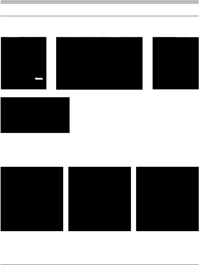
2. RACK ROLLERS - Upper & Lower
Fig. 2-1 |
Fig. 2-2 |
Fig. 2-3 |
•The Upper Rack can be removed by releasing the Rail Clip and sliding the Rack out from the Rail (Fig. 2-1). If the Upper Rack Roller Assembly must be replaced (Fig 4-2) first remove the Side Panel (see Section 22) and then remove the four (4) 8mm bolts that mount the Roller Assembly to the Tank.
•Once the Upper Rack has been removed, the Rack Roller Wheels can be replaced by gently prying the Hub Clips inward with a small screwdriver and
Fig. 4-4 |
then moving the Roller Wheel out and off the Hub (Fig. 2-3). |
|
•The Lower Rack Roller Assemblies are held in place using three (3) tension clips (Fig 2-4). Grasping the Roller Assembly and applying downward force will disengage the Roller Assembly from the Rack.
3. UPPER SPRAY ARM
Fig. 3-1 |
Fig. 3-2 |
Fig. 3-3 |
•To remove the Upper Spray Arm (Fig. 3-1) gently grasp the Locking Ring with a Channel Locks and turn Counter-Clockwise (Fig. 3-2); note the Tab and Slot locking configuration (Fig. 3-3).
TECH NOTE: When Replacing the Spray Arm make sure that it is tightened completely onto the Locking Ring.
Page: 2

REPAIR MANUAL
L 63 / LL 64 / LL 65 LI 640 / LI 670 / LI 700
4. LOWER SPRAY ARM
Fig. 4-1
Fig. 4-2 |
Fig. 4-3 |
•To remove the Lower Spray Arm (Fig. 4-1) hold the Spray Arm Locking Ring with a Channel Locks and then turn the Spray Arm Clockwise (Fig. 4-2). The Locking Ring Assembly can also be removed by rotating it Counter-Clockwise; note the Tab and Slot locking configuration (Fig. 4-3).
TECH NOTE: When Replacing the Spray Arm make sure that it is tightened completely onto the Locking Ring.
Page: 3

REPAIR MANUAL
L 63 / LL 64 / LL 65 LI 640 / LI 670 / LI 700
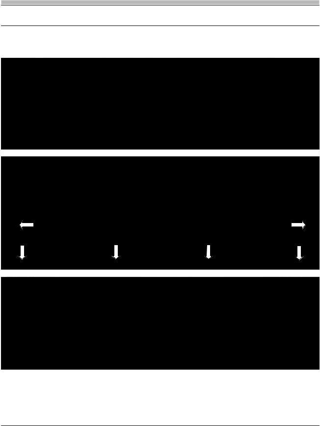
5. OUTER DOOR PANEL
 A A
A A B
B
 B B
B B
Fig. 5-1
•The Outer Door is held in place using four (4) Phillips screws (Fig. 5-1). Screw “A” is a single screw located on the bottom left and right corners of the Inner Door Panel. Screw “B” is just below the Phillips screw that holds the Outer Door Skin (Fig. 5-2).
•With the four (4) screws removed raise the Door to an upright position and then slide the Outer Door Panel down and out from the Alignment Channel (Fig. 5-3).
•When replacing the Outer Door insert the Alignment Pin into the Channel and then raise the Door Panel up until it is even with the top of the Control Panel (Fig. 5-4).
TECH NOTE: To prevent damage to the Outer Door, Alignment Pins, or Channel, make sure to support the weight of the Door as you remove or replace it.
Fig. 5-2
Fig. 5-3
Fig. 5-4
Page: 4
REPAIR MANUAL
L 63 / LL 64 / LL 65 LI 640 / LI 670 / LI 700
6. CONTROL PANEL
Fig. 6-1
Fig. 6-2
Fig. 6-3
•To remove the Control Panel (Fig. 6-1), remove the six (6) Phillips Control Panel screws from the Inner Door Panel (Fig 6-2). With the screws removed the Control Panel will lay forward and is now accessible for repair (Fig. 6-3).
TECH NOTE: The Outer Door must be removed first (see Section 5) before removing the Control Panel Screws.
Page: 5
 Loading...