

Aprilia Ditech 50 AC 2002 Owner's manual
aprilia
QUICK WORKSHOP
HANDBOOK
Electronic air injection
Aprilia Ditech Engine
1095 2
General safety
norms
Technical data
Oil chart
Special engine tools
Injection troubleshooting
Disassembly/Reassembly
sequence
1
2
3
44
5
6
Air-injection 50 cc
INTRODUCTIONCONTENTS
- This manual contains all the essential information for
carrying out routine vehicle procedures.
- The information and diagrams in the manual are upto-date at the time of publication.
- This publication is intended for use by Aprilia dealers
and their trained mechanics. A large number of
procedures do not require explanation and therefore
have been omitted. It has not been possible to give
detailed mechanical data for every procedure. All personnel consulting this manual must therefore possess
the basis skills of a mechanic and be thoroughly familiar
with the most common motor cycle repair procedures.
Without these skills and the necessary familiarity any
repair or routine maintenance operation may be
ineffective or even dangerous.
Given the fact that it is not possible to provide detailed
descriptions of all procedures, special care must be
taken for whatever repair or maintenance work is done,
in order to prevent damage to the vehicle and injury to
persons.
In order to provide the best level of customer
satisfaction, Aprilia s.p.a. constantly improves its
products and relevant documentation. All important
technical changes and alterations to procedures are
notified to all Aprilia dealers, branches and points of
sale throughout the world. All changes will be included
in later editions of this manual.
If you have any doubts or queries about the procedures
described in this manual, please contact the Aprilia
Training and Documentation Department, who will be
pleased to give you all the information and explanations
you require, and to bring you up-to-date with any
changes.
For further information see:
- SPARE PARTS CATALOGUE no. 5601
Produced by
Training and Documentation Department
aprilia s.p.a.
Via G. Galilei, 15 - 30033 Noale (VE) - Italy
Tel. +39 - 041 55829111
Fax + 39 - 041 441054
www.aprilia.com
Produced and printed by
Studio Gallo Design srl
Via Mogno,34/1
35012 Camposampiero (PD)
tel. 049 - 9303475
fax. 049 - 9317954
Italy
www.stgallo.it
e-mail: design@stgallo.it
Release 00 / 2002 - 09
Without alteration to the basic features of its models
as described and illustrated in this manual, Aprilia
s.p.a. may carry out modifications to any of the models
without notice.
Unauthorized electronic retrieval or reproduction of any
part of this manual is unlawful in all countries. Products
or services manufactured or provided by third parties
are quoted merely as examples and do not constitute
a recommendation; Aprilia s.p.a. is not liable for the
performance or use of such products and services.
First edition. September 2002.
01 / 01Chapter.1
Air-injection 50 cc
GENERAL SAFETY NORMS
CARBON MONOXIDE
If the engine must be switched on to carry out certain
operations make sure the room is well ventilated or
open to the outside. Never switch on the engine in a
closed room, unless there is a smoke and fume removal
system installed
and the operating.
DANGER
Exhaust fumes contain carbon monoxide, a
poisonous gas which make cause loss of
consciousness and can be lethal.
Switch on the engine only in an open space or in a
closed room if fitted with a fully operating smoke and
fume removal system.
FUEL
Make sure the room is well ventilated. Extinguish all
cigarettes, keep fuel containers away from flames and
possible sources of sparks.
DANGER
Fuel is highly flammable and may explode.
Take special care to check the air and fuel injection
plant hoses; the operating pressure should not
exceed about 750 KPa (7.5 bar).
Any fuel hoses which are cut or cracked should be
replaced.
KEEP OUT OF THE REACH OF CHILDREN
HIGH TEMPERATURE COMPONENTS
DANGER
The engine and parts of the exhaust system reach
very high temperatures and remain hot for a certain
period after switching off the engine. Handle these
components only after putting on protective gloves
or waiting for the engine and parts to fully cool
down.
WASTE TRANSMISSION OIL
DANGER
Use latex gloves for maintenance operations
involving contact with oil. If left in contact with the
skin for long periods, used engine oil can cause
skin cancer. Although this is unlikely, unless
handled every day, wash your hands with soap and
water after handling used engine oil.
KEEP OUT OF THE REACH OF CHILDREN
GENERAL PRECAUTIONS AND INFORMATION
For repair and disassembly and reassembly operations
follow the instructions.
DANGER
Do not carry out any operation in the presence of
naked flames.
Before starting any maintenance or inspection
operation, switch off the engine and remove the
ignition key. Wait for the engine and exhaust
system to cool down. Place the motor cycle, if
possible, in a raised position on a level, even
surface. Take special care of heated parts (engine
and the exhaust) in order to avoid burns.
The vehicle is made with parts which cannot be
swallowed. Do not bite, chew, suck or otherwise
attempt to carry out operations using the teeth or
mouth.
Unless otherwise specified, to reassemble parts,
reverse the order for disassembly operations.
Some operations may involve disassembling parts
previously disassembled for other operations to
be carried out. Consult the various pages of the
manual where each operation is described in order
to avoid unnecessary work. Never use fuel as a
solvent for cleaning the vehicle.
If welding operations are to be carried out,
disconnect the negative pole (-) of the battery and
take special care with all electrical components
used for the injection system.
If more than one person is working on the vehicle
make sure both are in a safe position whatever the
work being done.
Release 00 / 2002 - 09
Chapter.1
01 / 02

Air-injection 50 cc
BEFORE DISASSEMBLY
- Remove dirt, mud, dust and foreign bodies from the
vehicle before disassembling the components.
- Use all the tools specifically designed for the vehicle.
DISASSEMBLY
- Before separating pipes or wires etc. (joints and
junctions) mark each part with a unique marking.
Each piece should be clearly marked for reassembly
purposes.
-Clean and wash the disassembled components with
close to non-inflammable detergent.
-Keep paired parts together, because normal wear and
tear create a natural pairing. In some cases, where
one part is replaced the other must also be replaced.
Keep away from sources of heat.
REASSEMBLY
DANGER
Never re-use a snap ring. If removed, replace it with
a new ring. If a new ring is fitted, do not stretch
more than necessary when fitting it to the shaft.
Afterwards, check that the ring is properly fitted to
the housing.
- Lightly smear the edges of oil seals with lithium based
grease.
- Refit the oil seals and bearings with the trademark or
manufacturer’s serial number facing outwards (so it
is visible).
- Grease the bearings fully before fitting.
- Check that all components have been reassembled
properly.
After a maintenance or repair operation, carry out
preliminary checks and commission the vehicle on
private property or in a low traffic area.
Do not clean bearings with compressed air.
IMPORTANT Bearings must rotate freely, without
sticking or noise. Replace if necessary.
- Use only ORIGINAL Aprilia SPARE PARTS.
- Stick to the oil chart and recommended wearing parts.
- Wherever possible, lubricate parts before
reassembling them.
- When tightening screws and nuts begin with the
largest diameters, or inner nuts and screws, and
tighten diagonally. Tighten each before finally
tightening to the specified torque.
- Always replace gaskets, gasket rings, snap rings, Orings and split pins with new ones.
- Clean all joint surfaces, oil seal edges and gaskets
before reassembling.
Release 00 / 2002 - 09
01 / 03Chapter.1

ENGINE
Air-injection 50 cc
TECHNICAL DATA
Type
Engine type
Number of valves
Number of cylinders
Piston displacement
Bore/Stroke
Corrected compression ratio
Idle rpm
Starter system
Clutch
Gearbox
Lubrication system
Cooling system
TRANSMISSION
Variator
Primary
Gears
Secondary
CAPACITY
air/injection
air-injection with direct petrol injection
-
mono-cylindrical horizontal
49.38 cm
41.0 mm / 37.4 mm
rc = 10.7 ± 0.1
1650 ± 50 r/min
electric
centrifuge
automatic stepless variator
Electric oil pump
forced air
automatic stepless
V- belt
minimum for stepless change: 2.9
maximum for stepless change: 0.75
with gears
3
Transmission oil
THROTTLE BODY
Type
Diffuser
FUEL SUPPLY
Fuel injector
Air injector
IGNITION UNIT
Type of ignition
Ign advance
SPARK PLUG
Standard
Electrode-spark plug distance
ELECTRICAL INSTALLATION
Battery
Fuse
Generator (magneto)
130 cm
Ø18 mm
SIEMENS DEKA
SYNERJECT
Inductive
Variable: 20° at 3000 rpm 17° at 7500 rpm.
NGK R CPR8-E
0.55 - 0.65 mm
12 V - 4 Ah
12 V - 140 W
3
BING
7.5 A
Release 00 / 2002 - 09
02 / 01Chapter.2
Air-injection 50 cc
TIGHTENING TORQUE 50 cc AIR INJECTION ENGINE
Application
Pick-up locking
Stator locking
Transmission steel plate locking
Throttle body (with roller) hose clamp locking
Suction manifold (built-in, hexagonal) locking
Screws and pin securing intake manifold
Transmission cover
Variator cover
Bendix support locking
Starter motor
L/r carter locking
Wheel bearing retaining plate locking
Oil load plug (flanged)
Oil unload (Ch. 8)
Variator sliding pulley cover locking
Head locking (nut)
Clutch locking (nut)
Flywheel locking (nut)
Exhaust stud
Cylinder stud
Spark plug (thread)
Compressor screw locking
Fuel rail screw locking (flanged TE)
Variator fixed pulley locking (nut)
Cylinder head temperature probe
Screw
M5 x 12
M5 x 25
M6 x 12
M6 x 20
M6 x 25
M6 x 25
M6 x 30
M6 x 25
M6 x 55
M6 x 75
M6 x 100
M6 x 16
M8 x 12
M6 x 12
M4 x 8
M6 h=9
M10x1.5
M10x1.25
M10x1.0
M5 x 20
M5 x 25
M12x1.25
6 - 9
TIGHTENING
TORQUE
Nm
4 - 6
4 - 6
8 - 12
end stop
8 - 12
9 - 11
8 - 12
8 - 12
8 - 12
8 - 12
8 - 12
6 - 10
10 - 14
5 - 6
2
11 - 13
45 - 55
35 - 45
4 - 5
4 - 5
13 - 15
4 - 5
6 - 7
35 - 45
6 - 9
Kgm
0.4 - 0.6
0.4 - 0.6
0.8 - 1.2
end stop
0.8 - 1.2
0.9 - 1.1
0.8 - 1.2
0.8 - 1.2
0.8 - 1.2
0.8 - 1.2
0.8 - 1.2
0.6 - 1.0
1.0 - 1.4
0.5 - 0.6
0.2
1.1 - 1.3
4.5 - 5.5
3.5 - 4.5
0.4 - 0.5
0.4 - 0.5
1.3 - 1.5
0.4 - 0.5
0.6 - 0.7
3.5 - 4.5
0.6 - 0.9
Sealant
not
not
Loctite 270
not
not
not
not
not
not
not
not
Loctite 243
not
not
not
not
not
not
Loctite 270
not
/
not
not
not
Release 00 / 2002 - 09
02/ 02Chapter.2

TECHNICAL DATA
CYLINDER + PISTON + RINGS
Air-injection 50 cc
Item:
Piston to cylinder
clearance
Piston diam.
Cylinder bore
Air-
injection
Air-
injection
Air-
injection
Standard: mm (in)
0.028-0.040
(0.0011-0.0016)
Selection A 40.966-40.972
(*) (1.6128-1.6131)
Selection B 40.972-40.978
(*) (1.6131-1.6133)
Selection C 40.978-40.984
(*) (1.6133-1.6135)
Measure 18 mm (0.7) from
the outer edge
Selection A 41.000-41.006
(1.6141-1.6144)
Selection B 41.006-41.012
(1.6144-1.6146)
Selection C 41.012-41.018
(1.6146-1.6149)
Limit: mm
(in)
0.100
(0.0039)
40.912
(1.6107)
40.918
(1.6109)
40.924
(1.6112)
41.050
(1.6161)
41.056
(1.6164)
41.066
(1.6168)
Measure 15 mm (0.59) from
the outer edge
Cylinder distortion
Cylinder head distortion
0.005
(0.0002)
0.02
(0.0008)
0.03
(0.0012)
0.05
(0.0020)
(*) N.B. During disassembly selections A,B, C may not be visible. In this case, refer to limit
values.
Release 00 / 2002 - 09
02 / 03Chapter.2
CYLINDER + PISTON + RINGS
Air-injection 50 cc
Item:
Port at the end of the unassembled
segment
Port at the end of the segment fitted
into the cylinder
Segment/slot clearance
Piston pin housing bore on piston
Air-
injection
Air-
injection
Air-
injection
Air-
injection
1°-2°
1°-2°
1°-2°
Standard:
mm (in)
T Approx.
T
12.002 - 12.010
(0.4725 - 0.4728)
0.25 - 0.40
(0.0098 - 0.0157)
0.036 - 0.076
(0.0014 - 0.0030)
4.5
(0.18)
Limit:
mm (in)
3.6
(0.14)
0.70
(0.027)
-
-
12.030
(0.4736)
Piston pin outer diameter
Air-
injection
11.996 - 12.000
(0.4723 - 0.4724)
11.980
(0.4717)
Release 00 / 2002 - 09
02 / 04Chapter.2
CONROD + CRANKSHAFT
Air-injection 50 cc
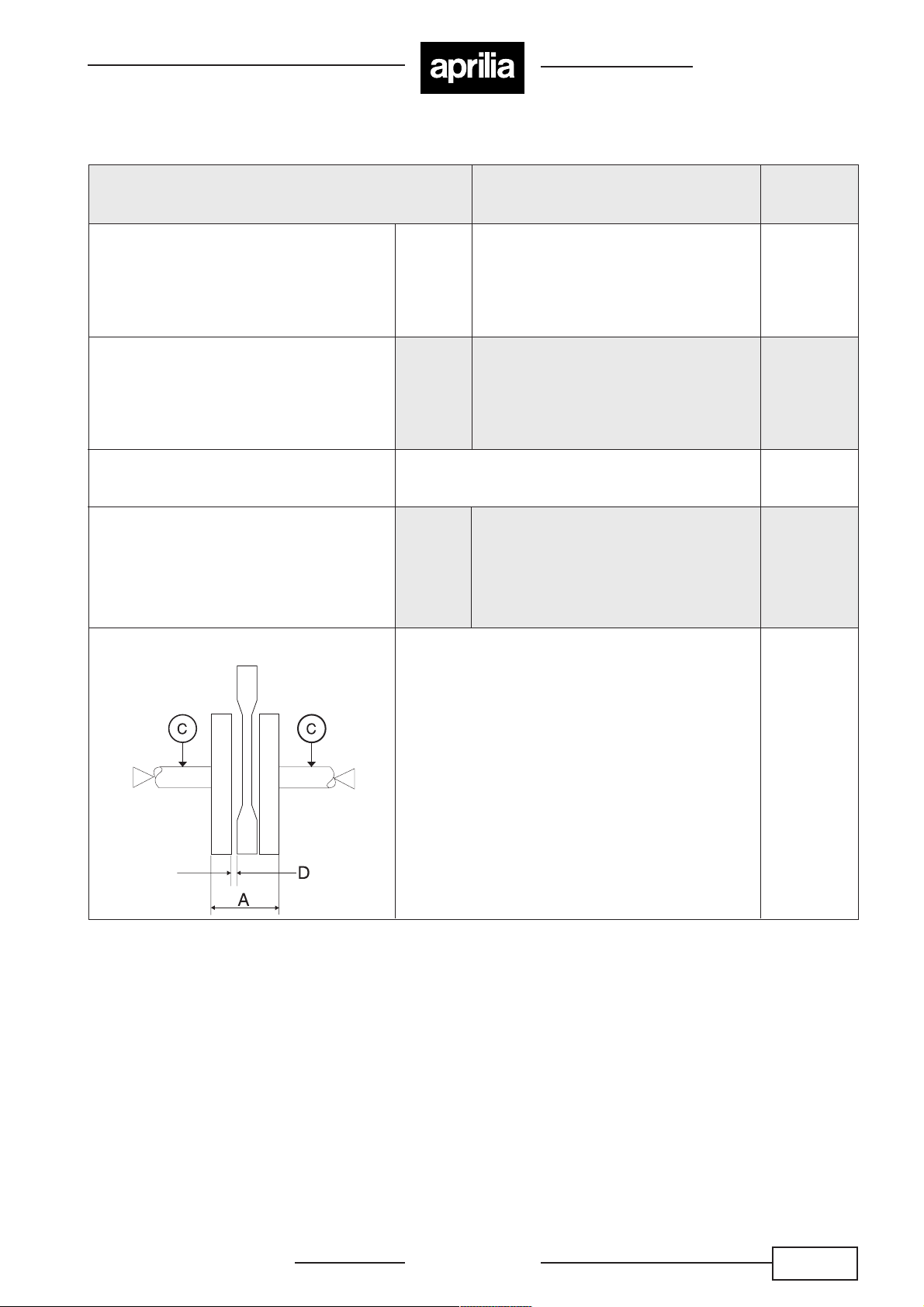
Item:
Connecting rod small end diameter
Width from crank arm to arm (A)
Misalignment limit (C)
Side clearance of connecting rod big
end (D)
Standard:
mm (in)
Air-
injection
Air-
injection
Measured between two opposite points
Air-
injection
(0.6300 - 0.6304) 36.0 ± 0.05
16.003 - 16.011
37.95 - 38.10
(1.494 - 1.5)
0.15 - 0.75
(0.0059 - 0.029)
Limite:
mm (in)
16.040
(0.6315)
-
-
0.03
(0.001)
-
Standard crank width
Release 00 / 2002 - 09
02 / 05Chapter.2
CLUTCH
Air-injection 50 cc
Item:
Clutch wheel inner diameter
Clutch shoe thickness
Clutch engagement
Clutch lock-up
OIL PUMP
Item:
Inner coil
TRANSMISSION
Standard: mm (in)
110.00 - 110.15
(4.331 - 4.337)
3.0
(0.12)
3200 ± 200 rpm
6700 ± 300 rpm
Specification:
Ri = 26.3 ± 2.6 Ω a 20° C
Limit:mm (in)
110.50
(4.350)
2.0
(0.08)
-
-
Item:
Reduction ratio
Final reduction ratio
Drive belt width
Driven face spring free
Guide roller for variator
Drum diameter
Air-
injection
Air-
injection
Standard: mm (in)
Variable 2.9 - 0.75
51/15 x 67 x 14
18.4 (0.724)
110 (4.33)
17 (0.669)
107 - 107.2
(4.213 - 4.220)
Limit: mm (in)
-
-
17.4 (0.685)
104.5 (4.114)
16.5 (0.650)
107.5
(4.232)
Release 00 / 2002 - 09
02 / 06Chapter.2
 Loading...