


95014-2084

Apple
Video System
User’s Manual

K Apple Computer, Inc.
© 1996 Apple Computer, Inc. All rights reserved.
Under the copyright laws, this manual may not be copied, in whole or in part, without
the written consent of Apple. Your rights to the software are governed by the
accompanying software license agreement.
The Apple logo is a trademark of Apple Computer, Inc., registered in the U.S. and
other countries. Use of the “keyboard” Apple logo (Option-Shift-K) for commercial
purposes without the prior written consent of Apple may constitute trademark
infringement and unfair competition in violation of federal and state laws.
Every effort has been made to ensure that the information in this manual is accurate.
Apple is not responsible for printing or clerical errors.
Apple Computer, Inc.
1 Infinite Loop
Cupertino, CA 95014-2084
(408) 996-1010
Apple, the Apple logo, LaserWriter, Macintosh, and QuickTime are trademarks of Apple
Computer, Inc., registered in the U.S. and other countries.
Adobe, Adobe Illustrator, Adobe Photoshop, and PostScript are trademarks of Adobe
Systems Incorporated, and/or its subsidiaries and may be registered in certain
jurisdictions.
Helvetica is a registered trademark of Linotype-Hell AG and/or its subsidiaries.
Simultaneously published in the United States and Canada.
Mention of third-party products is for informational purposes only and constitutes
neither an endorsement nor a recommendation. Apple assumes no responsibility with
regard to the performance or use of these products.
The Apple Publishing System
This Apple manual was written, edited, and produced on a desktop publishing system
using Apple Macintosh computers and QuarkXPress. Technical illustrations were
drawn in Adobe
™
Illustrator; screen shots were created and modified with system
software, ExposurePro, and Adobe Photoshop. Final pages were output using
PostScript
™
technology.
Text type is Apple Garamond, Apple’s corporate font. Display type is Helvetica
®
Black.
Ornaments are custom symbols designed for Apple Computer.
PostScript, the LaserWriter page-description language, was developed by Adobe
Systems Incorporated.
ii

iii
CONTENTS
Communications regulation information iv
Preface vii
1 Installing the Card and Software and
Connecting Video Equipment 1
What you should have 2
Installing the video input card 2
Installing the software 41
Connecting video equipment 43
2 Learning About the Software 51
Opening the Apple Video Player 52
Getting help 53
Choosing the correct video source 54
Adjusting the sound 56
Adjusting the picture 58
Changing the video window size 59
Changing the window color 60
Setting the video input standard 61
Setting and using a “hot key” 62
3 Capturing Video Images 63
Capturing individual images 64
Capturing movies 66
4 Troubleshooting 71
5 Technical Information 77
Index 79

Communications regulation information
FCC statement
This equipment has been tested and found to comply with the limits for a Class B
digital device in accordance with the specifications in Part 15 of FCC rules. See
instructions if interference to radio or television reception is suspected.
Radio and television interference
The equipment described in this manual generates, uses, and can radiate radio-
frequency energy. If it is not installed and used properly—that is, in strict accordance
with Apple’s instructions—it may cause interference with radio and television
reception.
This equipment has been tested and found to comply with the limits for a Class B
digital device in accordance with the specifications in Part 15 of FCC rules. These
specifications are designed to provide reasonable protection against such interference
in a residential installation. However, there is no guarantee that interference will not
occur in a particular installation.
You can determine whether your computer system is causing interference by turning it
off. If the interference stops, it was probably caused by the computer or one of the
peripheral devices.
If your computer system does cause interference to radio or television reception, try to
correct the interference by using one or more of the following measures:
m Turn the television or radio antenna until the interference stops.
m Move the computer to one side or the other of the television or radio.
m Move the computer farther away from the television or radio.
m Plug the computer into an outlet that is on a different circuit from the television or
radio. (That is, make certain the computer and the television or radio are on circuits
controlled by different circuit breakers or fuses.)
If necessary, consult an Apple-authorized service provider or Apple. See the service and
support information that came with your Apple product. Or, consult an experienced
radio/television technician for additional suggestions.
Important Changes or modifications to this product not authorized by Apple
Computer, Inc., could void the FCC Certification and negate your authority to operate
the product.
iv
This product was tested for FCC compliance under conditions that included the use of
Apple peripheral devices and Apple shielded cables and connectors between system
components. It is important that you use Apple peripheral devices and shielded cables
and connectors between system components to reduce the possibility of causing
interference to radios, television sets, and other electronic devices. You can obtain
Apple peripheral devices and the proper shielded cables and connectors through an
Apple-authorized dealer. For non-Apple peripheral devices, contact the manufacturer
or dealer for assistance.
DOC statement
DOC Class B Compliance This digital apparatus does not exceed the Class B limits
for radio noise emissions from digital apparatus as set out in the interference-causing
equipment standard entitled “Digital Apparatus,” ICES-003 of the Department of
Communications.
Observation des normes—Classe B Cet appareil numérique respecte les limites de
bruits radioélectriques applicables aux appareils numériques de Classe B prescrites
dans la norme sur le matériel brouilleur : “Appareils Numériques”, NMB-003 édictée
par le ministre des Communications.
VCCI statement
v

PREFACE
This manual tells you how to install and use the video input
card and software, and connect video equipment, so that
you can
m view video from a variety of sources in a window that you
can move or resize
m adjust the color and sound
m capture a single image or a series of images on disk
vii

This chapter covers installing the video input card and
software. It also shows how to connect video equipment to
the card.
If you purchased your computer with the video input card
already installed, go to the section “Connecting Video
Equipment,” later in this chapter.
1
CHAPTER
1
Installing the Card
and Software and Connecting
Video Equipment
What you should have
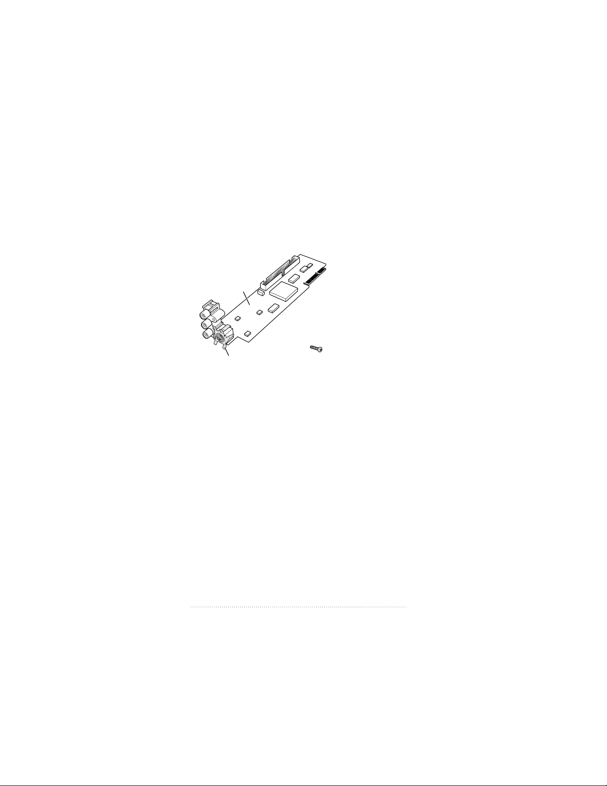
Check your package to make sure you have both the
video input card and an attachment screw. Your package
also contains floppy disks from which you will install the
software later.
Note: The grounding clip may be a separate piece in your
package. If so, you will attach it by following instructions
later in the manual.
Installing the video input card
You install the video input card by attaching the card to the
computer and then connecting the card to your video
equipment. The steps for attaching the card to the computer
vary slightly depending on whether or not the computer has
a built-in monitor.
Installing the card in a compact computer
If your system has a built-in monitor, continue with the steps
in this section. Otherwise, go to the section that follows,
“Installing the Card in a Modular Computer.”
Grounding clip
Video input card
Attachment screw
2
Chapter 1
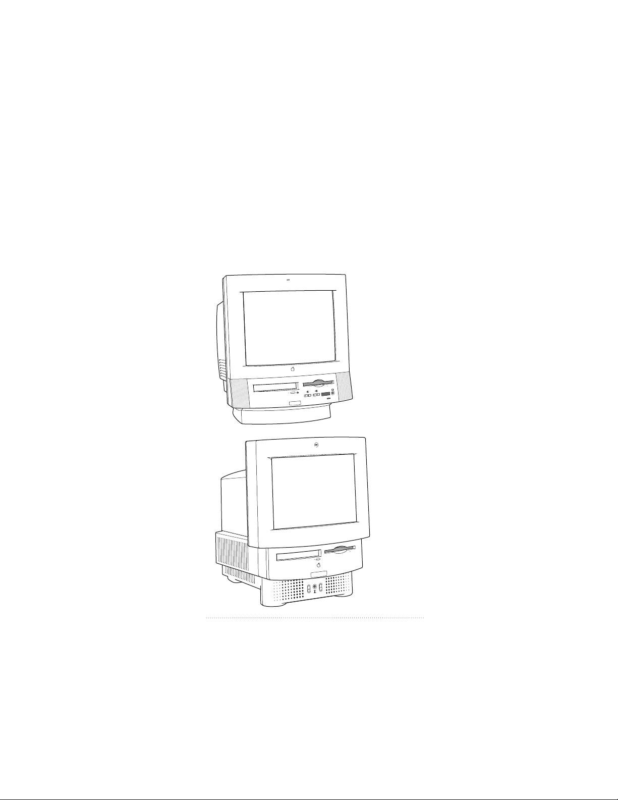
Your compact computer may look like either of the
computers pictured below; the steps for installing the
card vary slightly depending on which model you have. If
your computer looks like Style A, follow the first set of steps
to install the video input card. If your system looks like
Style B, skip to the second set of steps, “Installing the Card
in Style B.”
Style B
Style A
3
Installing the Card and Software and Connecting Video Equipment

Installing the card in Style A
1 Make sure you save any open documents and quit any open
applications. Then turn off the computer.
m Choose Shut Down from the Special menu, or press the
Power key on the keyboard.
m Then press the power switch at the back of the computer.
Press the side of the switch marked with the j symbol.
2 Unplug all the cables except the power cord from your
computer.
Leaving the power cord plugged in helps protect the
computer from electrostatic discharge damage.
Important To avoid generating static electricity that may
damage components, do not walk around the room until you
have finished installing the card and closed the computer.
Additionally, move the logic board as little as possible while it
is outside the computer.
4
Chapter 1
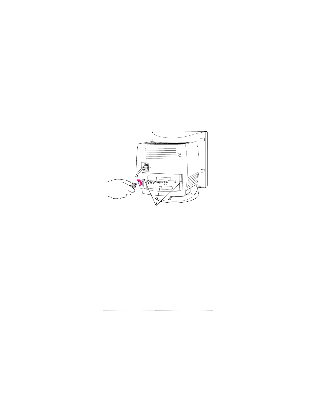
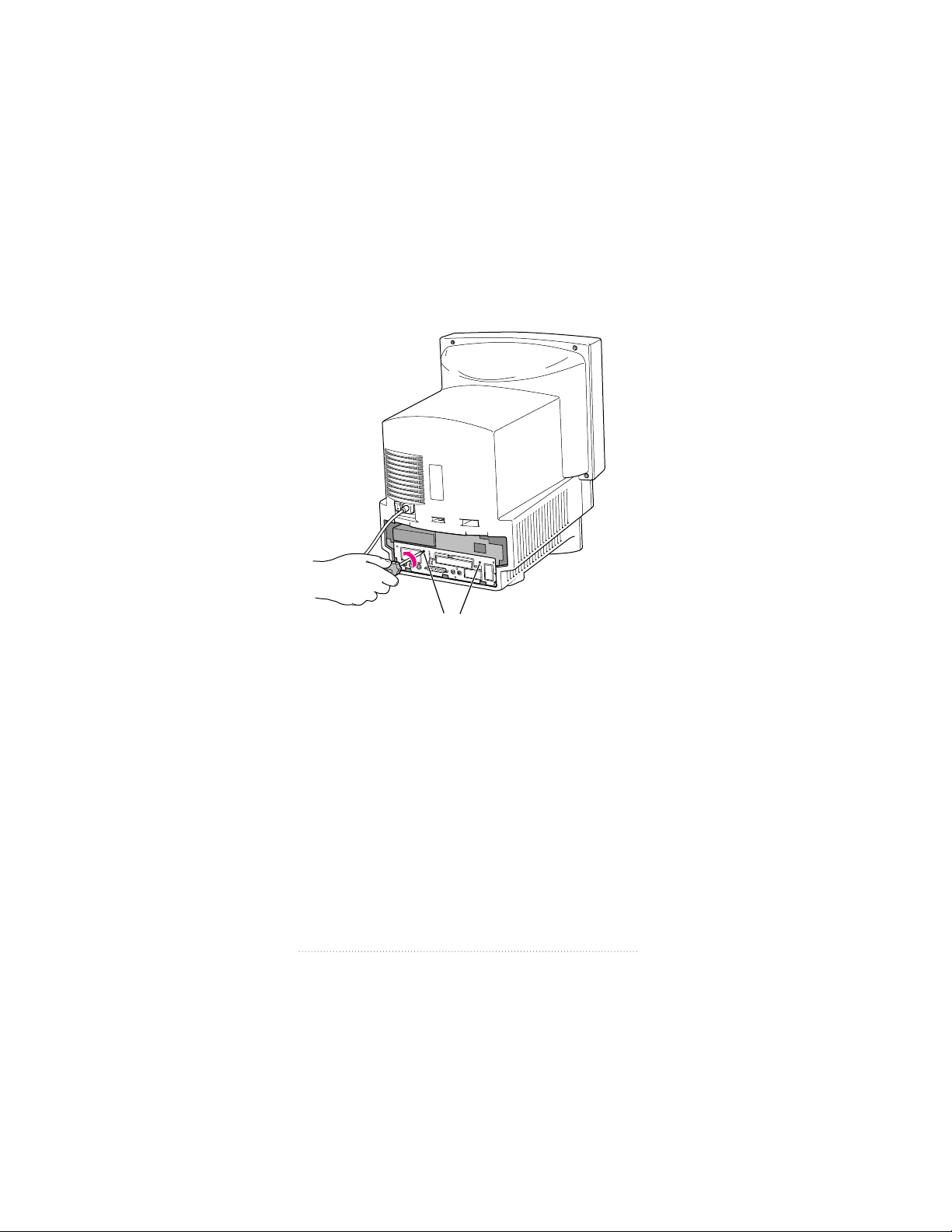
3 Use a screwdriver to remove the screws from the back panel.
Note: Your computer may have only two screws (on either
side of the back panel) to remove. Even if the back of your
computer looks different, all the ports should be in the same
location as pictured here.
Remove these screws.
(Your computer may have only two screws.)
5
Installing the Card and Software and Connecting Video Equipment
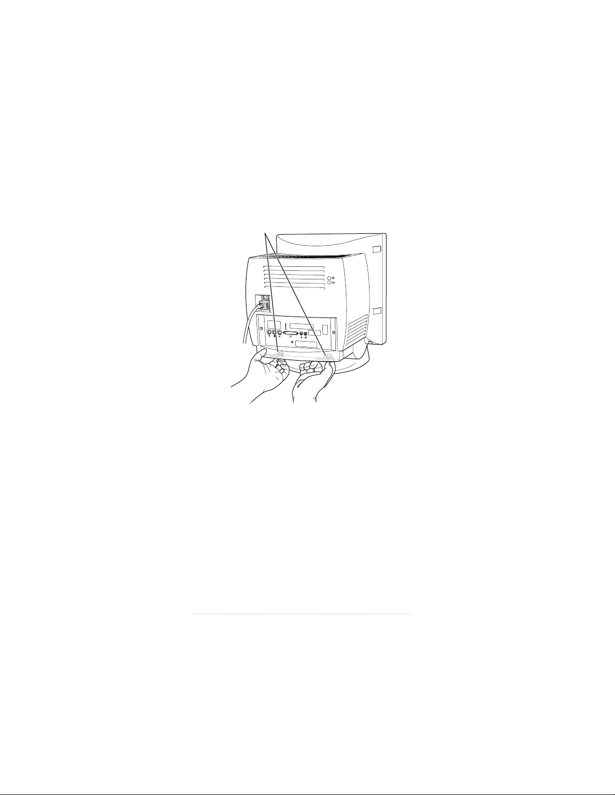
4 With your fingertips, locate the two latches on the underside
of the computer’s case.
With your fingertips, locate the two latches on the underside
of the computer’s case.
6
Chapter 1
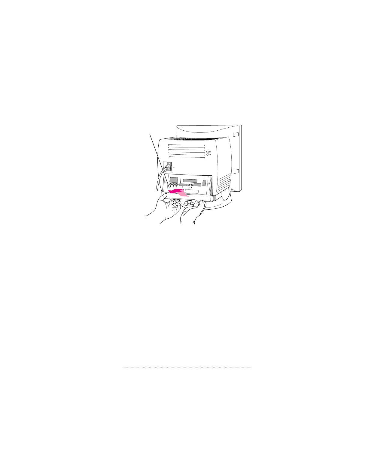
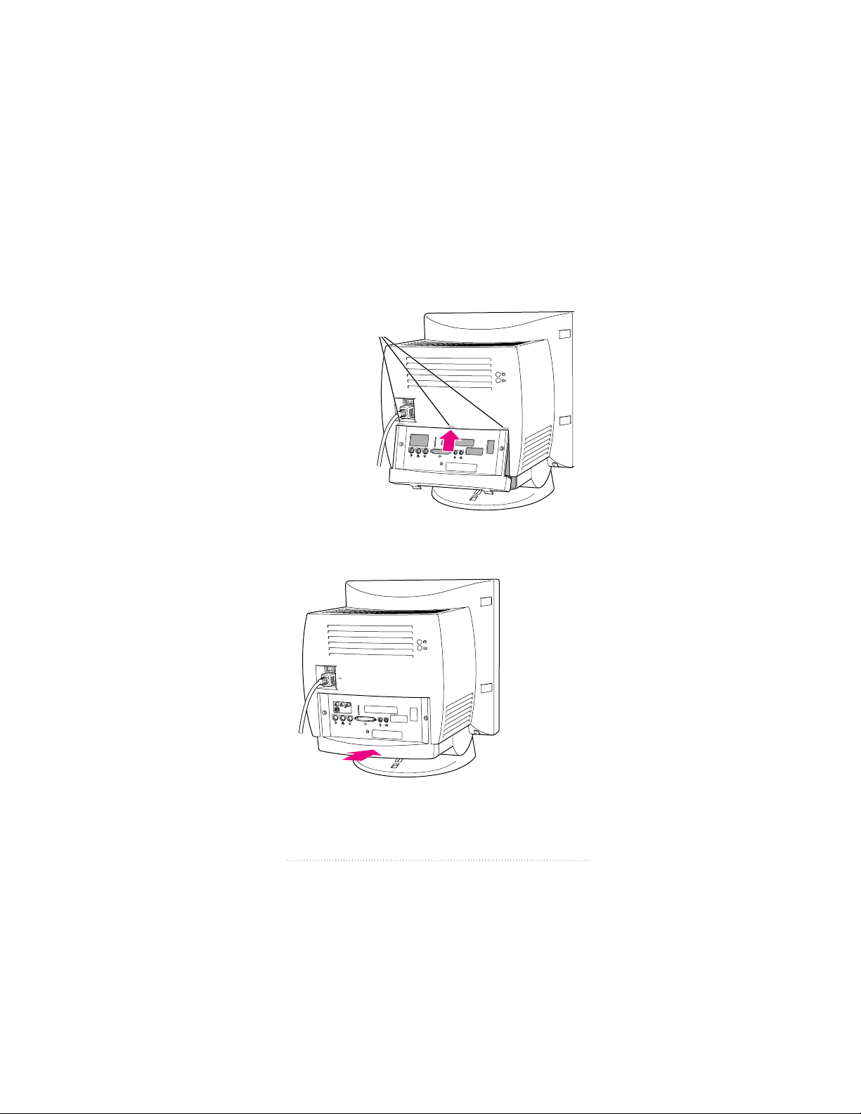
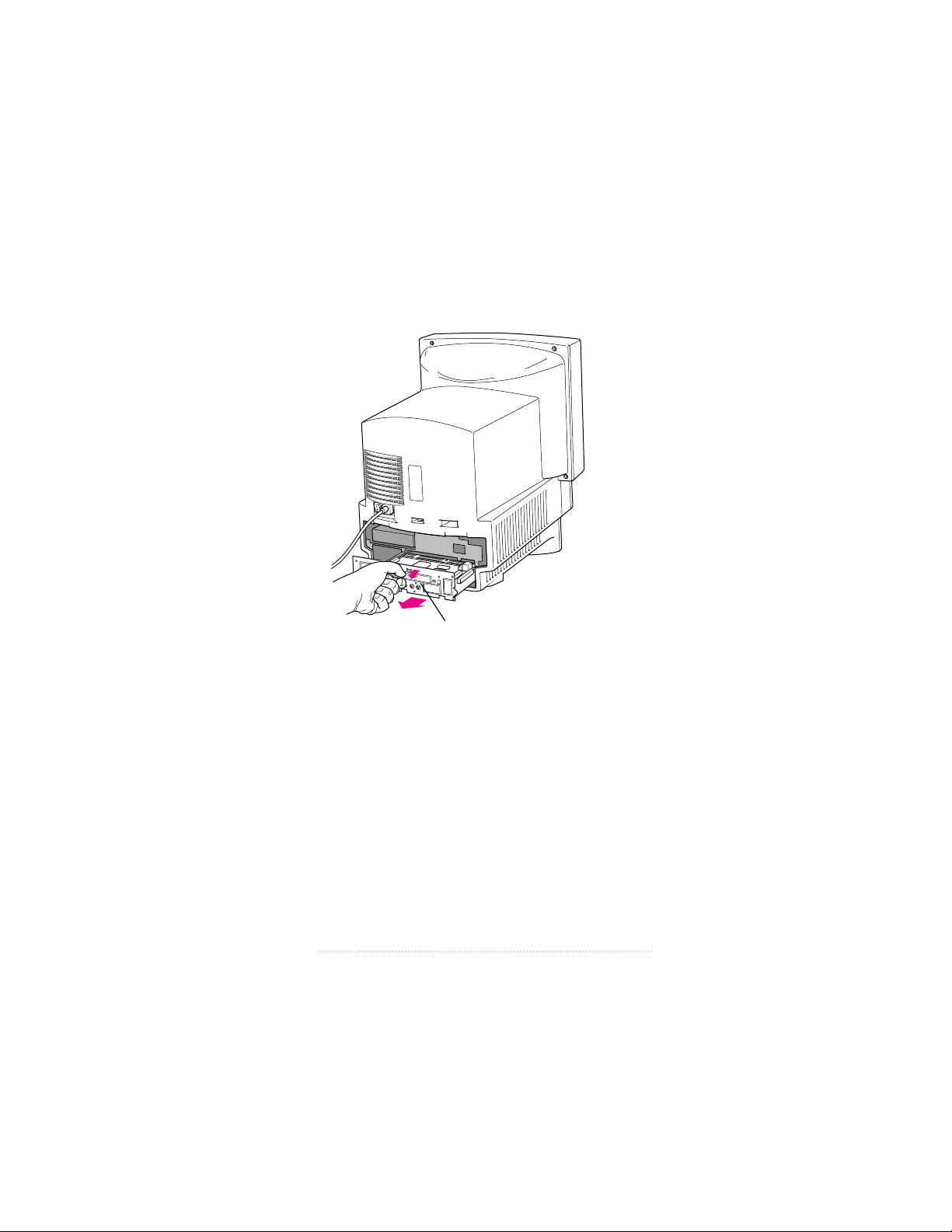
5 Pulling gently, swing the panel up and slip it out.
Remember: Don’t walk around the room until you have
finished installing the card and closed the computer. Move
the logic board as little as possible while it’s outside the
computer.
Pulling gently, swing the
panel up and slip it out.
7
Installing the Card and Software and Connecting Video Equipment

6 There is a wire handle on the back of the logic board. Swing
it down and use it to pull the logic board toward you.
The logic board is plugged into a slot inside the computer.
You may have to brace the computer with your other hand
and pull firmly at first. Slide the entire logic board all the way
out of the computer.
Wire handle
8
Chapter 1
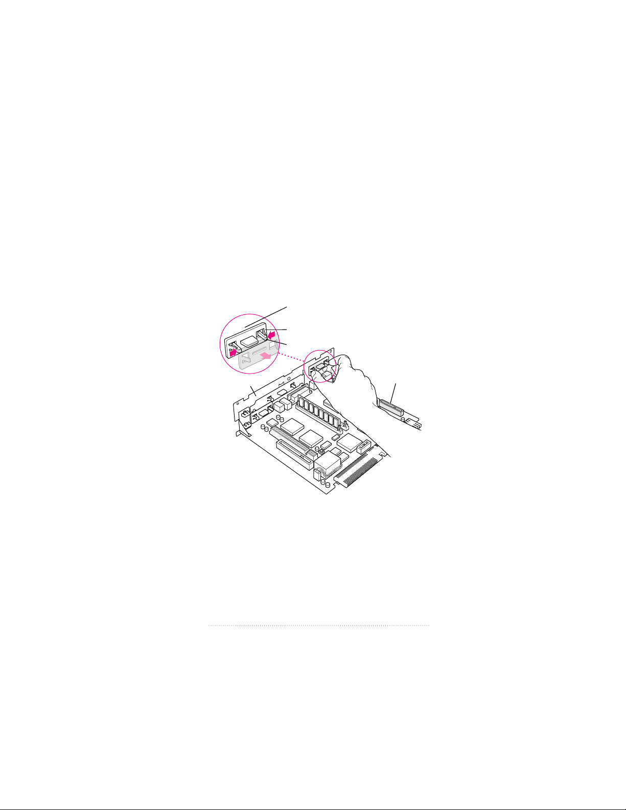
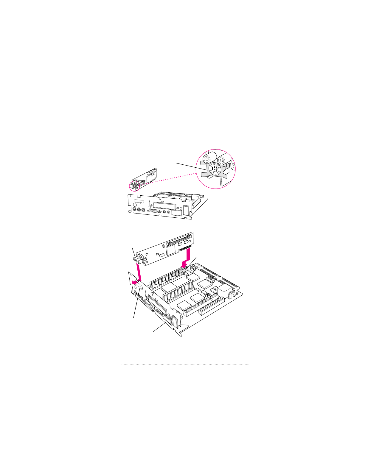
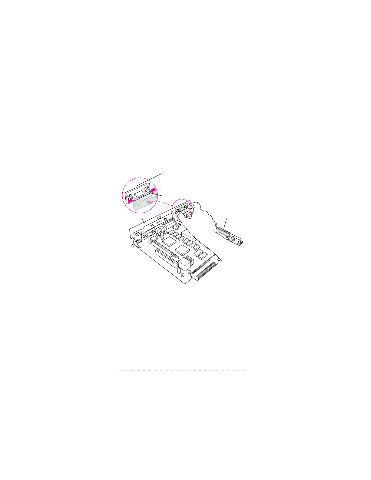
7 Locate the video-in access cover on one side of the vertical
plate attached to the logic board. Remove the cover from
this opening by squeezing together the plastic tabs that hold
it in place.
Note: Your logic board may not look exactly like the one
pictured here, but the video-in slot and plastic access
cover are in the same position regardless of the logic board
you have.
Video-in slot
Vertical plate
Plastic tabs
The plastic access cover is on the
other side of the vertical plate.
Metal retainer
9
Installing the Card and Software and Connecting Video Equipment
8 Remove the video input card from its static-proof bag.
Handle the card by its edges in order to avoid touching the
connectors.
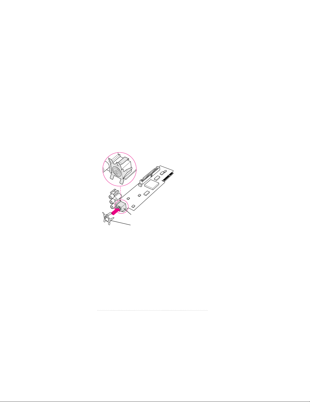
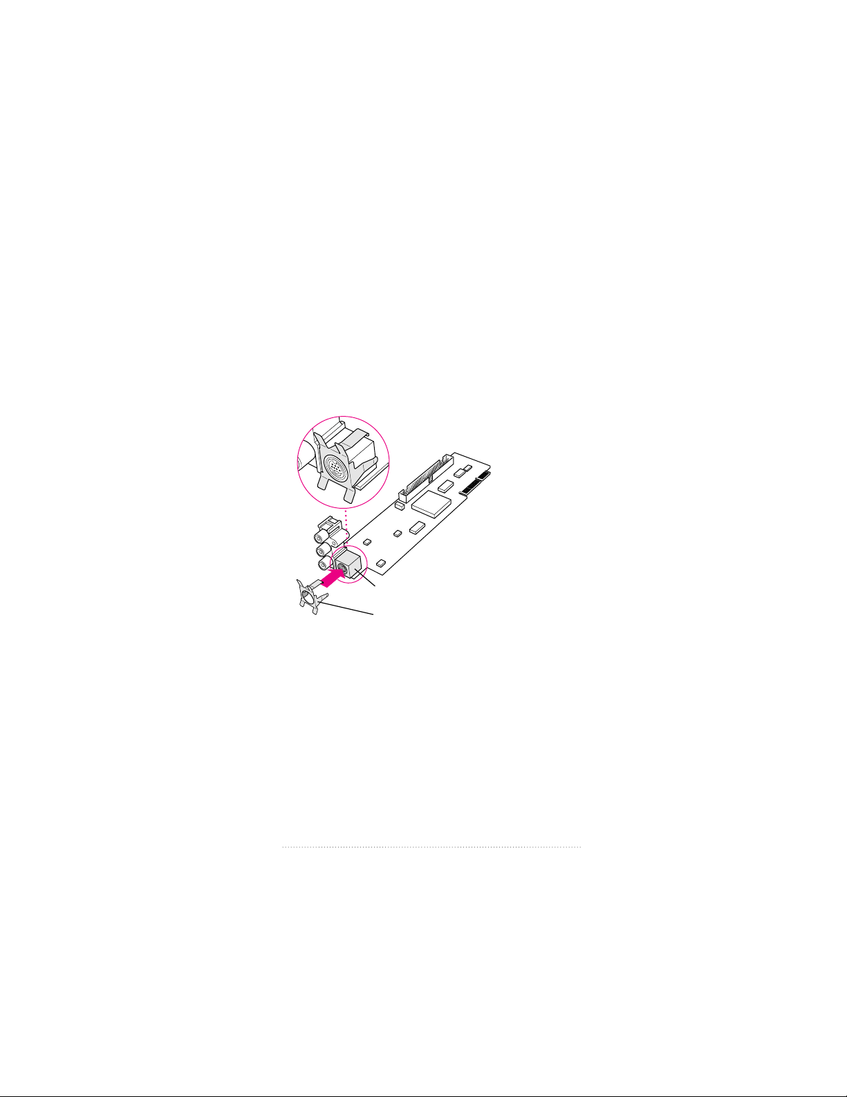
9 Attach the grounding clip to the S-video port of the video
input card, if it isn’t attached already.
Important Without the grounding clip attached, the
S-video port may send insufficient power to equipment
you connect to it.
Grounding clip
S-video port
10
Chapter 1
10 Making sure the grounding clip is on the card (as shown
in step 9), plug the video input card firmly into the video-in
slot on the logic board. Fit the three ports on the card into
the port access hole. Make sure the card is firmly seated in
the slot.
Video-in slot
Ports
Vertical plate
Port access hole
Check to make sure the grounding clip is
attached to the card before installing
the card in the video-in slot.
11
Installing the Card and Software and Connecting Video Equipment
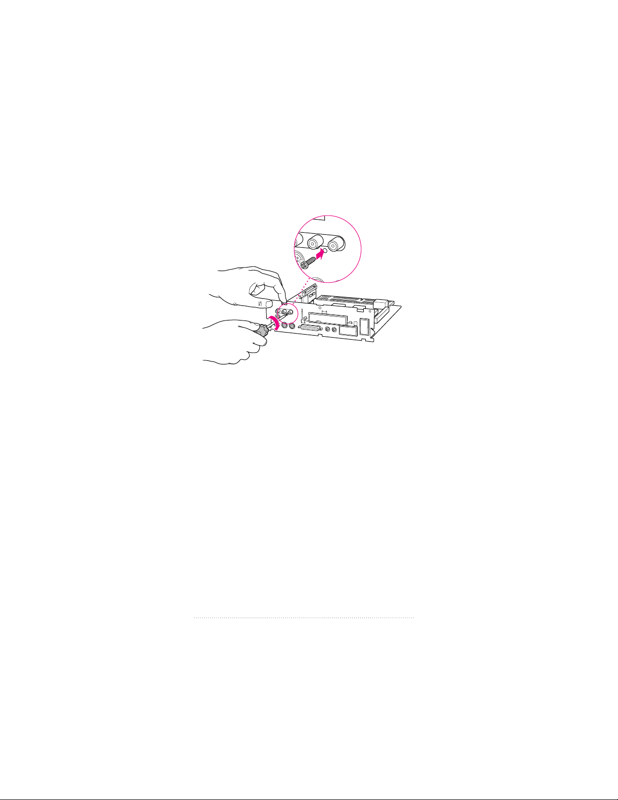
11 Screw the card to the vertical plate on the logic board. (Use
the provided attachment screw.)
12
Chapter 1
12 Swing the wire handle on the logic board back up into its
storage position, securing it under its catch. Then fit the
logic board into the guide rails on both sides of the
computer’s interior.
Make sure the logic board slides
into the guides that are on both
sides of the computer’s interior.
Swing the handle up, into its storage position.
13
Installing the Card and Software and Connecting Video Equipment
13 Press the reset button on the logic board. Then gently but
firmly push the board back into place within the computer.
You will need to push a little harder at the end to make
sure the connectors at the back of the board are seated in
their slot.
Note: If you can’t find the reset button, it may be in a
different location on your logic board. Check the manual
that came with your computer, in the section in the
appendix about installing expansion cards. An illustration
there shows where the reset button is for your computer.
1 Press the reset button.
2 Gently but
firmly push on the
vertical plate until the logic
board is solidly back in place.
14
Chapter 1
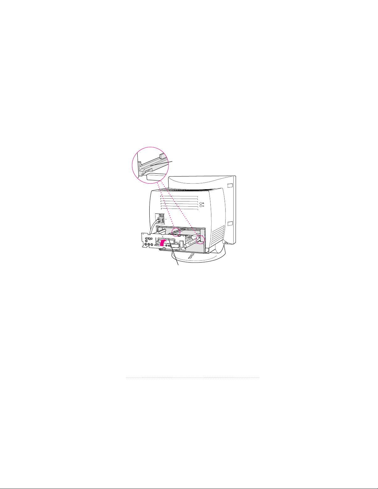
14 Slip the three tabs at the top of the back panel into the
matching grooves in the computer case.
15 Snap the bottom of the panel into place, making sure it is
flush with the back of the computer.
Snap the plastic back panel into place.
Slip the three tabs on the
back panel into the grooves
in the computer case.
15
Installing the Card and Software and Connecting Video Equipment
16 Reinsert the screws in the back panel.
Note: As described earlier, your computer may have only
two screws to reinsert, one on either side of the back panel.
17 Reconnect any cables you disconnected at the start of this
process.
Because you pressed the reset button on the logic board
earlier, some of your computer’s software settings may have
changed. (For example, the date and time on your computer
will need to be reset.) You may want to open the control
panels for the date and time, keyboard, and mouse to make
sure that they are set the way you want them. For more
information about resetting these options, see the “Setting
Options” or “Customizing Your Computer” topic of
Macintosh Guide, available in the Guide (h) menu. (If you
do not have Macintosh Guide on your computer, see the
manuals that came with your computer.)
Reinsert these screws.
(Your computer may have only two screws.)
16
Chapter 1

18 Skip the steps that follow (“Installing the Card in Style B”),
and the next section, “Installing the Card in a Modular
Computer,” and go on to the section titled “Installing
the Software.”
Installing the card in Style B
1 Make sure you save any open documents and quit any open
applications. Then turn off the computer.
m Choose Shut Down from the Special menu, or press the
Power key on the keyboard.
m Then press the power switch at the back of the computer.
Press the side of the switch marked with the j symbol.
2 Unplug all the cables except the power cord from your
computer.
Leaving the power cord plugged in helps protect the
computer from electrostatic discharge damage.
Important To avoid generating static electricity that may
damage components, do not walk around the room until
you have finished installing the card and closed the
computer. Additionally, move the logic board as little as
possible while it is outside the computer.
17
Installing the Card and Software and Connecting Video Equipment
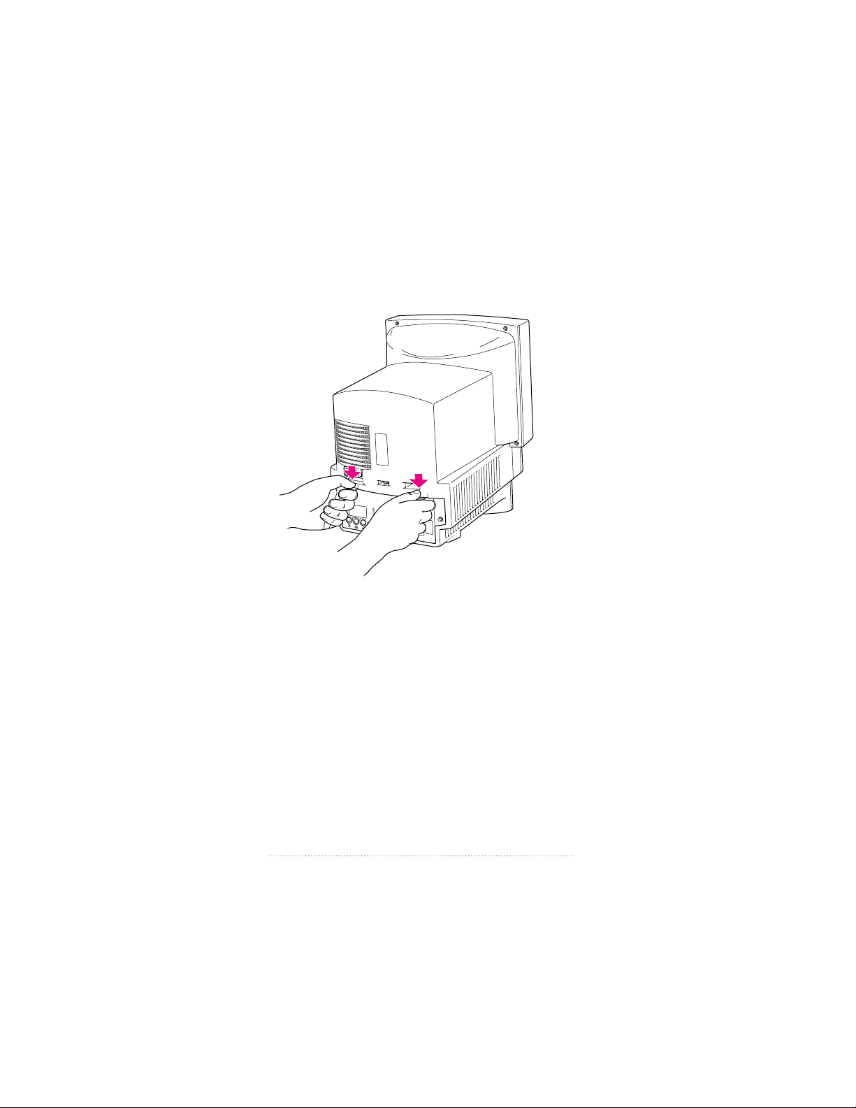
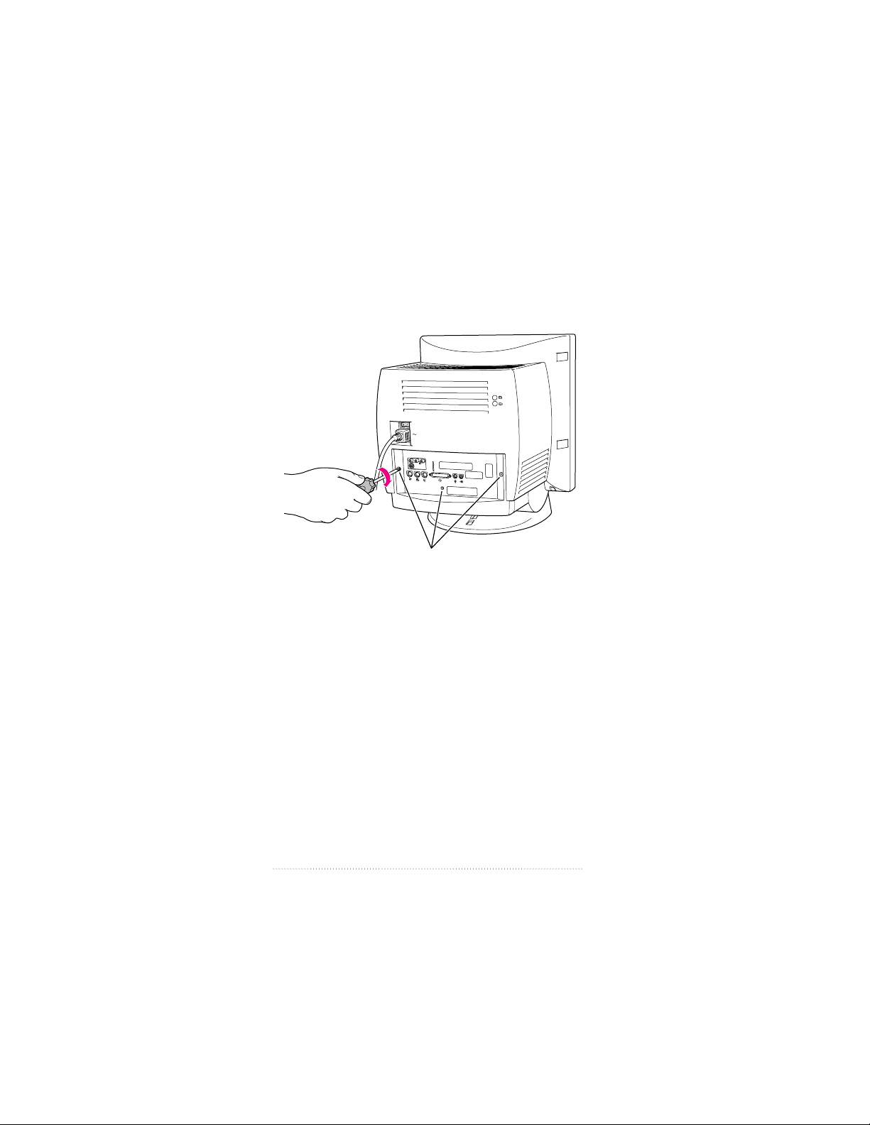
3 If there are screws securing the back panel, remove them
with a screwdriver. Then press down with your thumbs to
loosen the clips on either side of the back panel.
18
Chapter 1
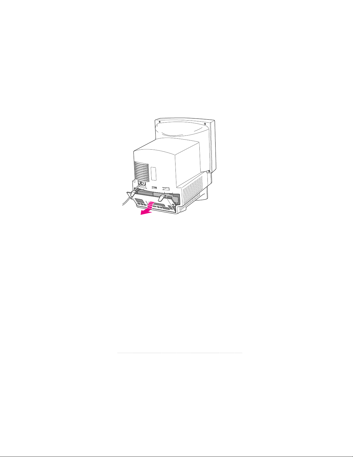
4 Pulling gently, swing the panel down and slip it out.
19
Installing the Card and Software and Connecting Video Equipment
5 Remove both retainer screws from the vertical plate behind
the back panel.
Remember: Don’t walk around the room until you have
finished installing the card and closed the computer. Move
the logic board as little as possible while it’s outside the
computer.
Remove both retainer screws from the vertical plate.
20
Chapter 1
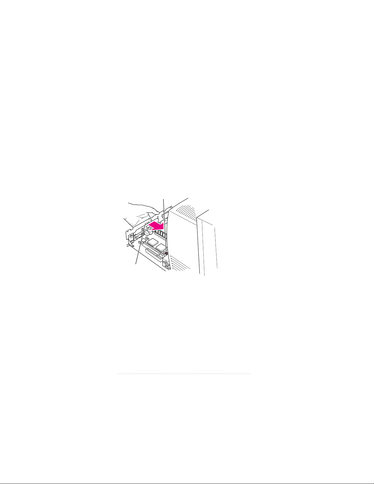
6 There is a wire handle on the back of the logic board. Swing
it down and use it to pull the logic board toward you.
The logic board is plugged into a slot inside the computer.
You may have to brace the computer with your other hand
and pull firmly at first. Slide the entire logic board all the way
out of the computer.
Swing down the wire handle, and slide
the logic board out of the computer.
21
Installing the Card and Software and Connecting Video Equipment
7 Locate the video-in access cover on one side of the vertical
plate attached to the logic board. Remove the cover from
this opening by squeezing together the plastic tabs that hold
it in place.
Note: Your logic board may not look exactly like the one
pictured here, but the video-in slot and access cover are in
the same position regardless of the logic board you have.
Video-in slot
Vertical plate
Plastic tabs
The plastic access cover is on the
other side of the vertical plate.
Metal retainer
22
Chapter 1
8 Remove the video input card from its static-proof bag.
Handle the card by its edges in order to avoid touching
the connectors.
9 Attach the grounding clip to the S-video port of the video
input card, if it isn’t attached already.
Important Without the grounding clip attached, the
S-video port may send insufficient power to equipment
you connect to it.
Grounding clip
S-video port
23
Installing the Card and Software and Connecting Video Equipment
 Loading...