


 Loading...
K Service Source
Macintosh 12 RGB Display
K Service Source
Specifications
Macintosh 12" RGB Display
Specifications |
Characteristics - 1 |
|
|
|
|
Characteristics
Picture Tube
12-in. viewable diagonal screen
90° deflection angle; black matrix-type dot screen Phosphor type P22 (aluminized)
Spherical, antiglare surface
Screen Resolution
512x384 lines; 64 dpi
Displays up to 256 colors with Macintosh Display Card 4•8 and 16.7 million colors with Macintosh Display Card 8•24
Scan Rates |
Vertical refresh rate: 60.15 Hz |
|
Horizontal scan rate: 24.48 kHz |
|
Rise and fall time: 27 ns maximum |

|
Specifications |
Characteristics - 2 |
|||
|
|
|
|
||
Active Video |
8.08 in. by 6.02 in. (205 mm by 153 mm) |
||||
Display Area |
|
|
|
|
|
Input Signals |
Video: red, green, and blue analog video; RS-343 standard |
||||
|
|
|
|
|
|
|
|
|
|
|
|

Specifications |
Controls - 3 |
|
|
|
|
Controls
User Controls
Rear panel: power switch
Right side: brightness and contrast controls
Specifications |
Physical and Electrical - 4 |
|
|
|
|
Power Supply (International)
Physical and Electrical
Universal power supply
Voltage: 90–270 VAC, self-configuring Frequency: 47–63 Hz, single-phase Power: 90 W maximum
Power Supply (Domestic)
Size and Weight
Voltage: 100–120 VAC Frequency: 50–60 Hz Power: 90 W maximum
Height: 12.2 in. (310 mm) Width: 14.4 in. (365 mm) Depth: 10.0 in. (253 mm) Weight: 35 lb. (15.9 kg)

Specifications |
Operating Environment - 5 |
|
|
|
|
Temperature
Humidity
Altitude
Operating Environment
50°F–104°F (10°C–40°C)
95% maximum, noncondensing
10,000 ft. (3,048 m) maximum
104°F (40°C) operation from 0–7000 ft. (2,134 m) and derated linearly to maximum 64°F (25°C) at 10,000 ft.
K Service Source
Troubleshooting
Macintosh 12" RGB Display
Troubleshooting |
General - 1 |
|
|
General
The Symptom Charts included in this chapter will help you diagnose specific symptoms related to your product. Because cures are listed on the charts in the order of most likely solution, try the first cure first. Verify whether or not the product continues to exhibit the symptom. If the symptom persists, try the next cure. (Note: If you have replaced a module, reinstall the original module before you proceed to the next cure.)
If you are not sure what the problem is, or if the Symptom Charts do not resolve the problem, refer to the Flowchart for the product family.
For additional assistance, contact Apple Technical Support.

 Troubleshooting Symptom Charts/No Raster - 2
Symptom Charts
No Raster
No raster, LED off |
1 |
Ensure monitor’s video cable is connected to the computer or |
||
|
|
the video card in the computer. |
||
|
2 |
Check power cord. |
||
|
3 |
Check internal power connectors. |
||
|
4 |
Replace blown fuse. |
||
|
5 |
Replace external power cable assembly. |
||
|
6 |
Replace main deflection board. |
||
No raster, LED on |
1 |
Ensure monitor’s video cable is connected to the computer or |
||
|
|
the video card in the computer. |
||
|
2 |
Adjust contrast and brightness user controls. |
||
|
3 |
Verify that video card in monitor is working properly. |
||
|
4 |
Check main deflection board and CRT/video board connectors. |
||
|
5 |
Replace blown fuse. |
||
|
6 |
Perform screen adjustment. |
||
|
7 |
Replace main deflection board. |
||
|
8 |
Replace CRT/video board. |
||
|
9 |
Replace CRT. |
||
|
|
|
|
|
|
|
|
|
|
 Troubleshooting Symptom Charts/Geometry - 3
Geometry
Raster size short/ |
1 |
Adjust V-HEIGHT or H-WIDTH controls on main deflection |
tall, narrow/wide |
|
board. |
|
2 |
Replace main deflection board. |
|
3 |
Replace CRT. |
Raster not centered |
1 |
Verify that distortion is not due to environmental conditions. |
|
|
Move monitor to another location. |
|
2 |
Adjust H-CENT or V-CENT external controls. |
|
3 |
Replace main deflection board. |
Horizontal linearity |
Replace main deflection board. |
|
bad (screen sides |
|
|
differ) |
|
|

|
|
Troubleshooting |
|
Symptom Charts/Geometry (Continued) - 4 |
|
|
|
|
|
|
|
|
|
|
Geometry (Continued) |
||
|
|
|
|||
Vertical linearity bad |
1 |
Adjust V-LIN control on main deflection board. |
|||
(screen top and |
2 |
Replace main deflection board. |
|||
bottom differ) |
|
|
|
||
Raster bows |
1 |
Verify that distortion is not due to environmental conditions. |
|||
|
|
|
|
Move monitor to another location. |
|
|
|
|
2 |
Check V-HEIGHT and V-CENT adjustment controls and H- |
|
|
|
|
|
WIDTH and H-CENT controls. (Some bowing from |
|
|
|
|
|
environmental conditions is normal and is within |
|
|
|
|
|
manufacturing tolerances. Slight bowing does not impair |
|
|
|
|
|
functionality of monitor.) |
|
|
|
|
3 |
Replace main deflection board. |
|
|
|
|
4 |
Replace CRT. |
|

|
|
Troubleshooting |
|
|
Symptom Charts/Geometry (Continued) - 5 |
|
|
|
|
|
|
||
|
|
|
Geometry (Continued) |
|||
|
|
|
||||
Entire raster is tilted |
1 |
Verify that distortion is not due to environmental conditions. |
||||
|
|
|
|
Move monitor to another location. |
||
|
|
|
2 |
Adjust yoke assembly as follows: |
||
|
|
|
|
• |
Switch off power and remove rear cover |
|
|
|
|
|
• Loosen frontmost screw on neck of CRT |
||
|
|
|
|
• |
Twist yoke assembly as appropriate |
|
|
|
|
|
• |
Retighten screw on neck of CRT (Do not overtighten screw; |
|
|
|
|
|
|
you could break neck of CRT.) |
|
|
|
|
|
• |
Switch on monitor and check display |
|
|
|
|
3 |
Replace main deflection board. |
||

|
Troubleshooting |
|
Symptom Charts/Geometry (Continued) - 6 |
||
|
|
|
|||
|
|
Geometry (Continued) |
|||
Abnormal/distorted |
1 |
Verify that distortion is not due to environmental conditions. |
|||
raster (other than |
|
Move monitor to another location. |
|||
above) |
2 |
Check all cable connections. |
|||
|
|
3 |
Perform geometric adjustments. |
||
|
|
4 |
Replace main deflection board. |
||
|
|
5 |
Replace CRT/video board. |
||
|
|
6 |
Replace CRT. |
||
|
|
|
|
|
|
|
|
|
|
|
|
 Troubleshooting Symptom Charts/Synchronization - 7
Synchronization
Picture breaks into |
1 |
Connect another monitor to computer and verify video signal. |
||
diagonal lines |
2 |
Adjust H-HOLD control on main deflection board. |
||
|
3 |
Replace main deflection board. |
||
Picture rolls |
1 |
Verify that video card in monitor is working properly. |
||
vertically |
2 |
Adjust V-HOLD control on main deflection board. |
||
|
3 |
Replace main deflection board. |
||
Single vertical or |
1 |
Check yoke connector DY. |
||
horizontal line on |
2 |
Replace main deflection board. |
||
screen |
3 |
Replace CRT. |
||
|
|
|
|
|
|
|
|
|
|

 Troubleshooting Symptom Charts/Video - 8
Video
Predominant red, |
1 |
Check video cable connection. |
blue, or green tint |
2 |
Verify that video card in monitor is working properly. |
|
3 |
Perform white balance adjustments. |
|
4 |
Replace CRT/video board. |
|
5 |
Replace CRT. |
Picture too dark or |
1 |
Adjust contrast and brightness knobs. |
too bright |
2 |
Verify that video card in monitor is working properly. |
|
3 |
Perform video adjustments (cutoff and white balance). |
|
4 |
Replace main deflection board. |
|
5 |
Replace CRT/video board. |
|
6 |
Replace CRT. |

|
Troubleshooting |
|
Symptom Charts/Video (Continued) - 9 |
||
|
|
|
|||
|
|
Video (Continued) |
|||
Cannot adjust |
1 |
Replace contrast/brightness assembly. |
|||
brightness, contrast, |
2 |
Replace main deflection board. |
|||
or color |
3 |
Replace CRT/video board. |
|||
Out of focus |
1 |
Adjust focus control on flyback transformer. |
|||
|
|
2 |
Perform screen adjustment. |
||
|
|
3 |
Replace main deflection board. |
||
|
|
4 |
Replace CRT. |
||
|
|
|
|
|
|
|
|
|
|
|
|

 Troubleshooting Symptom Charts/Miscellaneous - 10
Miscellaneous
Intermittently shuts |
1 |
Ensure monitor’s video cable is connected to the computer or |
||
down |
|
the video card in the computer. |
||
|
2 |
Replace main deflection board. |
||
Picture jitters or |
1 |
Check that ground cables are secure. |
||
flashes |
2 |
Check that adjacent computer equipment is properly |
||
|
|
grounded. Move other electrical devices away from monitor. |
||
|
|
Shut off fluorescent lights. |
||
|
3 |
Replace main deflection board. |
||
Flashing or wavy |
1 |
Crimp metal connector tabs on video connector. |
||
screen |
2 |
Replace main deflection board. |
||
Black spots on screen |
Replace CRT. |
|||
(burnt phosphors) |
|
|
|
|
|
|
|
|
|
|
|
|
|
|

K Service Source
Take Apart
Macintosh 12" RGB Display
 Take Apart
Rear Cover
Rear Cover - 1
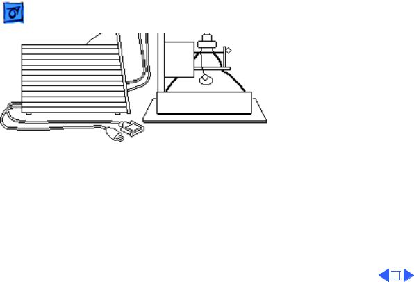
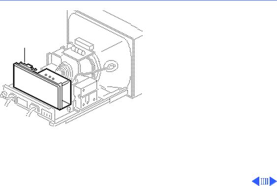
Rear Cover
No preliminary steps are required before you begin this procedure.
±Warning: This product contains high voltage and a high-vacuum picture tube. To prevent serious injury, review CRT safety in Bulletins/Safety.
Take Apart |
Rear Cover - 2 |
|
|
|
|
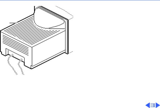
1 |
Place the monitor face- |
|
|
down on a protective pad |
|
|
and remove the two case |
|
|
screws. |
|
2 |
Separate the bottom of |
|
|
the rear cover from the |
|
|
bezel. |
|
Take Apart |
Rear Cover - 3 |
|
|
|
|
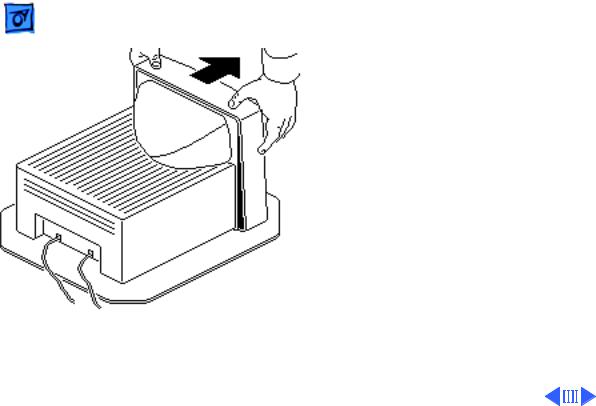
3 |
Set the monitor upright. |
|
4 |
Press down about one |
|
|
inch from the outside |
|
|
edges of the bezel to |
|
|
separate the top of the |
|
|
rear cover from the |
|
|
bezel. |
|
Take Apart |
Rear Cover - 4 |
|||
|
|
|
|
|
5 |
Place the monitor face- |
|||
|
down on a protective pad. |
|||
6 |
Lift off the loosened |
|||
|
rear cover. |
|||
7 |
Pull the AC power cord |
|||
|
and video cable through |
|||
|
the cover. |
|||
|
|
|
|
|
|
|
|
|
|

 Take Apart
Contrast/Brightness
Assembly
Contrast/Brightness Assembly - 5
Contrast/
Brightness
Assembly
Before you begin,
• Remove the rear cover
• Discharge the CRT
• Remove the anode cap
±Warning: This product contains high voltage and a high-vacuum picture tube. To prevent serious injury, review CRT safety in Bulletins/Safety.
±Warning: Never use a
Take Apart |
Contrast/Brightness Assembly - 6 |
|
|
|
|
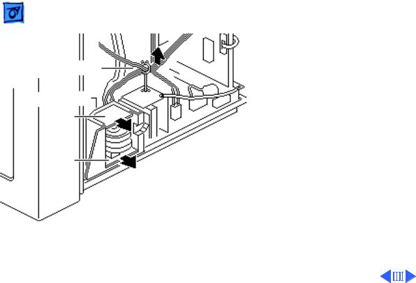
Cable Retainer
Mounting Bracket
VR204
VR203
grounding wriststrap until after discharging the CRT.
J204 1 Disconnect the six-wire cable from connector J204 on the CRT/video board. Remove the six wires from the cable retainer.
2Remove brightness board VR204 and contrast board VR203 from the mounting bracket.
3Unhook and pull the six wires through the back of the mounting bracket.
Take Apart |
Contrast/Brightness Assembly - 7 |
|
|
|
|
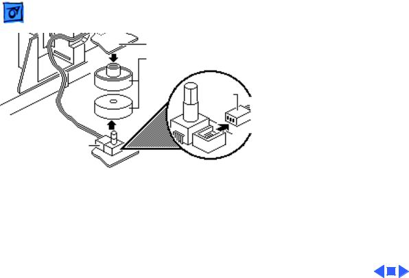
J206
Brightness Board - VR204
Plastic Control Knobs
J205
Contrast Board
VR203
4Pull off the two control knobs.
5Disconnect cable connector J206 from the brightness board and cable connector J205 from the contrast board.
 Take Apart
Fuse
Fuse - 8
Fuse
Before you begin,
• Remove the rear cover
• Discharge the CRT
• Remove the anode cap
±Warning: This product contains high voltage and a high-vacuum picture tube. To prevent serious injury, review CRT safety in Bulletins/Safety.
±Warning: Never use a grounding wriststrap until after discharging the CRT.

Take Apart |
Fuse - 9 |
|
|
|
|
|
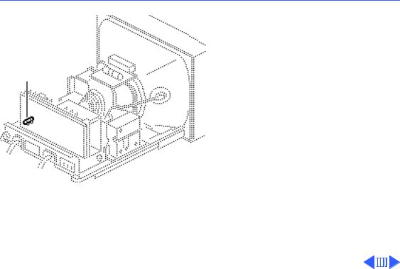
Using a small flat-blade |
|
|
screwdriver, pry the |
|
|
defective fuse from |
|
|
connector F901 on the |
|
|
deflection board. |
|
F901
 Take Apart
CRT/Video Board
CRT/Video Board - 10
CRT/Video Board
Before you begin,
• Remove the rear cover
• Discharge the CRT
• Remove the anode cap
±Warning: This product contains high voltage and a high-vacuum picture tube. To prevent serious injury, review CRT safety in Bulletins/Safety.
±Warning: Never use a grounding wriststrap until after discharging the CRT.
Take Apart |
CRT/Video Board - 11 |
|
|
|
|
|
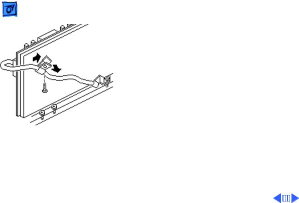
1 Remove the screw that |
|
|
secures the video cable |
|
|
to the cable clamp at the |
|
|
back of the CRT/video |
|
|
board. |
|
|
2 Remove the video cable |
|
|
from the clamp and |
|
|
remove the clamp from |
|
|
the CRT/video board. |
|
Loading...