

Apple PowerBook G4 (12-inch 1.5 GHz) 05-10 Service Manual

Service Source
PowerBook G4 (12-inch 1.5 GHz)
Updated October 25, 2005
© 2005 Apple Computer, Inc. All rights reserved.

Service Source
Take Apart
PowerBook G4 (12-inch 1.5 GHz)
© 2005 Apple Computer, Inc. All rights reserved.
General Information
Overview
Some of the key features that distinguish this computer from earlier notebook models
include:
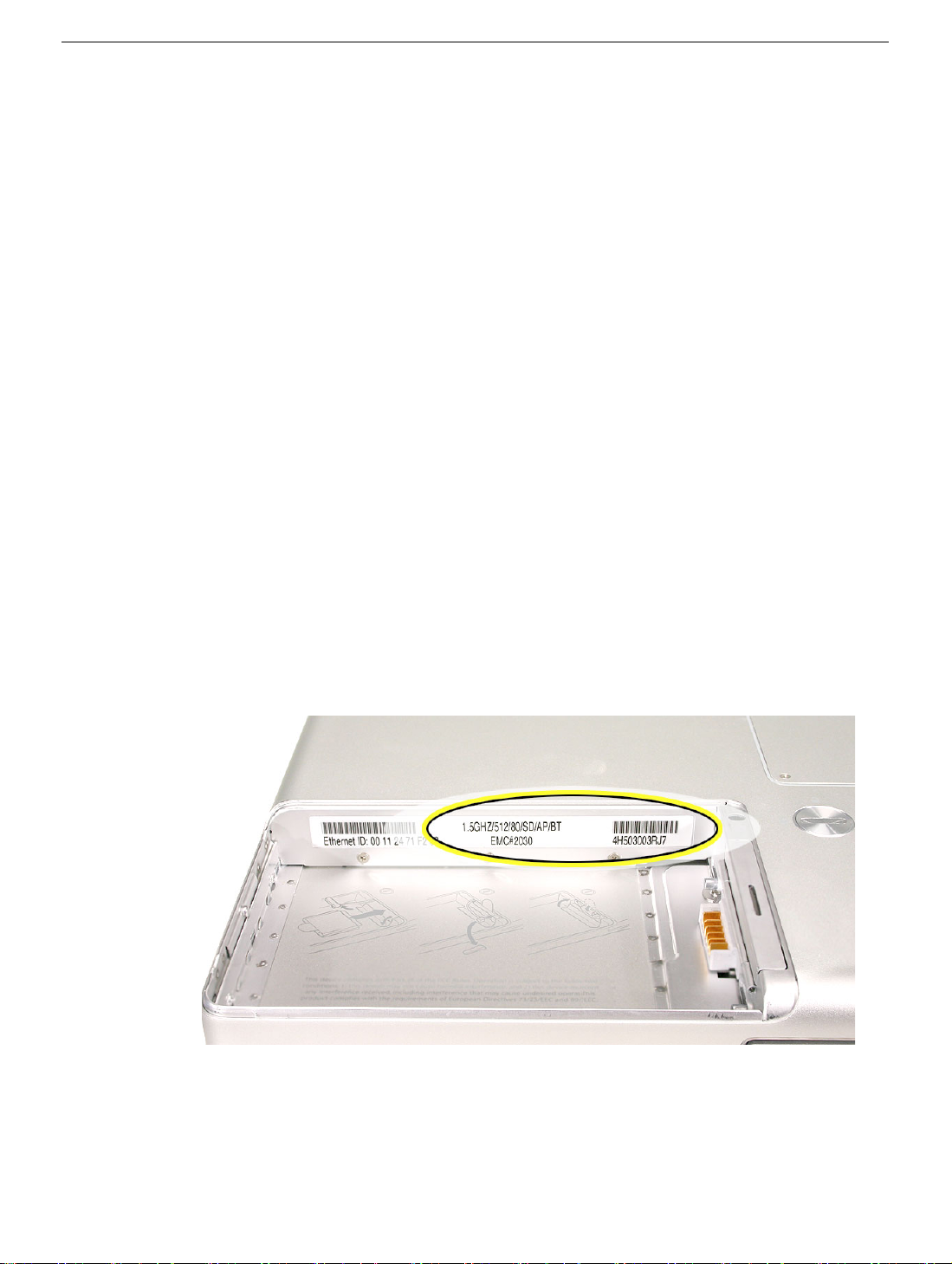
• Faster processor speed: 1.5 GHz (shown on serial number label)
• AirPort Extreme Card installed
• Sudden Motion Sensor (SMS)—Sudden Motion Sensor technology is a built-in feature
General Information
on the logic board that helps protect the hard drive if the computer is dropped or
experiences severe vibration. If the sensor detects motion beyond a preset trigger
point, it sends a signal to instantly park the drive heads. This action helps reduce the
risk of damage to the hard drive on impact.
In some environments, such as live concert halls, recording studios, or
Note:
dance clubs, external vibrations may be major enough to cause the sensor to
trigger unexpectedly, resulting in interrupted sound or video playback. Refer
to the Troubleshooting chapter for instructions on how to disable SMS.
Note:
In some locations you may see the Sudden Motion Sensor referred to as
the Mobile Motion Module. Both names refer to the same feature.
PowerBook G4 (12-inch 1.5 GHz) Take Apart -
1

• Scrolling Trackpad—A new trackpad feature allows faster navigation in windows with
scroll bars. To scroll or pan vertically, move two adjoining fingers up or down the
trackpad. To scroll or pan horizontally, move two adjoining fingers left or right on the
trackpad. You can customize this feature or turn it off in the Keyboard & Mouse pane
of System Preferences.
Note:
If you find that the pointer moves as you type because you accidentally
brush the trackpad, make sure that the "Ignore accidental trackpad input"
option in the Keyboard & Mouse pane of System Preferences is selected. For
more information on using the trackpad, choose Help > Mac Help from the
menu bar at the top of the screen.
Configuration Table
This table shows the PowerBook G4 (12-inch 1.5GHz) configurations at initial product
introduction:
Configuration M9690LL/A M9691LL/A
Video RAM 32 VRAM 32 VRAM
Processor 1.5 GHz 1.5 GHz
Optical Drive Combo (DVD-ROM/CD-
RW)
Hard Drive 60 GB, 5400 rpm
(100 GB CTO option)
Memory 512 MB 333 MHz DDR
(256 MB RAM on board
plus 256 MB SO-DIMM in
expansion slot)
AirPort Extreme card installed card installed
SuperDrive (DVD ± RW/
CD-RW)
80 GB, 5400 rpm
(100 GB CTO option)
512 MB 333 MHz DDR
(256 MB RAM on board
plus 256 MB SO-DIMM in
expansion slot)
2 -
PowerBook G4 (12-inch 1.5 GHz) Take Apart
General Information
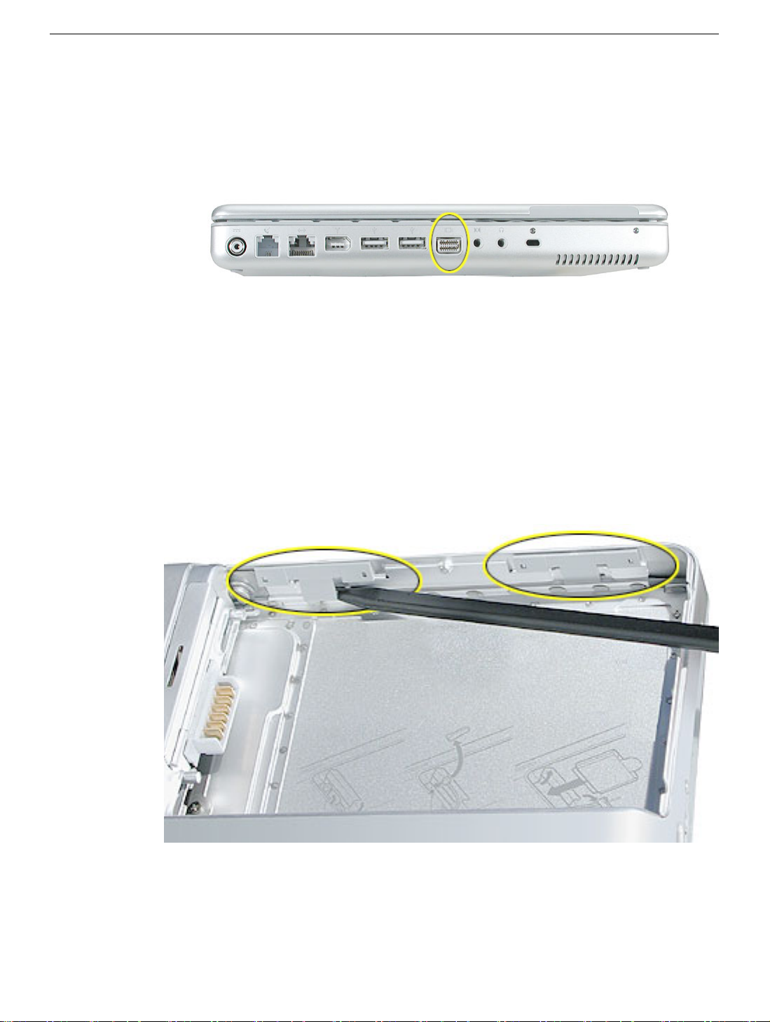
Model Differences
The external housing of the PowerBook G4 (12-inch 1.5 GHz) model looks the same as on
the PowerBook G4 (12-inch 1.33 GHz) model. Both have a mini-DVI port (shown below),
and both have two latches inside the battery bay.
The mini-DVI port is used with an adapter cable to connect the computer to a monitor,
television, VCR, or other video device. The adapter cables that can be used with this port
include a mini-DVI-to-DVI adapter, a mini-DVI-to-VGA adapter, and a mini-DVI-to-S-Video
adapter.
To distinguish the PowerBook G4 (12-inch 1.5 GHz) model from previous models, check
the processor speed and note the latches in the battery bay.
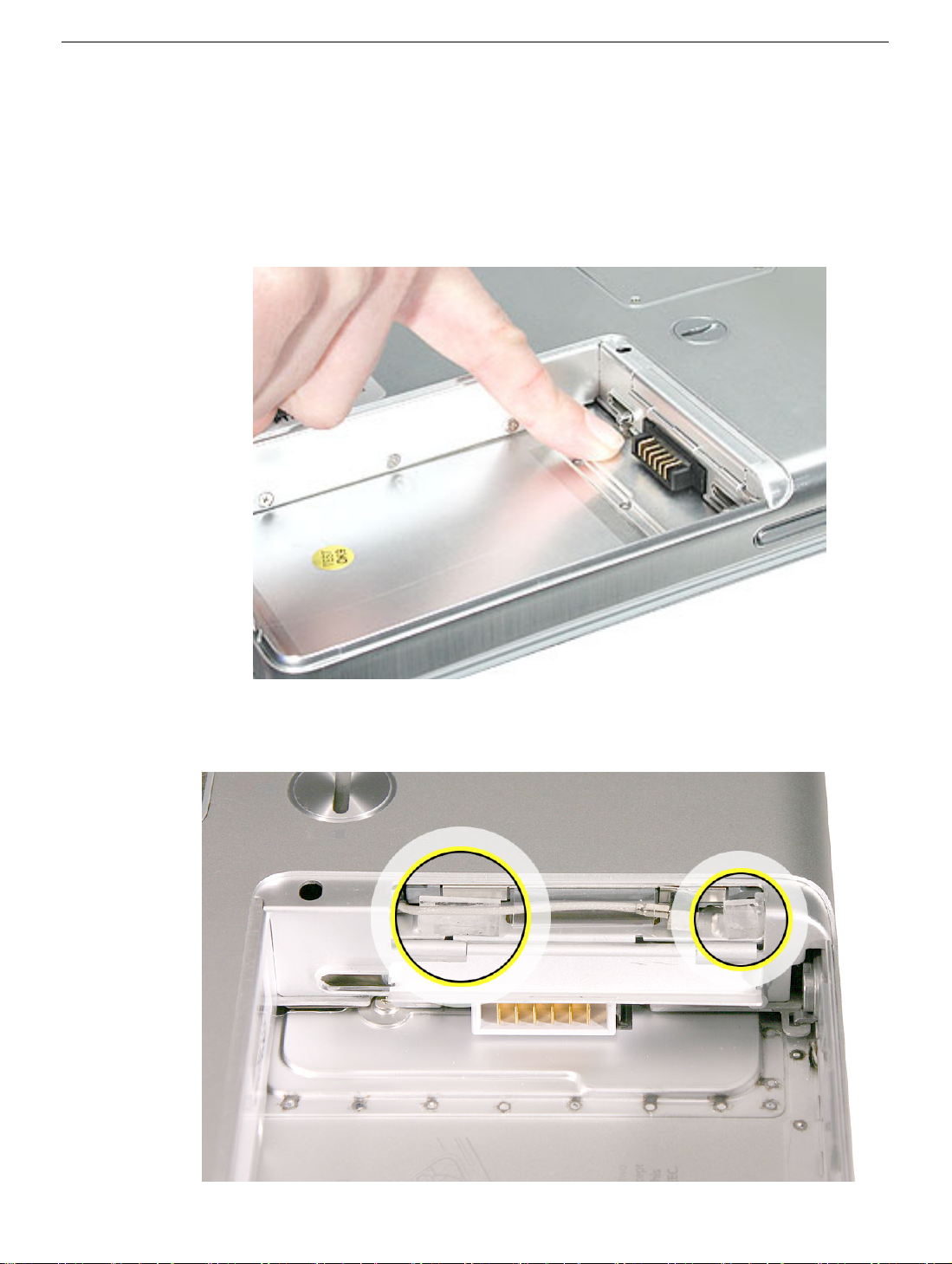
This computer model includes two latches inside the battery bay. These latches help
secure the top case to the computer. Refer to the Top Case procedure for more
information.
General Information
PowerBook G4 (12-inch 1.5 GHz) Take Apart -
3
Tools
The following tools are recommended for this computer:
• Coin
• ESD wriststrap and mat
• Small soft cloth
• Black stick (or other nonconductive nylon or plastic flat-blade tool)
• #0 Phillips screwdriver (magnetized)
• #1 Phillips screwdriver (magnetized)
• Jeweler’s flat-blade screwdriver
• 1.5 mm hex driver
• 4 mm socket wrench or needlenose pliers
• nonconductive tweezers or needlenose pliers (for replacing a foot or for routing thin
cables such as the AirPort antenna cable)
Important:
compartments (such as a plastic ice cube tray). If doing a complete disassembly, note the
screws removed from each location in the computer.
Warning: Check the screw lengths before installing the screws. Installing a longer
screw in the wrong place can permanently damage the housing or an internal part.
To organize the screws you remove from the computer, use a tray with divided
Serial Number Location
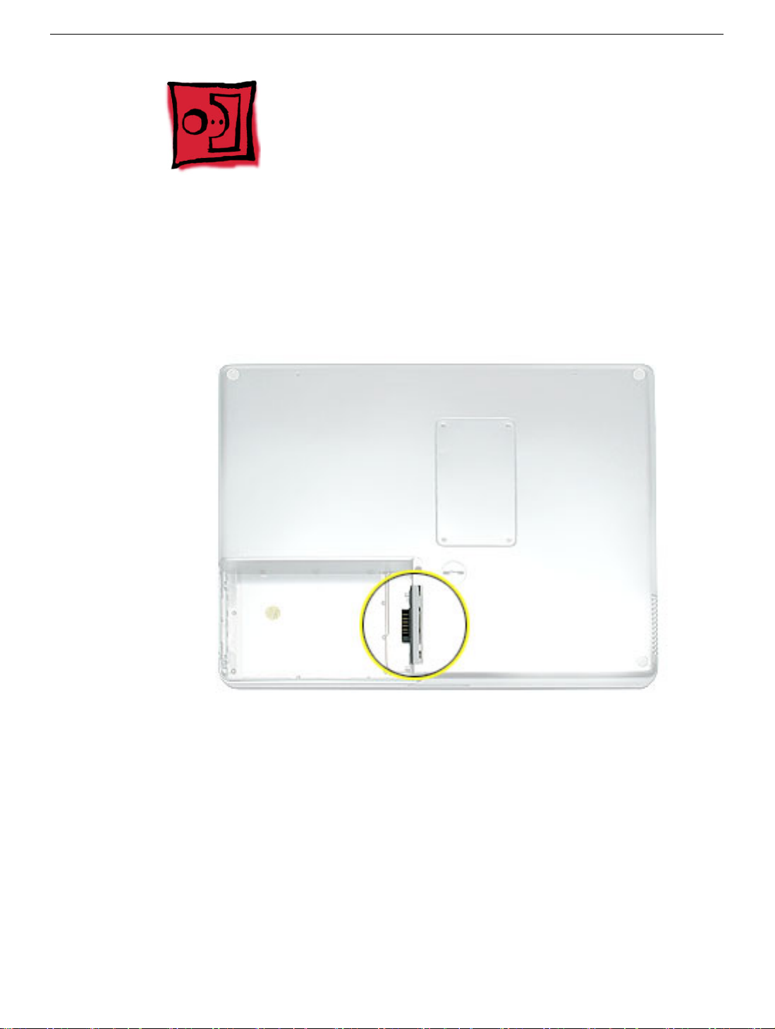
The serial number and processor speed are labeled in the battery bay.
4 -
PowerBook G4 (12-inch 1.5 GHz) Take Apart
General Information
Battery
Tools
This procedure requires the following tools:
• Soft cloth
• Coin
Part Location
Battery
Preliminary Steps
Warning: Always shut down the computer before opening it to avoid damaging its
internal components or causing injury. After you shut down the computer, the
internal components can be very hot. Let the computer cool down for 30 minutes
before continuing.
PowerBook G4 (12-inch 1.5 GHz) Take Apart -
5
Procedure
Warning:
performing this procedure.
1. Shut down the computer.
2. Unplug the power adapter, phone cord, and any other cables connected to the
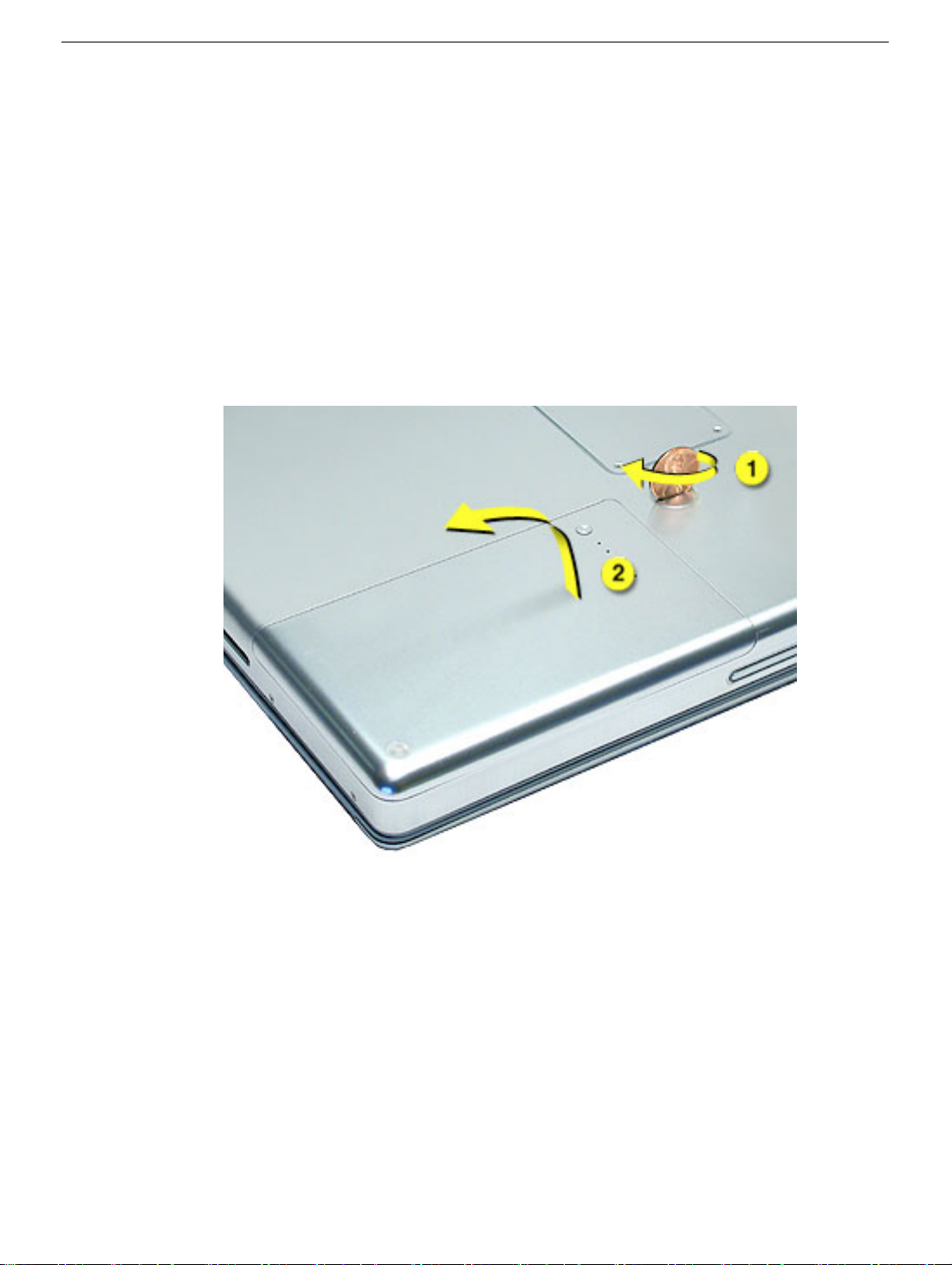
3. Turn over the computer and place it on a soft cloth.
4. Use a coin to release the battery lock.
5. Lift the battery out of the battery bay.
If the computer has been recently operating, allow it to cool down before
computer.
6. Install the replacement battery, and reassemble and test the computer.
6 -
PowerBook G4 (12-inch 1.5 GHz) Take Apart
Battery
Feet
Tools
This procedure requires the following tools:
• Foot kit
• Tweezers or needlenose pliers
• Soft cloth
Preliminary Step
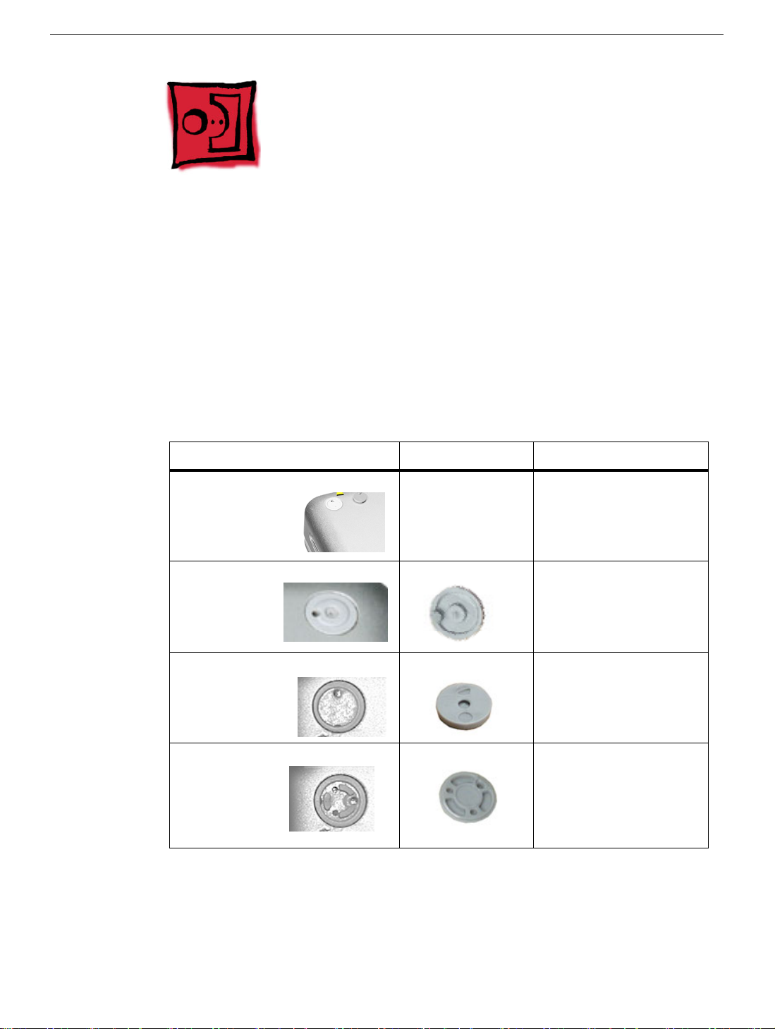
Before you begin, identify the type of foot that needs replacement. Check the bottom case
of the computer, and compare it with the images in this table:
Plug Area on Bottom Case Matching Foot Action
Missing plug Not available for
replacement
Battery plug Battery foot Continue with the
Case plug Case foot Continue with the
Case plug Case foot Continue with the
Do not perform the foot
replacement.
procedure, matching
the foot to the plug on
the battery.
procedure, matching
the foot to the plug on
the bottom case.
procedure, matching
the foot to the plug on
the bottom case.
Feet
PowerBook G4 (12-inch 1.5 GHz) Take Apart -
7
Procedure
Warning: The glue used in this procedure can bond instantly to skin. Do not touch the
glue. In the event of contact, review the safety instructions at the end of this document. For
additional information, refer to the glue manufacturer:
Elmer's Products, Inc.
Columbus, OH. 43215-3799
www.krazyglue.com
1. Place the computer upside down on a clean, lint-free cloth or other nonabrasive
surface.
2. Select a foot from the kit that matches the plug on the bottom case. (Refer to the
images shown in the table.) Do not use a foot that does not match.
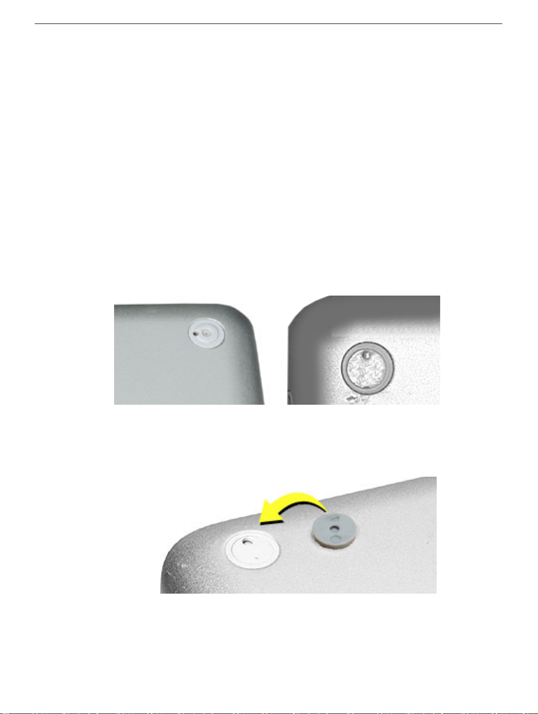
3. Make sure the plug area on the bottom case is clean. If any portion of the soft rubber
foot remains, remove it so that only the hard plastic plug is visible (as shown below).
Battery Plug Case Plug
Important: Notice the inner ring of the plug. When positioning the foot, make sure
the textured plane of the rubber foot fits into the compatible ring in the plug. This
ensures a balanced and level fitting.
8 - PowerBook G4 (12-inch 1.5 GHz) Take Apart
Feet

4. Warning: GLUE IS AN EYE AND SKIN IRRITANT. BONDS SKIN INSTANTLY. Do not
touch the glue at any time. Before opening the glue, review the safety instructions at
the end of this document.
Important: The glue tube included in the kit is sealed until first use. Do not break the
seal until you are ready to use the glue. To break the seal, hold the tube upright and
away from you. Place the hollow nozzle cap on the tube and tighten it all the way
down. The tube is then ready to dispense the glue through the nozzle cap.
5. Apply one drop of glue to the plug on the bottom case. Do not spread the glue.
6. Using tweezers or needlenose pliers, carefully position the new foot so its textured
surface fits into the inner ring of the plug.
7. Using the end of the tweezers or pliers—not your finger—lightly press and hold the
foot in place for 30 seconds.
8. Before turning over the computer, allow the glue to set for at least 15 minutes.
9. Discard the tube of glue.
SAFETY INSTRUCTIONS: GLUE IS AN EYE AND SKIN IRRITANT. BONDS SKIN
INSTANTLY. Contains ethyl cyanoacrylate. Avoid contact with skin and eyes. If eye or
mouth contact occurs, hold eyelid or mouth open and rinse thoroughly but gently with
water only for 15 minutes and GET MEDICAL ATTENTION. Liquid glue will sting eye
temporarily. Solidified glue may irritate eye like a grain of sand and should be treated by an
eye doctor. If skin bonding occurs, soak in acetone-based nail polish remover or warm
soapy water and carefully peel or roll skin apart (do not pull). Contact through clothing may
cause skin burn. If spilled on clothing, flush with cold water. Avoid prolonged breathing of
vapors. Use with adequate ventilation. KEEP OUT OF REACH OF CHILDREN.
Feet
PowerBook G4 (12-inch 1.5 GHz) Take Apart - 9
Memory Door and Memory Card
Tools
This procedure requires the following tools:
• Soft cloth
• #0 Phillips screwdriver
• Black stick (or other nonconductive nylon or plastic flat-blade tool)
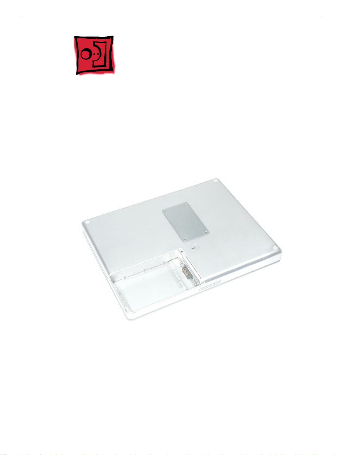
Part Location
Preliminary Steps
Before you begin, remove the battery.
Procedure
Warning: If the computer has been recently operating, allow it to cool down before
performing this procedure.
10 - PowerBook G4 (12-inch 1.5 GHz) Take Apart
Memory Door and Memory Card
1. Place the computer upside down on a soft cloth.
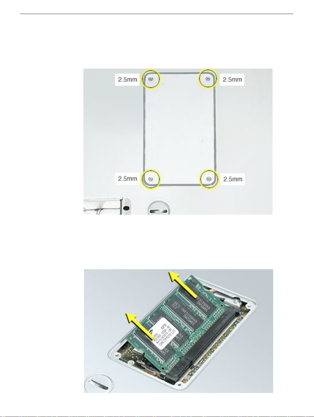
2. Remove the four identical screws from the memory door.
3. Use a black stick to lift off the memory door.
4. Touch a metal surface inside the computer to discharge static electricity from your
body.
5. If a memory card is already installed, release it by spreading apart the tabs in the
expansion slot from the notches in the card. Allow the card to pop up slightly, and pull
it out of the memory slot.
Memory Door and Memory Card
PowerBook G4 (12-inch 1.5 GHz) Take Apart - 11
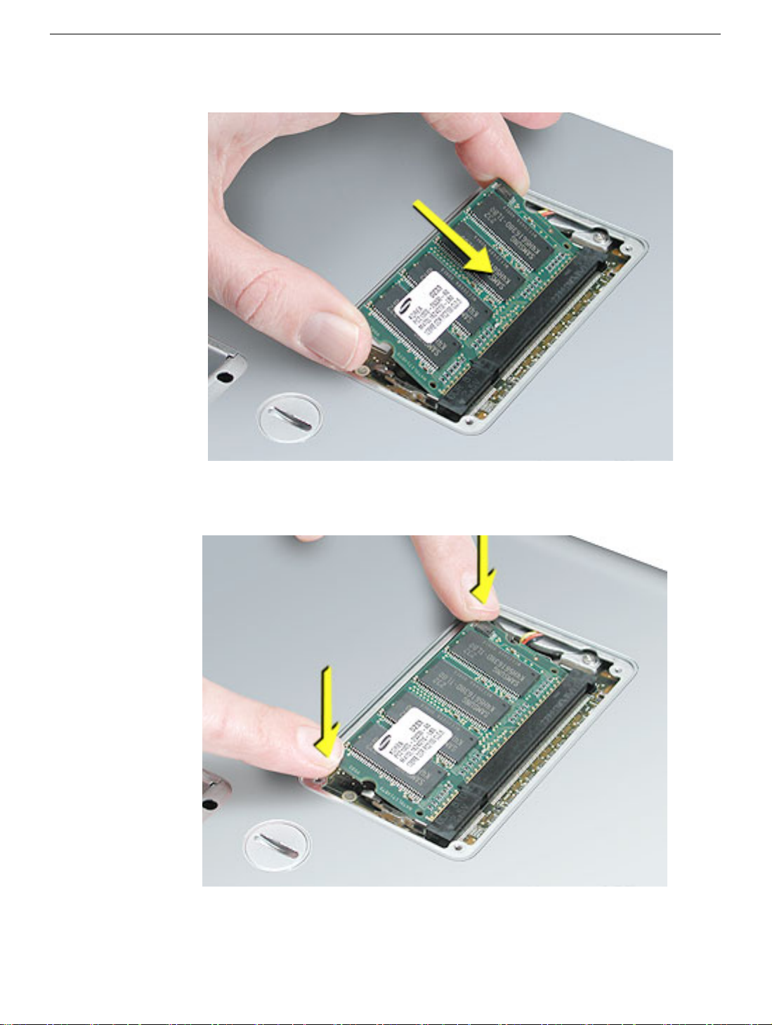
6. Insert the replacement memory card into the expansion slot at a 30-degree angle.
7. Make sure the memory card is fully inserted. Check that the notches in the card clear
the tabs as you press down on the sides of the card to lock it into place.
8. Install the memory door. Be careful not to overtighten the screws.
9. Install the battery, and test the computer.
12 - PowerBook G4 (12-inch 1.5 GHz) Take Apart
Memory Door and Memory Card
AirPort Extreme Card
Tools
This procedure requires a black stick (or other nonconductive nylon or plastic flat-blade
tool).
Part Location
Preliminary Steps
Before you begin, remove the battery.
AirPort Extreme Card
PowerBook G4 (12-inch 1.5 GHz) Take Apart - 13
Procedure
Warning: If the computer has been recently operating, allow it to cool down for 30
minutes before performing this procedure.
1. Touch a metal surface inside the battery bay to discharge static electricity from your
body.
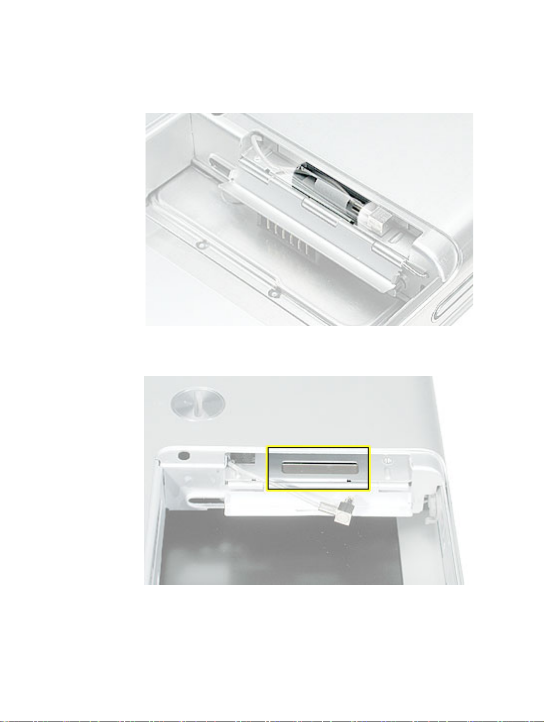
2. Open the door to the AirPort slot, and note the position of the two clear plastic card
stoppers.
14 - PowerBook G4 (12-inch 1.5 GHz) Take Apart
AirPort Extreme Card
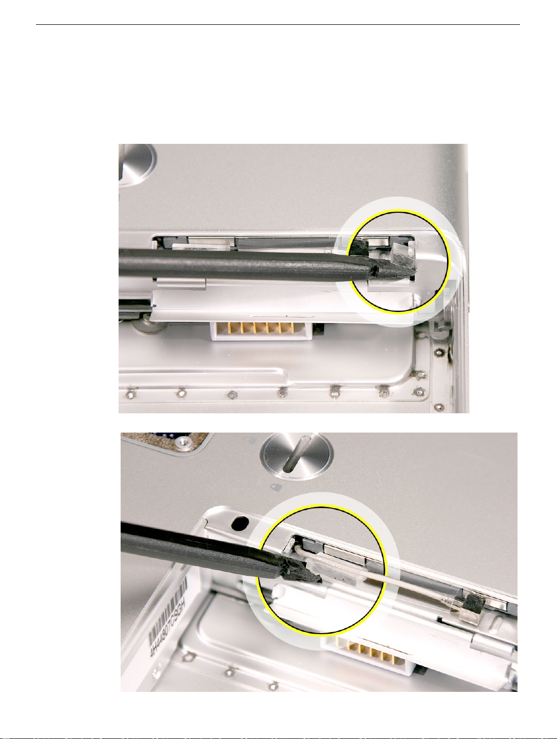
3. Pry up the two card stoppers.
Replacement Note:
The card stoppers are held in place with double-stick
adhesive. As long as the adhesive is still sticky, you can reuse the stoppers. If
the stoppers are no longer sticky, replace with new stoppers after installing
the AirPort Express Card.
AirPort Extreme Card
PowerBook G4 (12-inch 1.5 GHz) Take Apart - 15
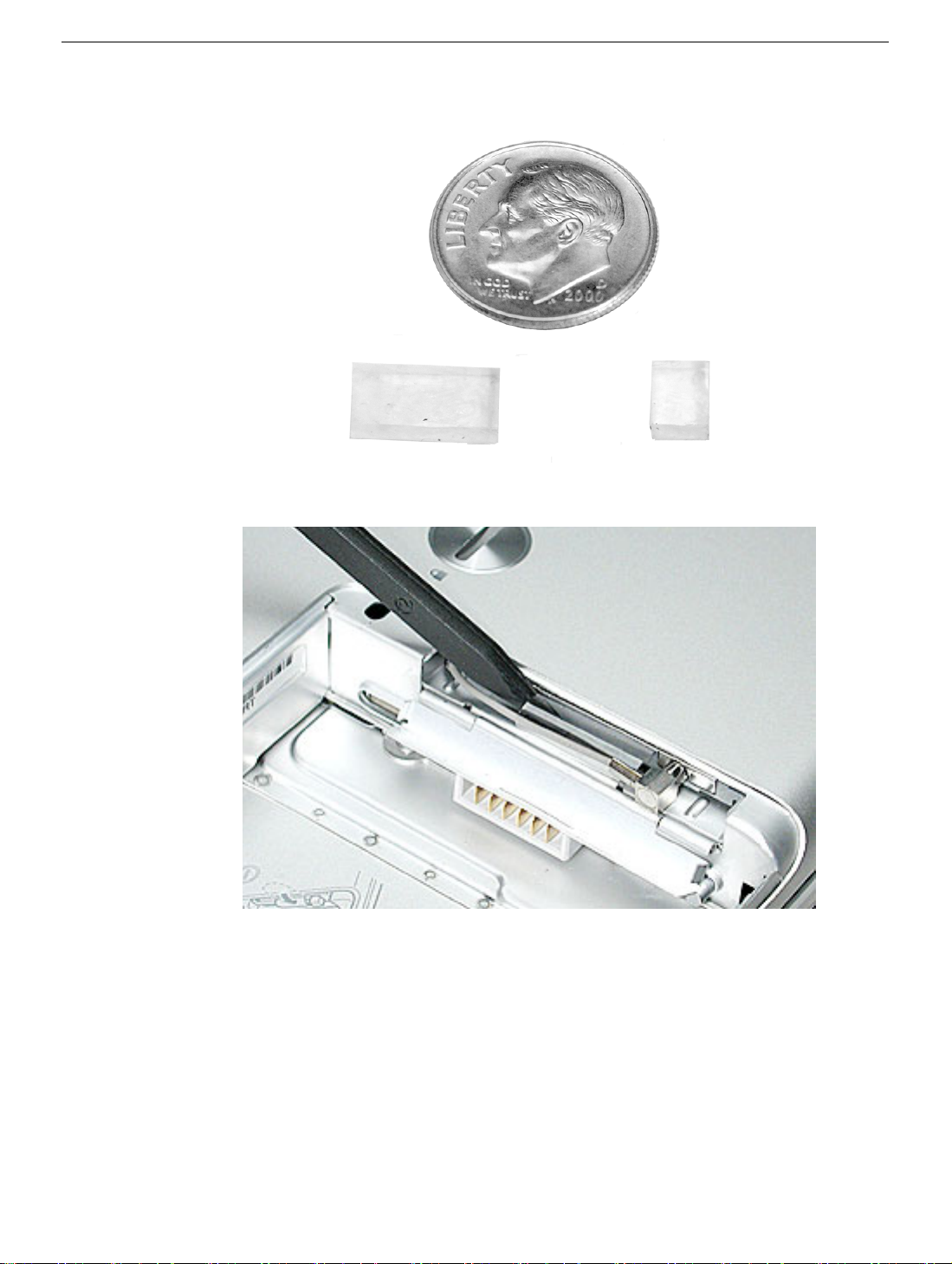
The following image shows the relative size of the two card stoppers:
Note:
4. Use a black stick to un-loop the pull tab.
16 - PowerBook G4 (12-inch 1.5 GHz) Take Apart
AirPort Extreme Card
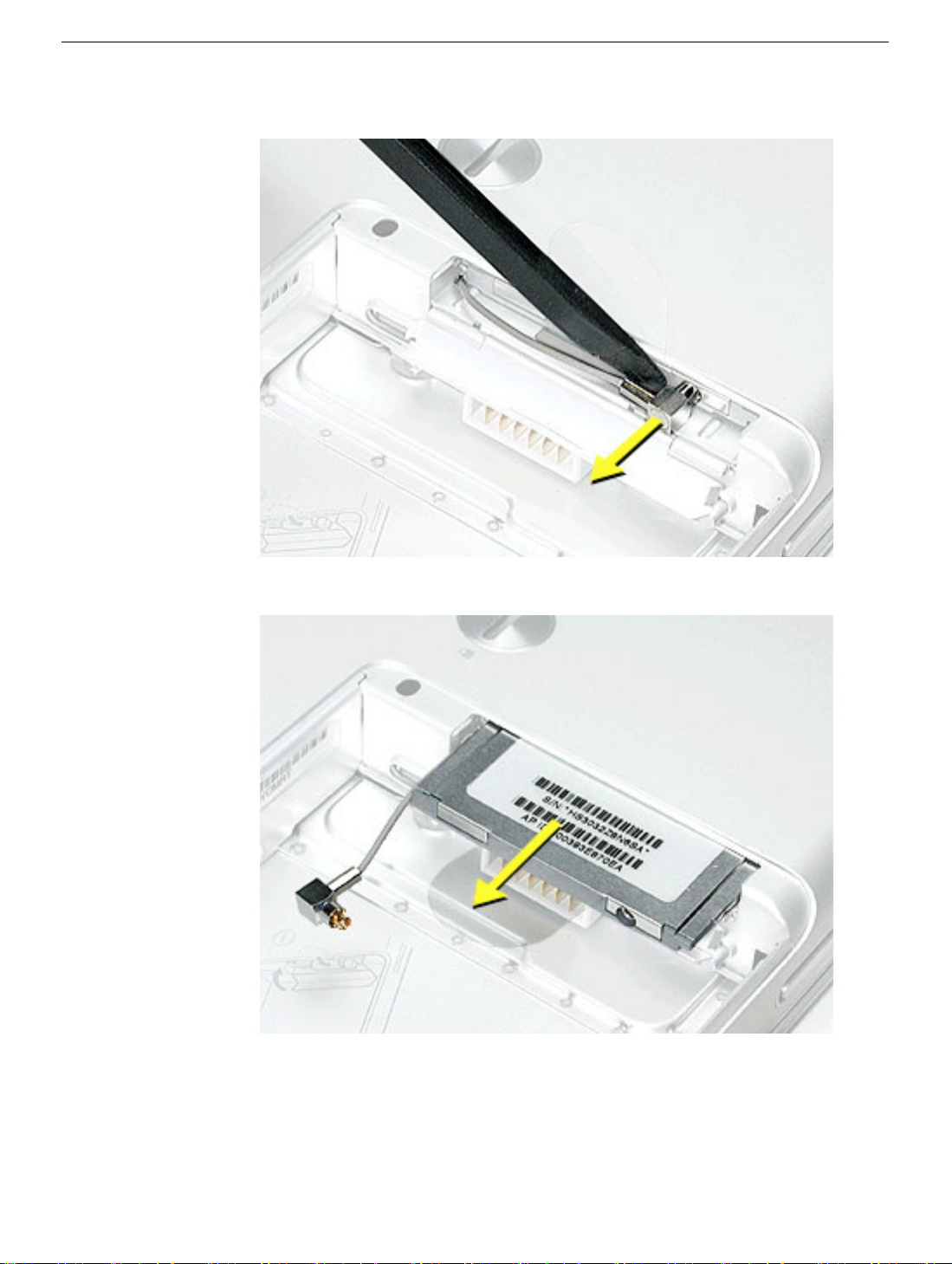
5. Gently disconnect the AirPort antenna cable.
6. Use the pull tab to pull out the card.
AirPort Extreme Card
PowerBook G4 (12-inch 1.5 GHz) Take Apart - 17
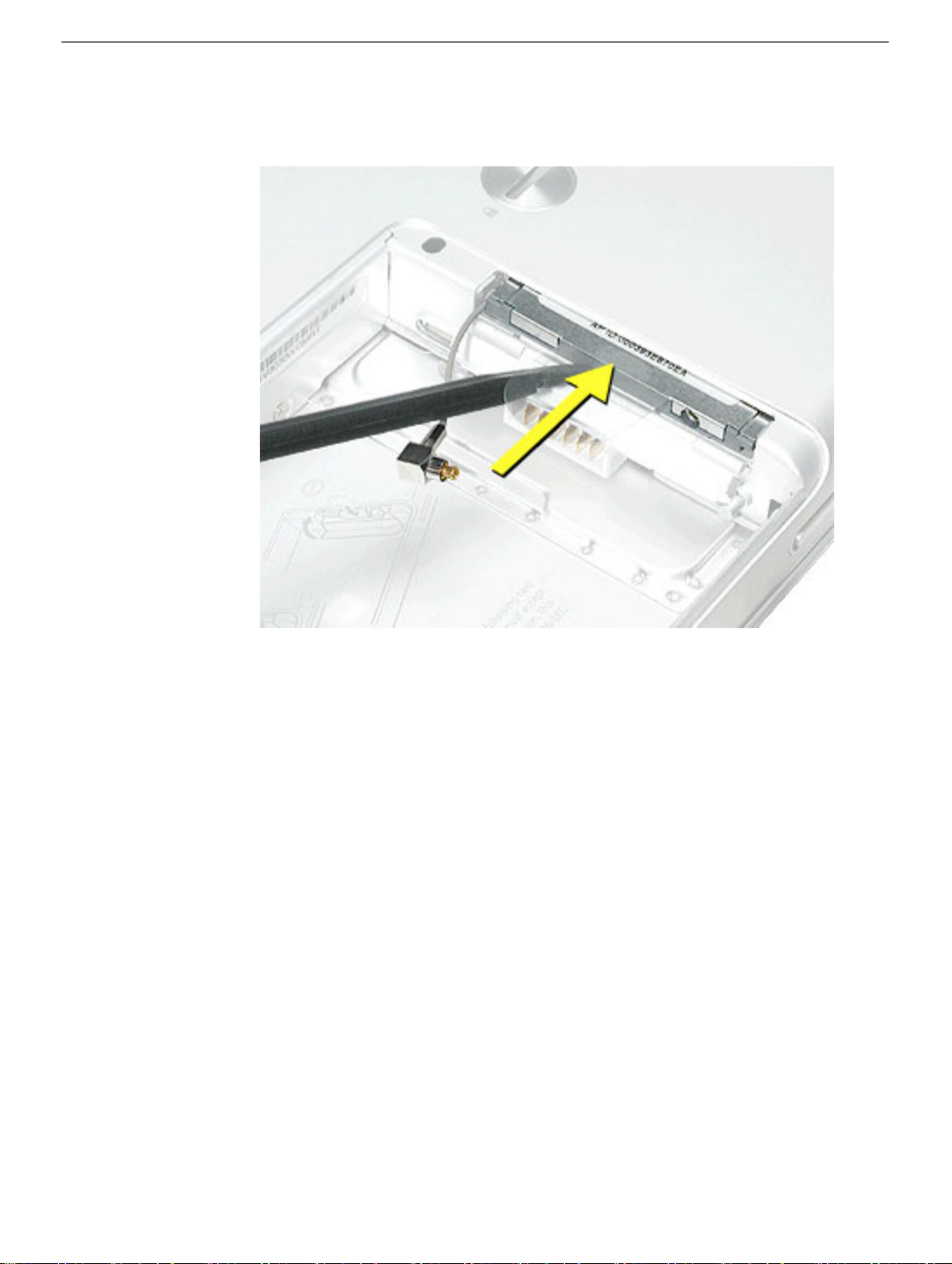
7. Slide the replacement AirPort Extreme Card with the serial number facing up into the
slot, as shown.
18 - PowerBook G4 (12-inch 1.5 GHz) Take Apart
AirPort Extreme Card
8. Connect the end of the antenna cable to the card.
9. Loop the clear plastic tab under the card so that the tab secures the antenna cable
and tucks into the slot.
Note:
The AirPort slot on the bottom case has a recessed inner slot designed for the
clear plastic tab to tuck into.
AirPort Extreme Card
PowerBook G4 (12-inch 1.5 GHz) Take Apart - 19
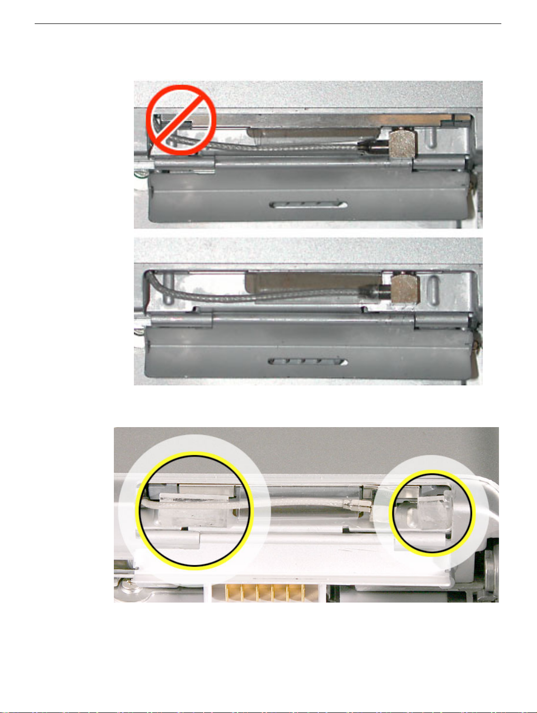
10. Make sure the card is fully inserted, as shown in the second image.
11. Paste the card stoppers inside the door.
12. Close the AirPort door, and reassemble and test the computer.
20 - PowerBook G4 (12-inch 1.5 GHz) Take Apart
AirPort Extreme Card
Keyboard
Tools
This procedure requires the following tools:
• #0 Phillips screwdriver
• Black stick (or other nonconductive nylon or plastic flat-blade tool)
Note: To organize the screws you remove from the computer, use a tray with divided
compartments (such as a plastic ice cube tray).
Part Location
Keyboard
Preliminary Steps
Before you begin, remove the following:
• Battery
• Memory door and memory card
PowerBook G4 (12-inch 1.5 GHz) Take Apart - 21
Procedure
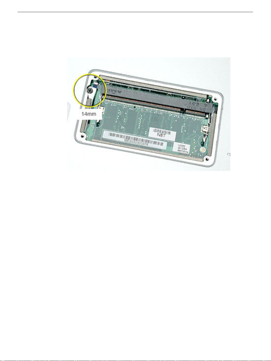
1. With the computer upside down on a soft cloth, remove the single screw from the
memory card bay.
Note: This PowerBook model differs from the previous model in that it does
not require a
small EMI shield at this screw location.
22 - PowerBook G4 (12-inch 1.5 GHz) Take Apart
Keyboard
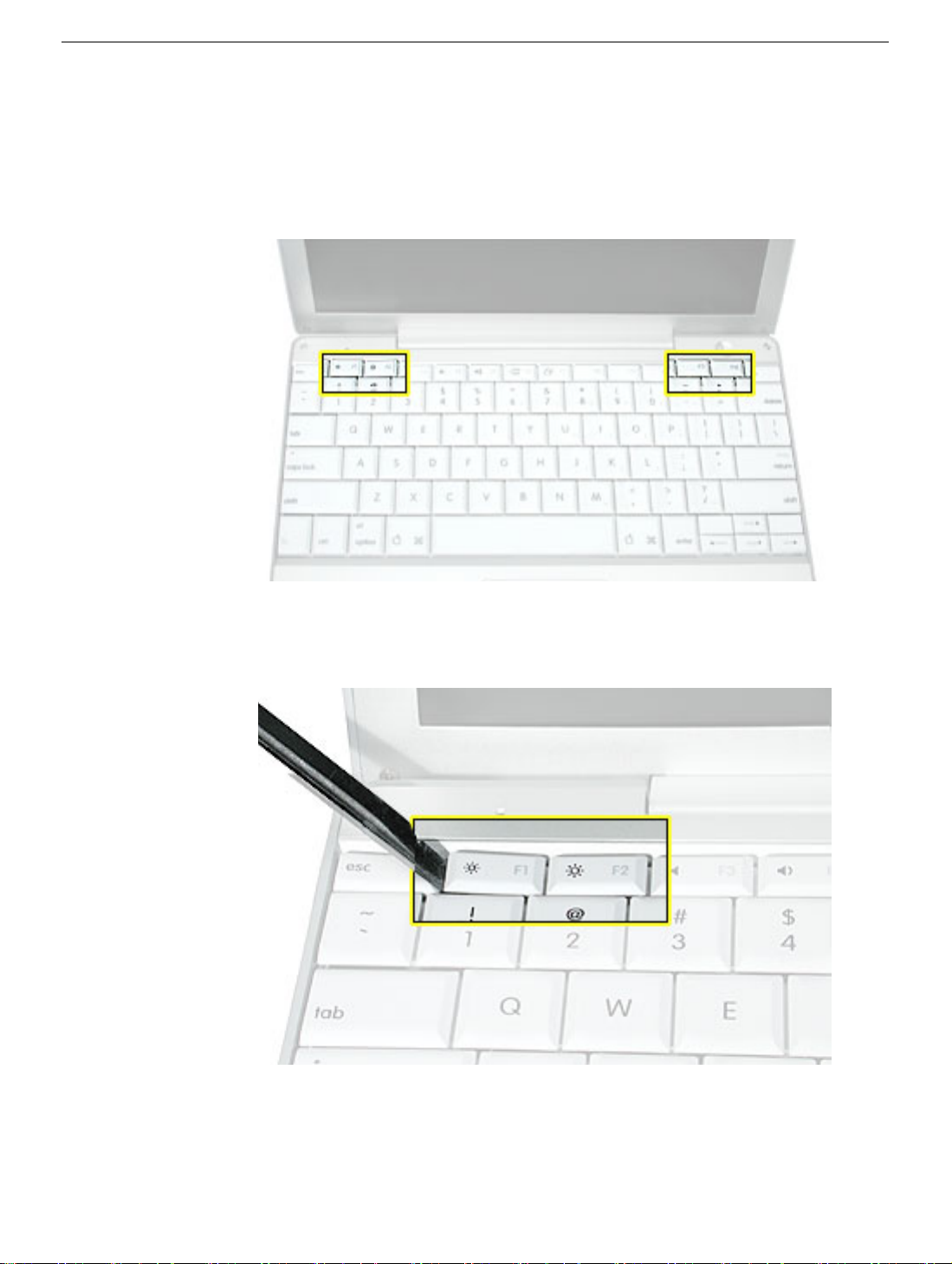
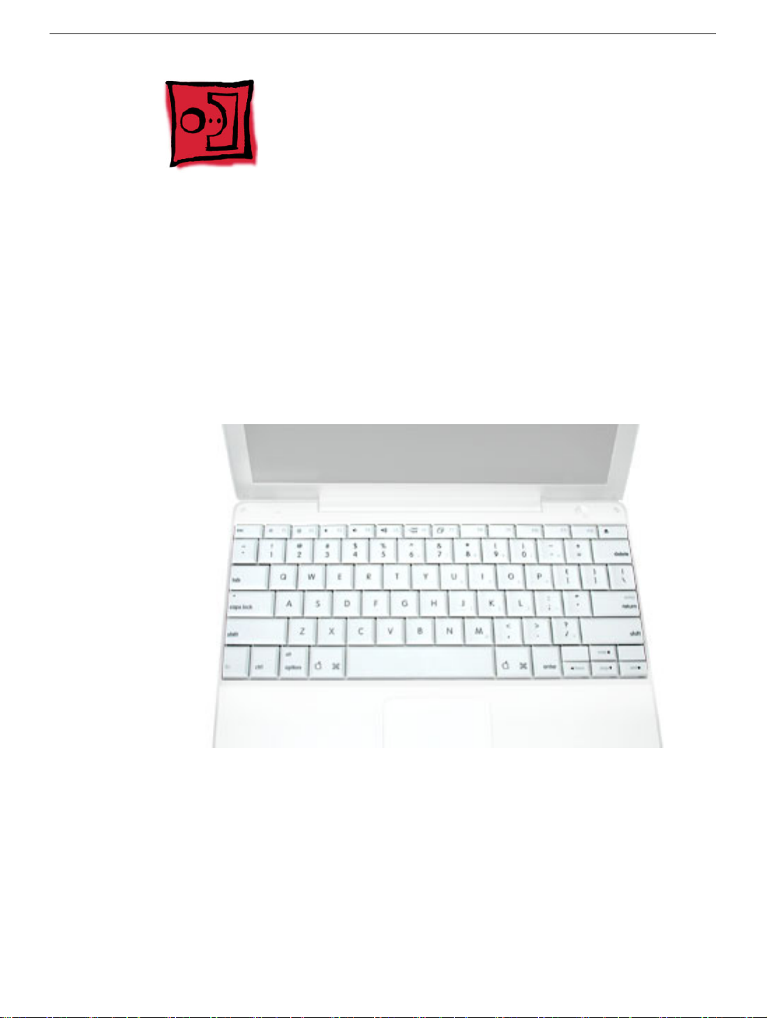
2. Open the computer, and locate the following keys:
•F1
•F2
• F11
• F12
3. Important: Using a black stick, carefully pry up each of the four keys from the left side
of each key. The keys are easily removed from the left side without damaging the
keyboard.
Keyboard
PowerBook G4 (12-inch 1.5 GHz) Take Apart - 23
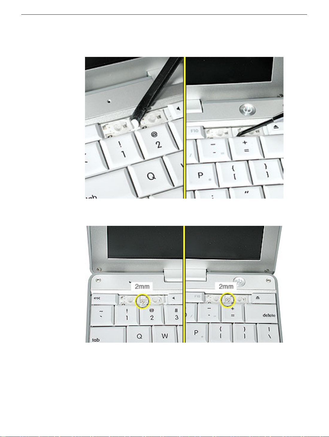
4. Use a black stick or flat-blade screwdriver to lift off the two round stickers that are
located between the two key mechanisms. Reserve the stickers for replacement.
5. Remove the screw under each of the stickers.
24 - PowerBook G4 (12-inch 1.5 GHz) Take Apart
Keyboard
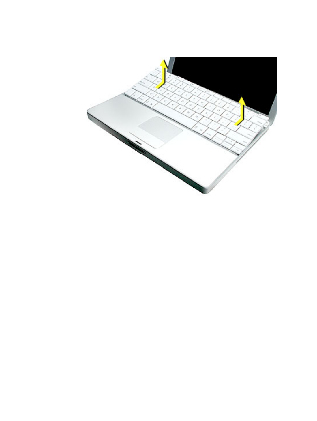
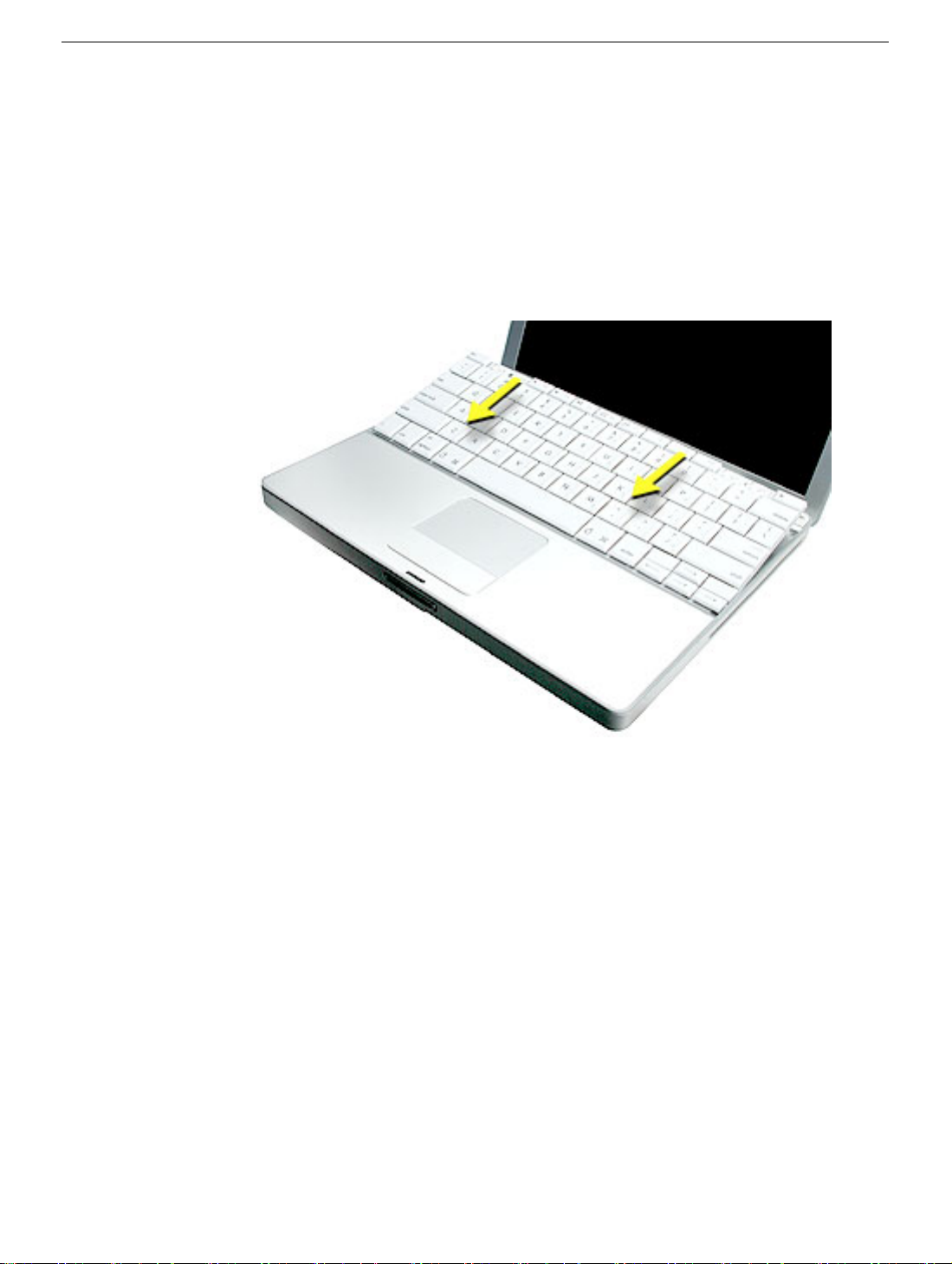
6. Lift up the top two corners of the keyboard, and move the keyboard toward the display
to clear the tabs at the bottom of the keyboard.
Keyboard
PowerBook G4 (12-inch 1.5 GHz) Take Apart - 25
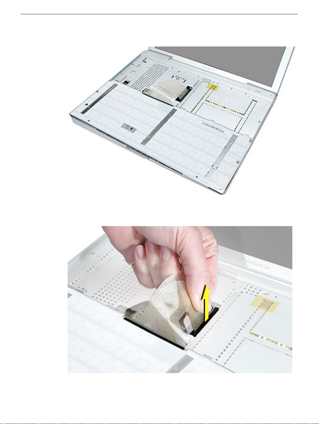
7. Flip the keyboard over and lay the keyboard flat on the trackpad.
8. Peel up the keyboard cable from its adhesive. Using a black stick, pry up the tabs at
the ends of the connector, and then pull the cable straight up to disconnect it.
26 - PowerBook G4 (12-inch 1.5 GHz) Take Apart
Keyboard
9. Install the replacement keyboard. Make sure you
• Set the tabs at the bottom of the keyboard into the slots in the top case.
• Press the keyboard into place, and install the screws and round stickers.
• Install the function keys:
– Position the key directly over the scissor mechanism.
– Press the key onto the scissor.
– Check the operation of the key.
• Close the display and install the final screw in the memory bay.
Keyboard
10. Reassemble and test the computer.
PowerBook G4 (12-inch 1.5 GHz) Take Apart - 27

Top Case
Tools
This procedure requires the following tools:
• #0 Phillips screwdriver
• Black stick (or other nonconductive nylon or plastic flat-blade tool)
• Hex 1.5 mm screwdriver
Note: To organize the screws you remove from the computer, use a tray with divided
compartments (such as a plastic ice cube tray).
Part Location
Preliminary Steps
Before you begin, remove the following:
• Battery
• Memory door and memory card
• Keyboard
28 - PowerBook G4 (12-inch 1.5 GHz) Take Apart
Top Case
 Loading...