

Page 1

Service Source
PowerBook G4 (12-inch)
January 20, 2003
© 2003 Apple Computer, Inc. All rights reserved.
Page 2

Service Source
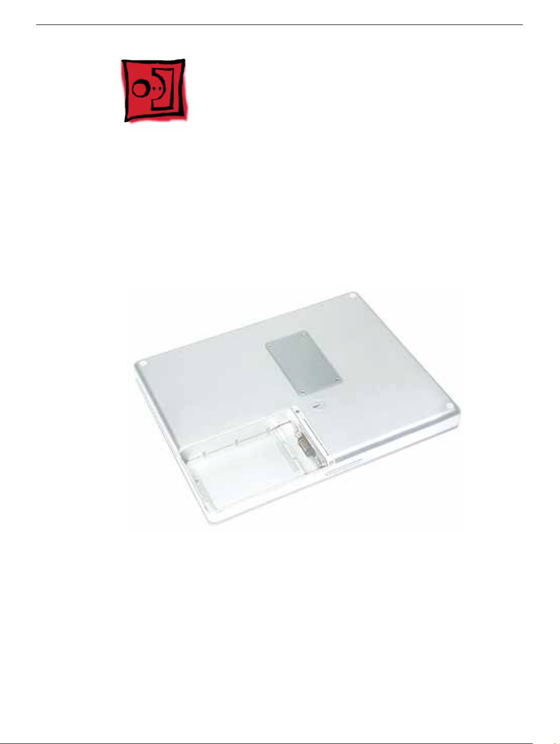
Take Apart
PowerBook G4 (12-inch)
© 2003 Apple Computer, Inc. All rights reserved.
Page 3
General Information
Overview
Some of the key features that distinguish this computer from earlier notebook models
include:
• 12-inch active-matrix display in aluminum alloy enclosure
• built-in Bluetooth
• slot load optical drive
• optional AirPort Extreme Card and Base Station
New Procedures
If you are familiar with taking apart notebook computers, you will notice some differences
with this model:
• Memory card is easily accessible from the bottom of the computer.
• Optional AirPort Extreme Card is accessed from the battery bay.
• The number and types of screws differ from earlier models.
• Additional parts that are offered for replacement include Bluetooth and the subwoofer.
General Information
PowerBook G4 (12-inch) Take Apart -
1
Page 4
Tools
Most of the tools required for taking apart this computer are the same as for earlier
notebook models; however, there are two new tools:
• 1.5 mm hex driver (small hex head screwdriver) used for the top case and the display
housing
• 4 mm socket wrench or needlenose pliers used for the DC-to-DC board
The following tools are recommended for this computer:
• Coin
• ESD wriststrap and mat
• Small soft cloth
• Black stick (or other nonconductive nylon or plastic flat-blade tool)
• #0 Phillips screwdriver (magnetized)
• #1 Phillips screwdriver (magnetized)
• Jeweler’s flat-blade screwdriver
• 1.5 mm hex driver
• 4 mm socket wrench or needlenose pliers
Important:
compartments (such as a plastic ice cube tray). If doing a complete disassembly, note the
screws removed from each location in the computer.
To organize the screws y ou remo ve from the computer, use a tra y with divided
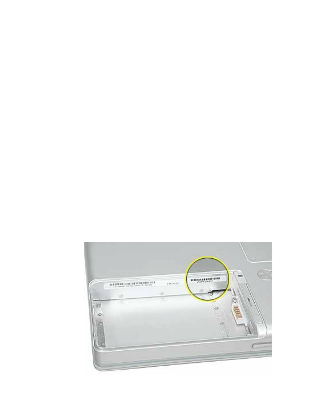
Serial Number Location
The serial number is located in the battery bay.
2 -
PowerBook G4 (12-inch) Take Apart
General Information
Page 5
Battery
Tools
This procedure requires the following tools:
• Soft cloth
• Coin
Part Location
Battery
Preliminary Steps
Warning: Always shut down the computer before opening it to avoid damaging its
internal components or causing injury. After you shut down the computer, the
internal components can be very hot. Let the computer cool down before
continuing.
PowerBook G4 (12-inch) Take Apart -
3
Page 6
Procedure
Warning:
performing this procedure.
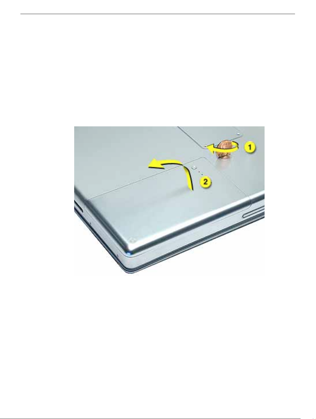
1. Shut down the computer.
2. Unplug the power adapter and phone cord.
3. Turn over the computer and place it on a soft cloth.
4. Use a coin to release the battery lock.
5. Lift the battery out of the battery bay.
If the computer has been recently operating, allow it to cool down before
6. Install the replacement battery, and reassemble and test the computer.
4 -
PowerBook G4 (12-inch) Take Apart
Battery
Page 7
Memory Door and Memory Card
Tools
This procedure requires the following tools:
• Soft cloth
• #0 Phillips screwdriver
• Black stick (or other nonconductive nylon or plastic flat-blade tool)
Part Location
Preliminary Steps
Before you begin, remove the battery.
Procedure
Warning:
performing this procedure.
Memory Door and Memory Card
If the computer has been recently operating, allow it to cool down before
PowerBook G4 (12-inch) Take Apart -
5
Page 8
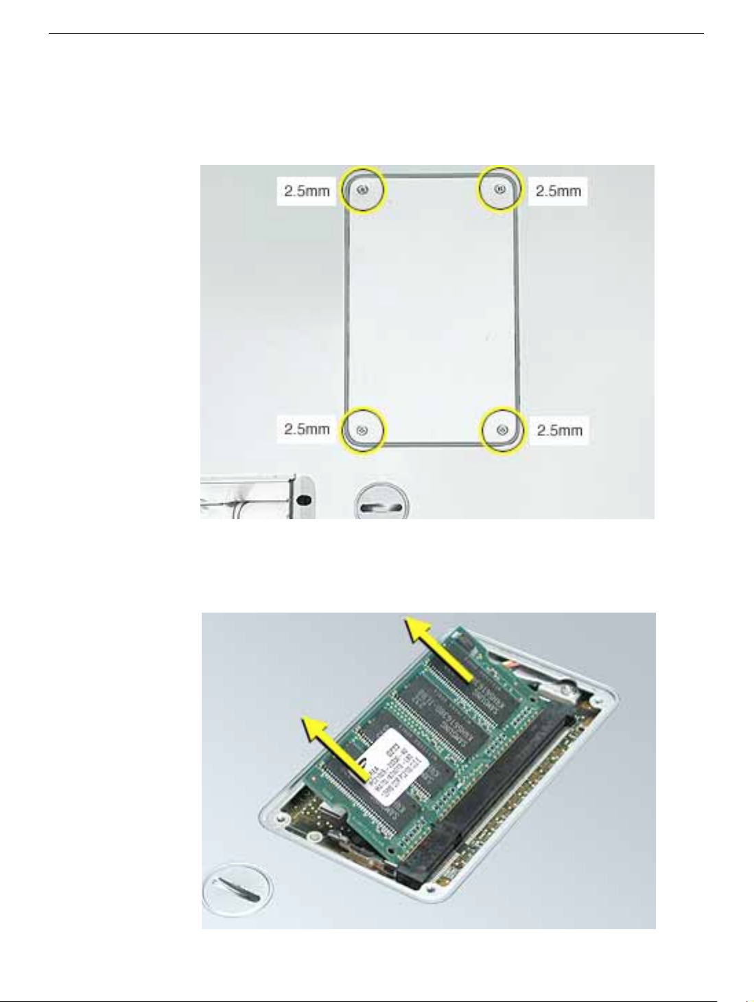
1. Place the computer upside down on a soft cloth.
2. Remove the four identical screws from the memory door.
3. Use a black stick to lift off the memory door.
4. If a memory card is already installed, release it by spreading apart the tabs in the
expansion slot from the notches in the card. Allow the card to pop up slightly, and pull
it out of the memory slot.
6 -
PowerBook G4 (12-inch) Take Apart
Memory Door and Memory Card
Page 9
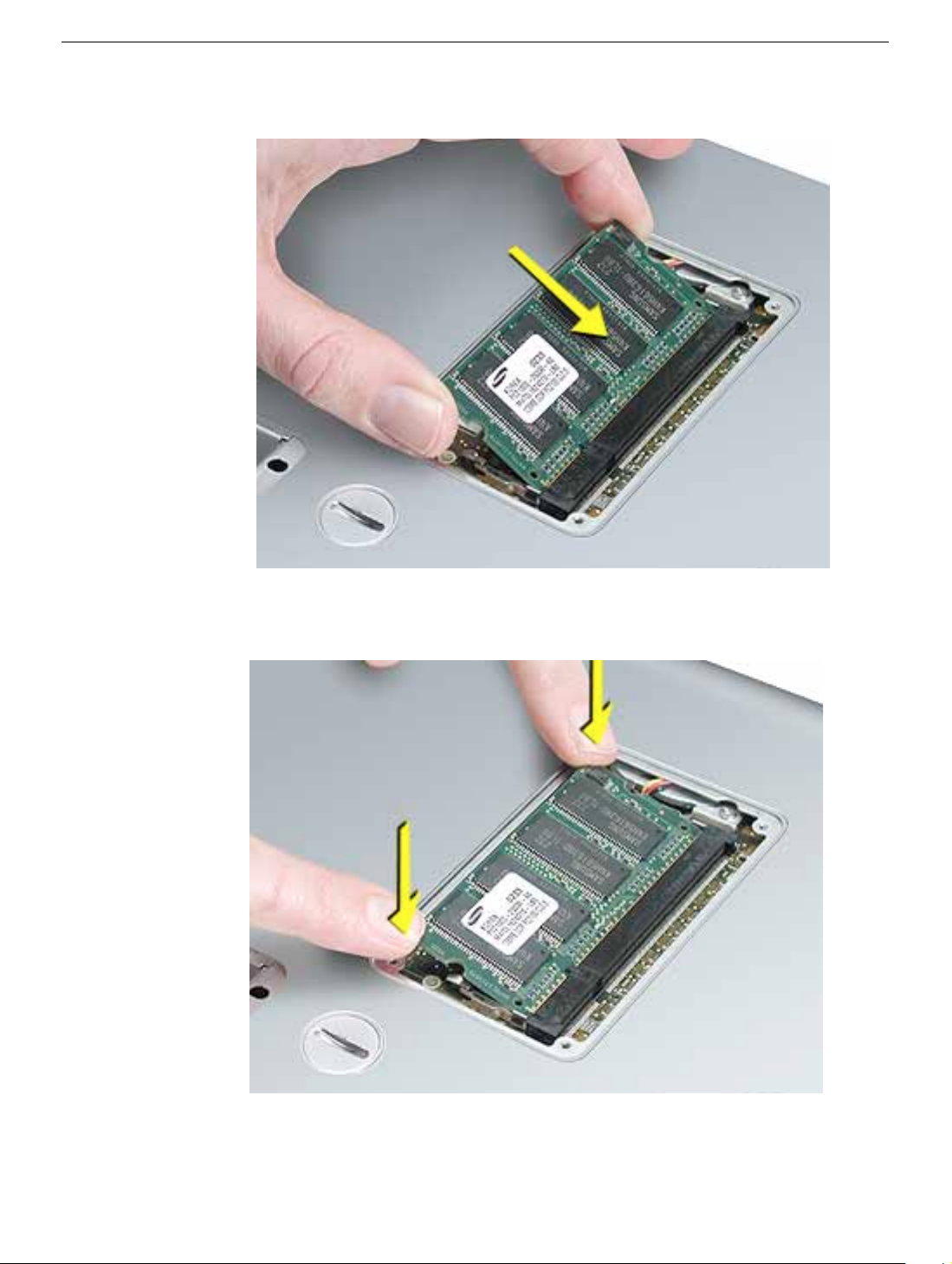
5. Insert the replacement memory card into the expansion slot at a 30-degree angle.
6. Make sure the memory card is fully inserted. Check that the notches in the card clear
the tabs as you press down on the sides of the card to lock it into place.
7. Install the memory door back onto the bottom case, and reassemble and test the
computer.
Memory Door and Memory Card
PowerBook G4 (12-inch) Take Apart -
7
Page 10
AirPort Extreme Card
Tools
This procedure requires the following tools:
• Black stick (or other nonconductive nylon or plastic flat-blade tool)
Part Location
Preliminary Steps
Before you begin, remove the battery.
8 -
PowerBook G4 (12-inch) Take Apart
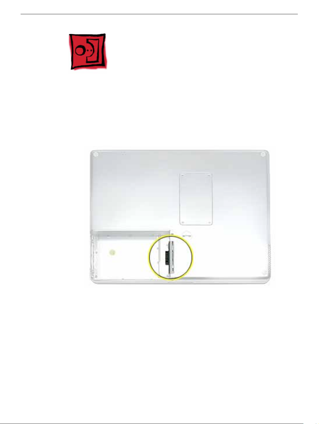
AirPort Extreme Card
Page 11
Procedure
Warning:
performing this procedure.
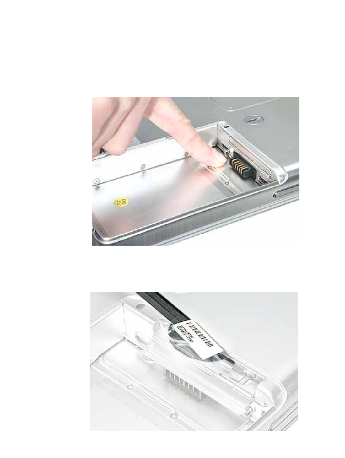
1. Touch a metal surface inside the battery bay to discharge static electricity built up on
If the computer has been recently operating, allow it to cool down before
your body.
2. Open the door to the AirPort slot.
3. If an optional AirPort Extreme Card is already installed, use a black stic k to un-loop the
pull tab.
AirPort Extreme Card
PowerBook G4 (12-inch) Take Apart -
9
Page 12
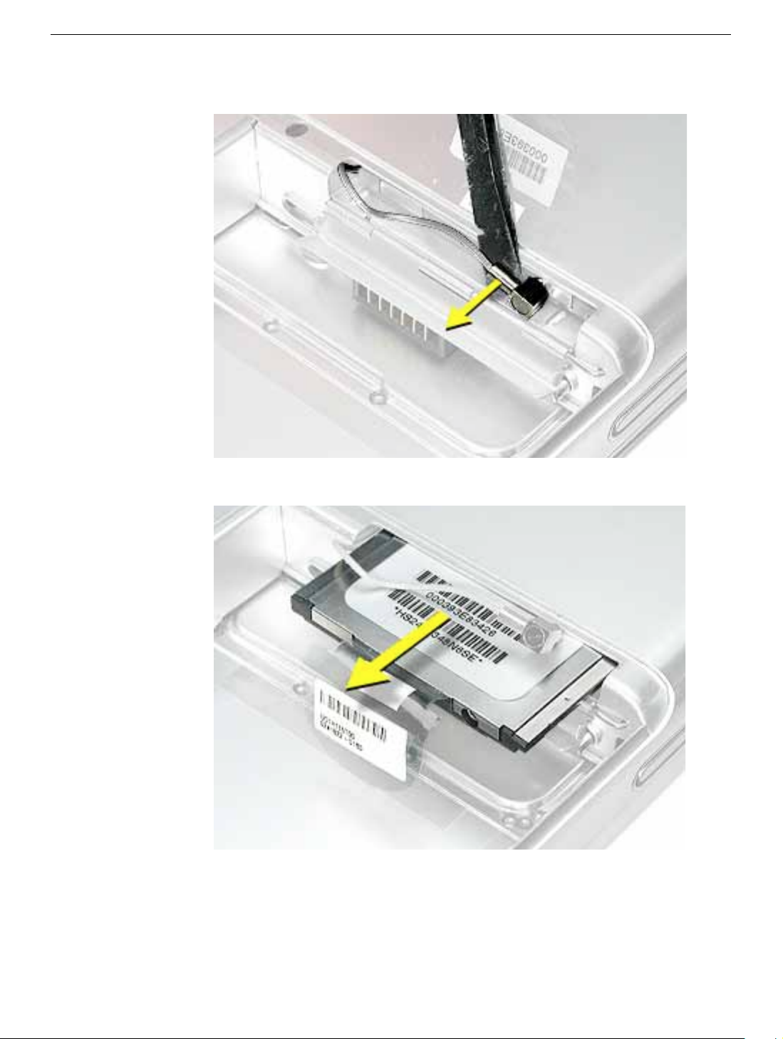
4. Gently disconnect the AirPort antenna cable.
5. Use the pull tab to pull out the card.
10 -
PowerBook G4 (12-inch) Take Apart
AirPort Extreme Card
Page 13
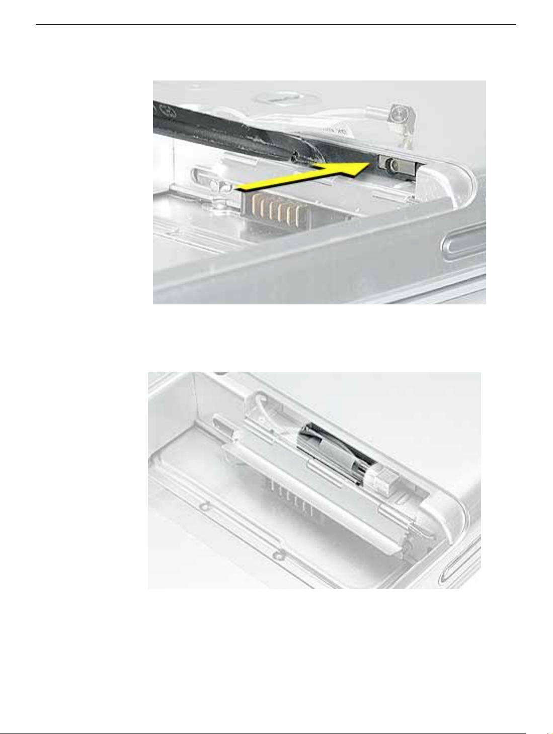
6. Slide the replacement AirPort Extreme Card into the slot, as shown.
7. Connect the end of the antenna cable to the card.
8. Loop the clear plastic tab over and under the card so that the tab secures the antenna
cable and tucks into the slot. Close the AirPort door.
9. Reassemble and test the computer.
AirPort Extreme Card
PowerBook G4 (12-inch) Take Apart -
11
Page 14
Keyboard
Tools
This procedure requires the following tools:
• #0 Phillips screwdriver
• Black stick (or other nonconductive nylon or plastic flat-blade tool)
Note:
To organize the screws you remove from the computer, use a tray with divided
compartments (such as a plastic ice cube tray).
Part Location
Preliminary Steps
Before you begin, remove the following:
• Battery
• Memory door and memory card
12 -
PowerBook G4 (12-inch) Take Apart
Keyboard
Page 15
Procedure
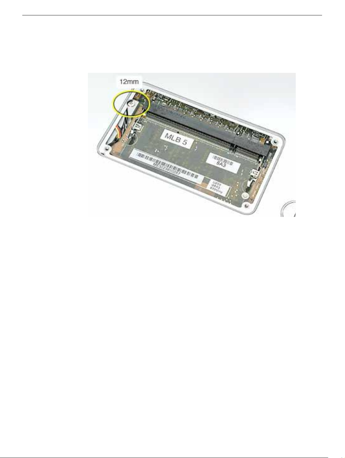
1. With the computer upside down on a soft cloth, remove the single screw from the
memory card bay.
Keyboard
PowerBook G4 (12-inch) Take Apart -
13
Page 16
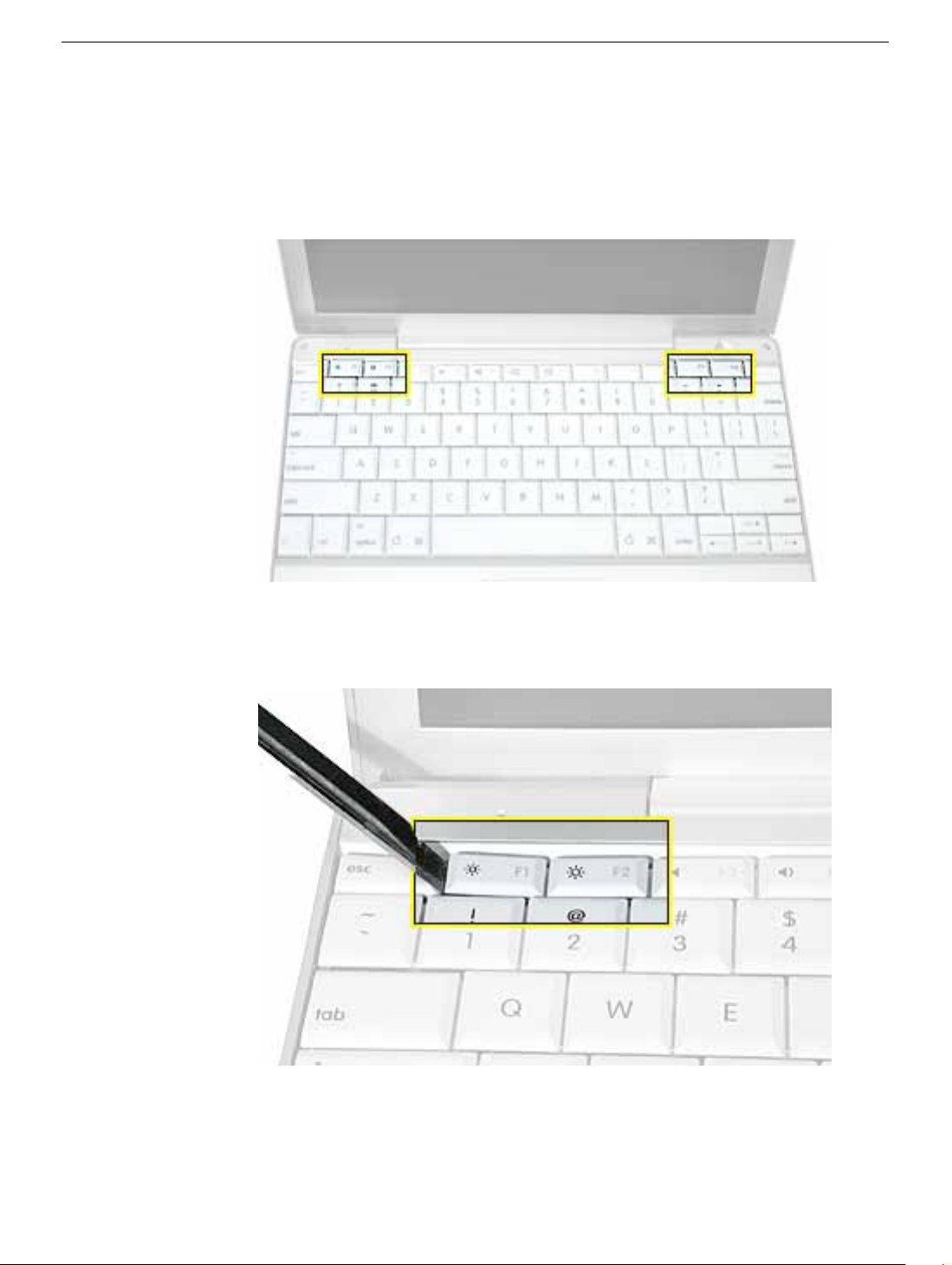
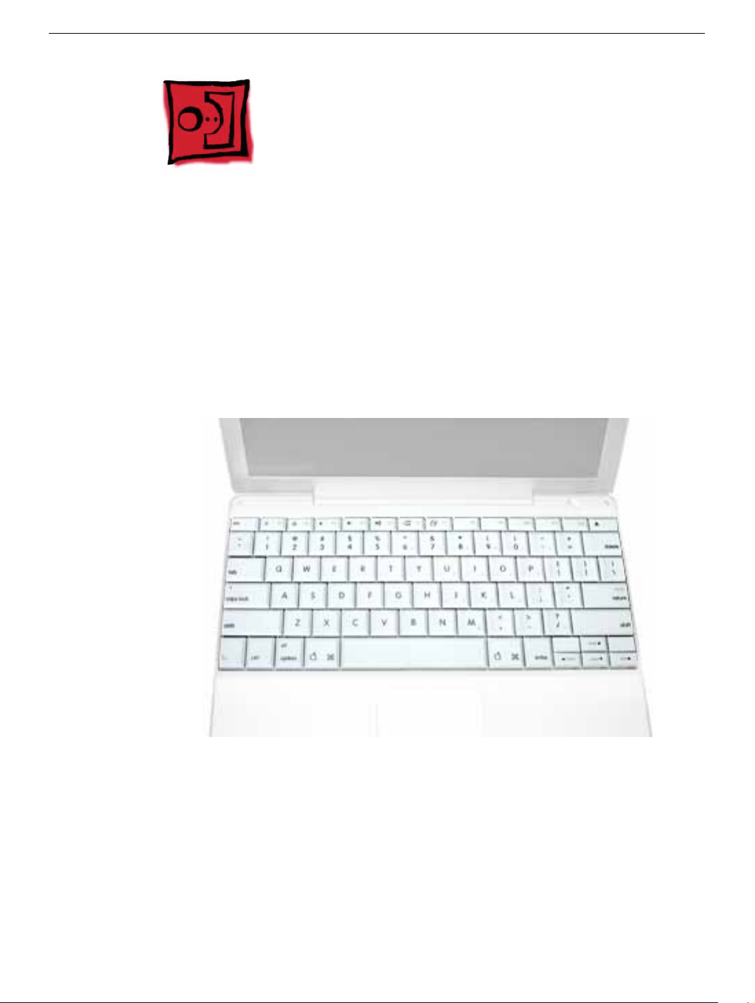
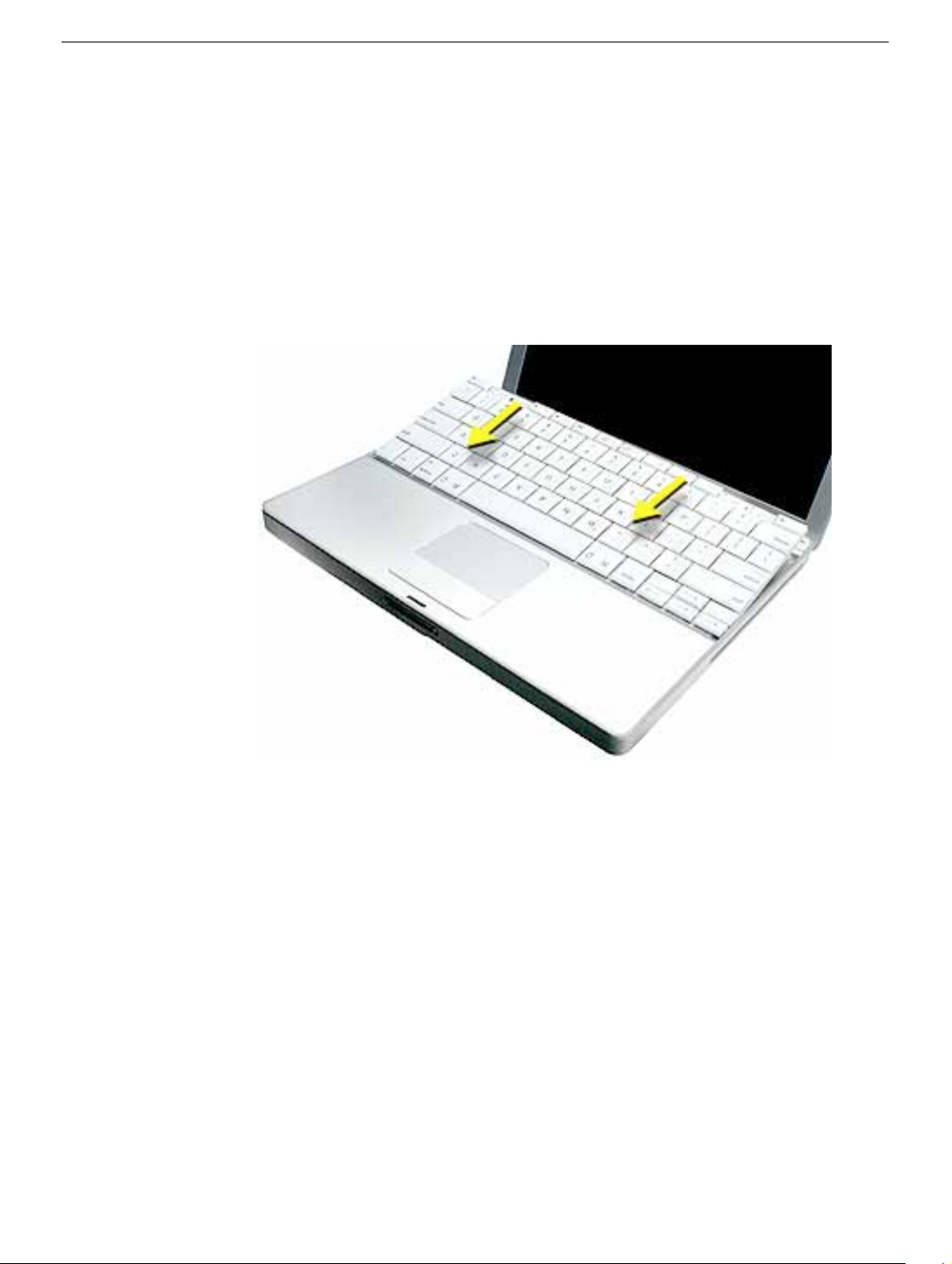
2. Open the computer, and locate the following keys:
•F1
•F2
• F11
• F12
3.
Important:
of each key. The keys are easily removed from the left side without damaging the
keyboard.
Using a black stick, carefully pry up each of the four k eys from the left side
14 -
PowerBook G4 (12-inch) Take Apart
Keyboard
Page 17
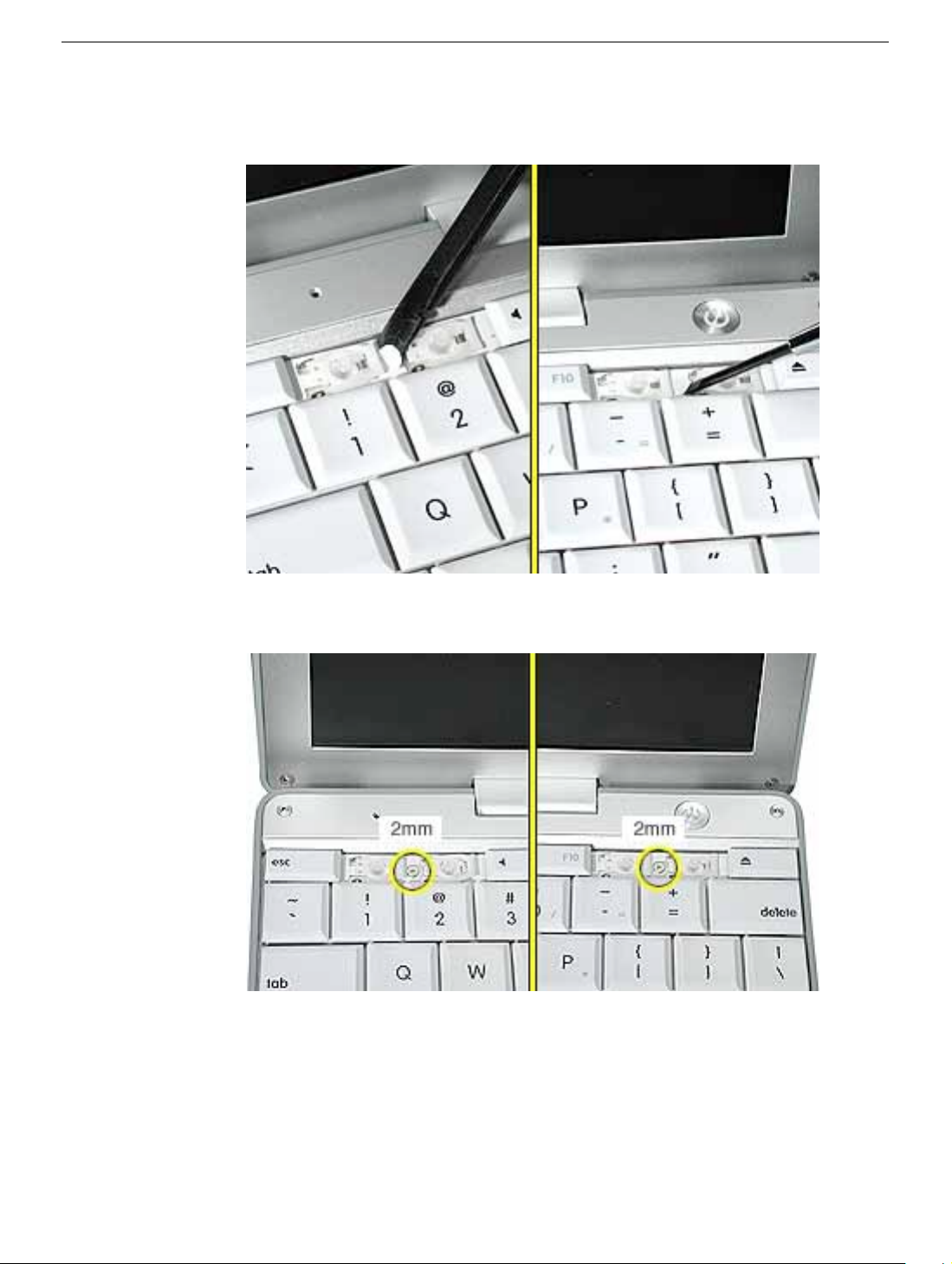
4. Use a black stick or flat-blade screwdriver to lift off the two round stickers that are
located between the two key mechanisms. Reserve the stickers for replacement.
5. Remove the screw under each of the stickers.
Keyboard
PowerBook G4 (12-inch) Take Apart -
15
Page 18
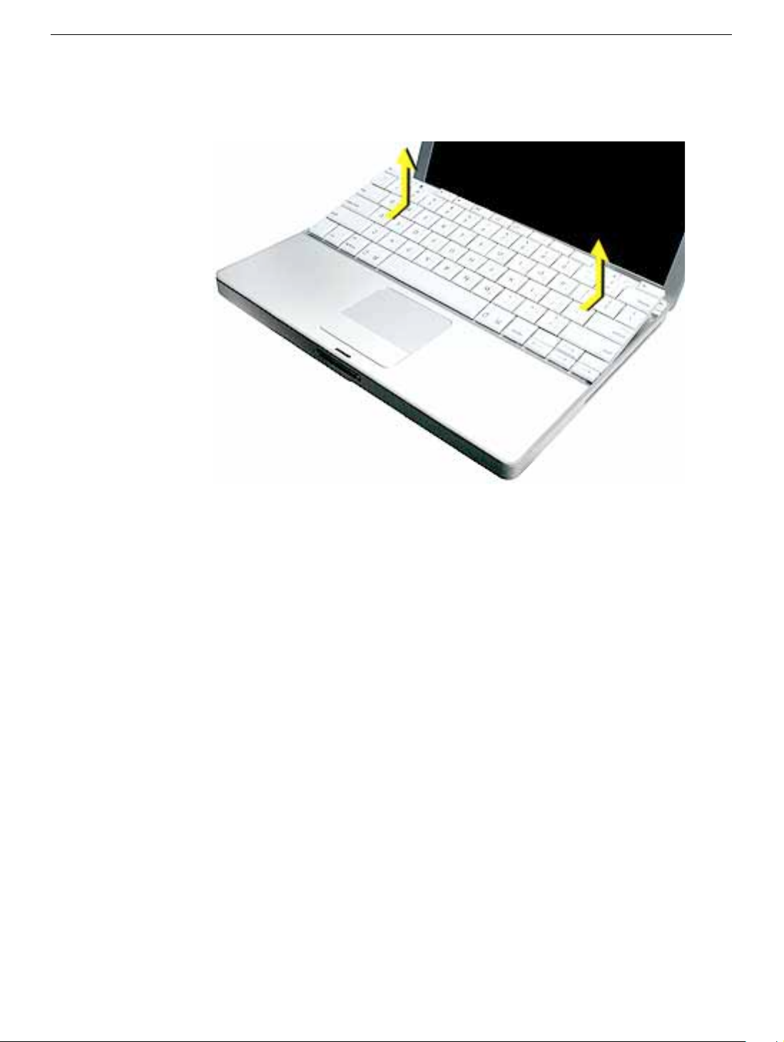
6. Lift up the top two corners of the keyboard, and move the k e yboard to w ard the displa y
to clear the tabs at the bottom of the keyboard.
16 -
PowerBook G4 (12-inch) Take Apart
Keyboard
Page 19
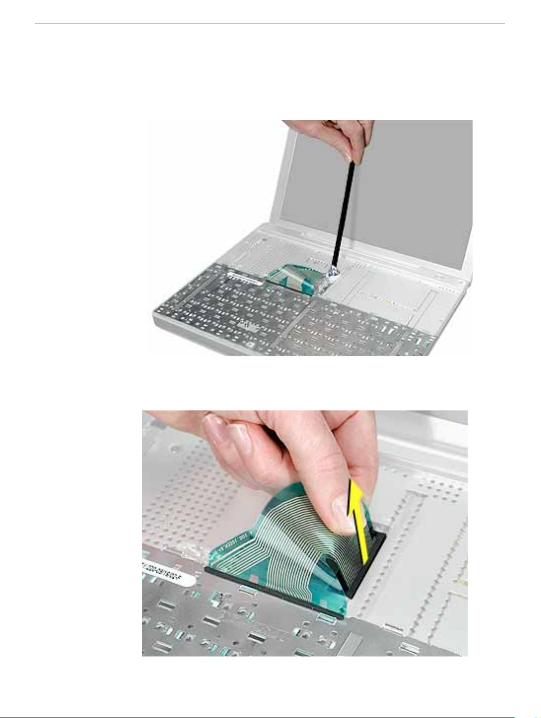
7. Flip the keyboard over and lay the keyboard flat on the trackpad.
8. Use a black stick to carefully remove the aluminum tape that covers the keyboard
connector. You will need to reuse the tape when reassembling the computer.
9. Peel up the keyboard cable from its adhesive. Using a black stick, pry up the tabs at
the ends of the connector, and then pull the cable straight up to disconnect it.
Keyboard
PowerBook G4 (12-inch) Take Apart -
17
Page 20
10. Install the replacement keyboard. Make sure you
• Install the foil tape in the recessed area over the keyboard connector.
• Set the tabs at the bottom of the keyboard into the slots in the top case.
• Press the keyboard into place, and install the screws and round stickers.
• Install the function keys:
– Position the key directly over the scissor mechanism.
– Press the key onto the scissor.
– Check the operation of the key.
• Close the display and install the final screw in the memory bay.
11. Reassemble and test the computer.
18 -
PowerBook G4 (12-inch) Take Apart
Keyboard
Page 21
Top Case
Tools
This procedure requires the following tools:
• #0 Phillips screwdriver
• Black stick (or other nonconductive nylon or plastic flat-blade tool)
• Hex 1.5 mm screwdriver
Note:
To organize the screws you remove from the computer, use a tray with divided
compartments (such as a plastic ice cube tray).
Part Location
Top Case
Preliminary Steps
Before you begin, remove the following:
• Battery
• Memory door and memory card
• Keyboard
PowerBook G4 (12-inch) Take Apart -
19
Page 22
Procedure
1.
Warning:
angle. Be careful not to strip the screws.
Note:
screws. You might want to cover part of the housing with a soft cloth as you
remove screws.
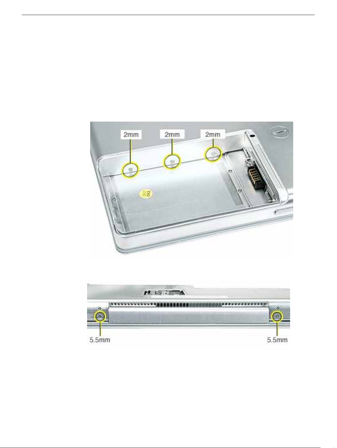
With the computer upside down on a soft cloth, remove the three screws from
the bottom case at the battery bay.
The screws in the battery bay require holding the screwdriver at an
Avoid scratching the external housing by using care when removing the
2. Remove the screws near the display hinge.
20 -
PowerBook G4 (12-inch) Take Apart
Top Case
Page 23
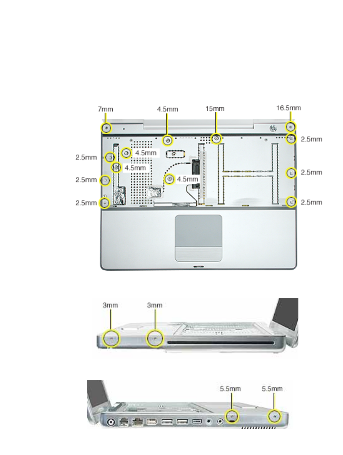
3. Open the display, and with the computer upright, remove the following 13 screws from
the top case:
• one Hex, 16.5 mm long screw at upper right corner near power button
• one Hex, 7 mm long screw at upper left corner near microphone
• one #0 Phillips, 15 mm long screw in keyboard well
• four #0 Phillips, 4.5 mm long screws in keyboard well
• six #0 Phillips, 2.5 mm long screws in keyboard well
Top Case
4. Remove two screws from the front right side of the top case.
5. Remove two screws from the front left side of the top case.
PowerBook G4 (12-inch) Take Apart -
21
Page 24
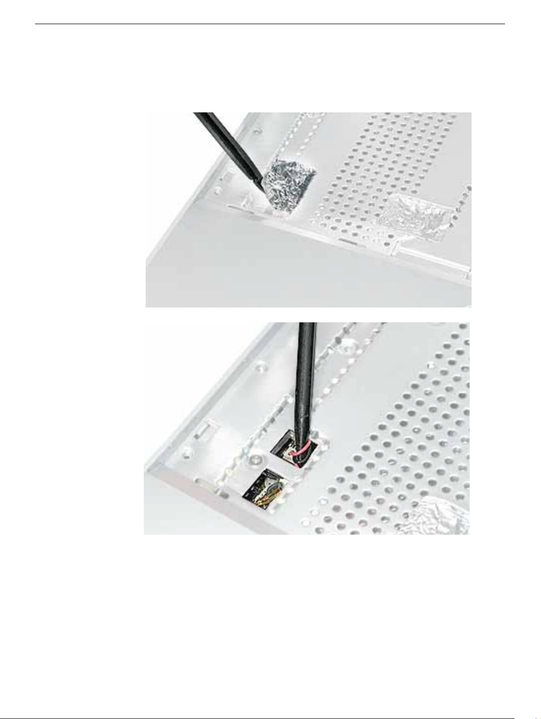
6. Carefully remove the f oil tape from the keyboard w ell that cov ers the microphone cable
and power cable. You will need to reuse the tape when reassembling the computer.
7. Use a black stick in the small openings to disconnect the two cables.
22 -
PowerBook G4 (12-inch) Take Apart
Top Case
Page 25
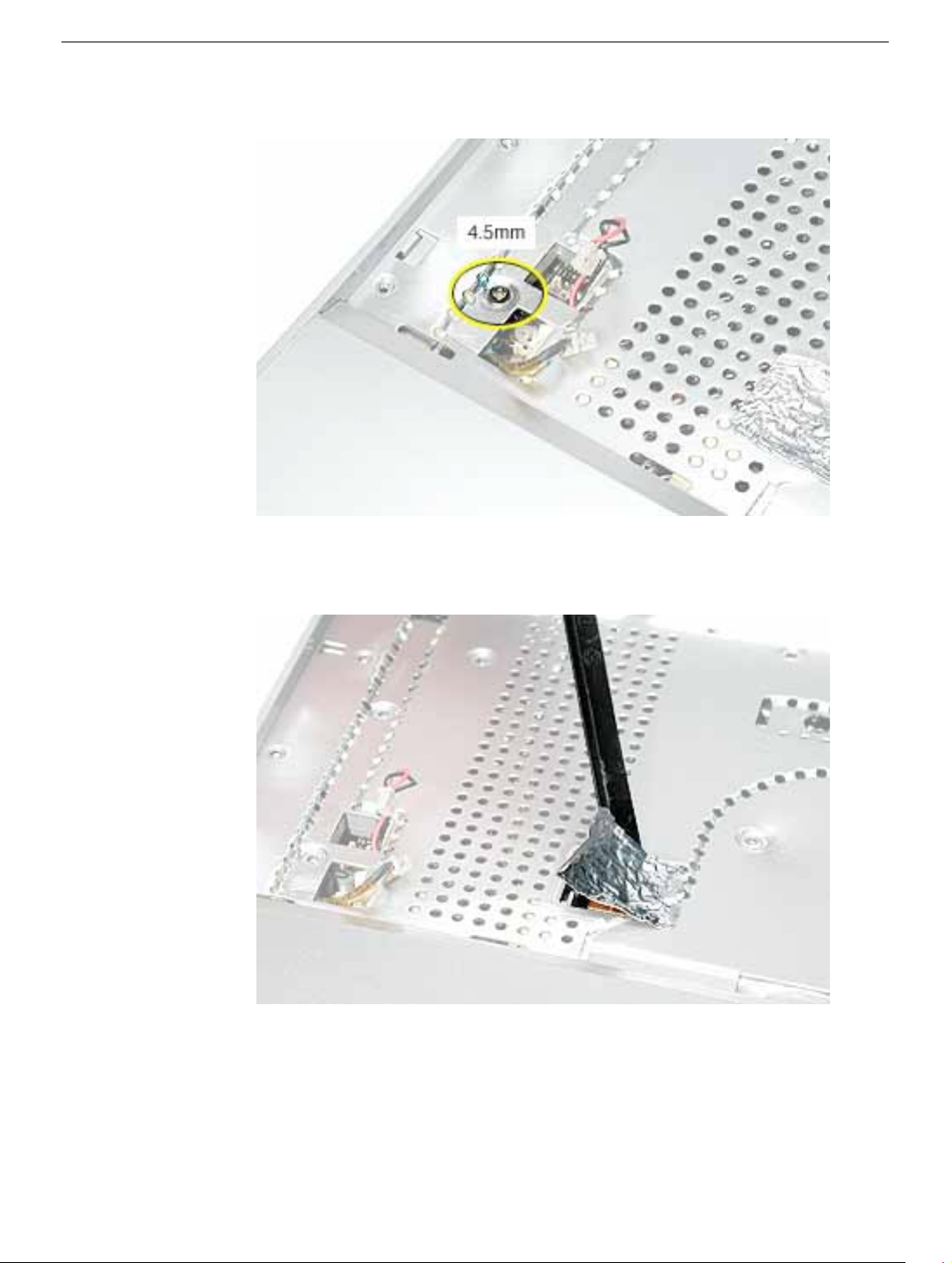
8. Remove the screw near the cables.
9. Carefully remove the foil tape over the trackpad cable. You will need to reuse the tape
when reassembling the computer.
Top Case
PowerBook G4 (12-inch) Take Apart -
23
Page 26
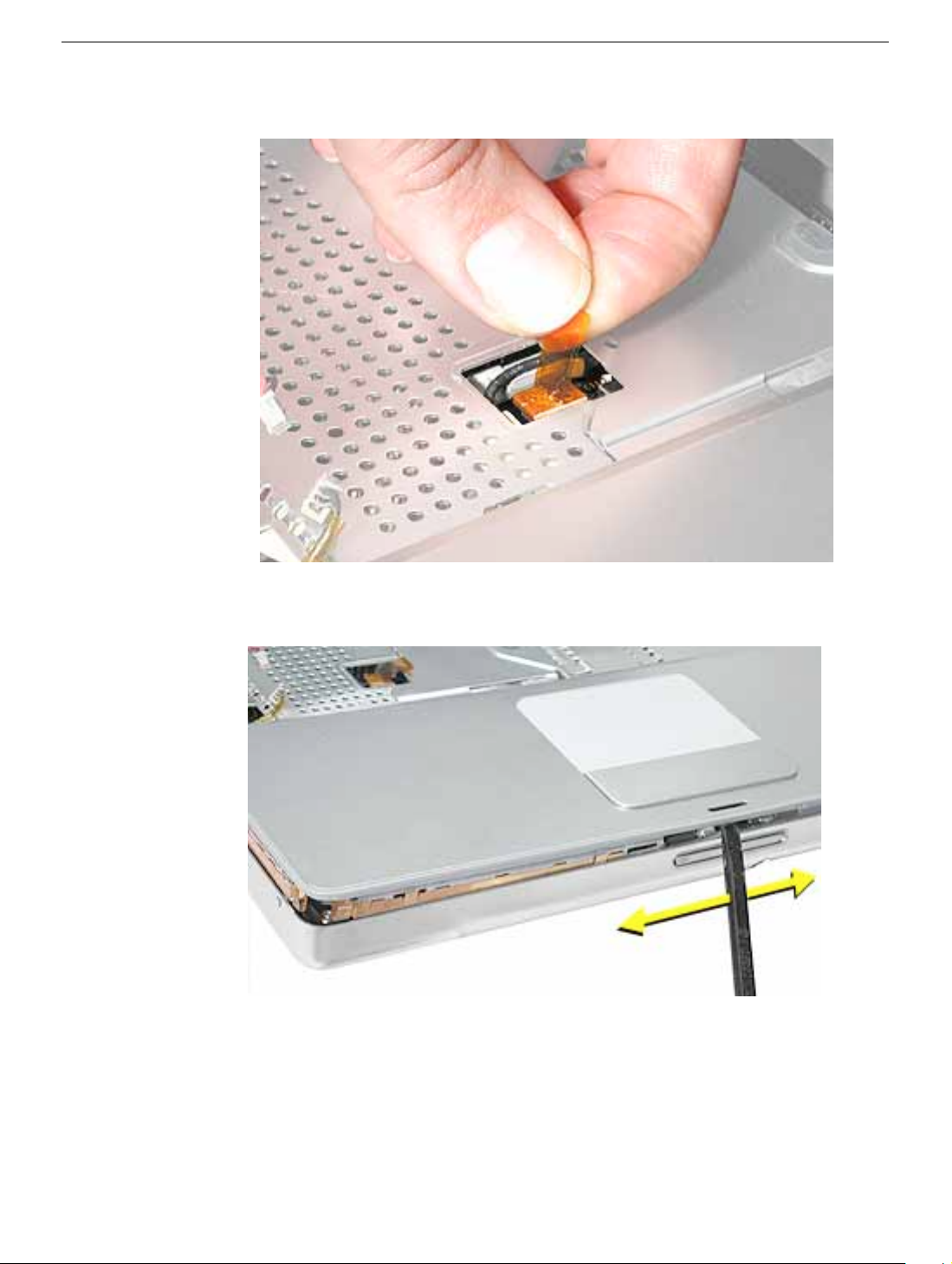
10. Use the pull tab to release the trackpad cable.
11. Use a black stick running along the edge of the top case to lift up the top case from the
bottom case. Use equal pressure at the front, left, and right corners.
24 -
PowerBook G4 (12-inch) Take Apart
Top Case
Page 27
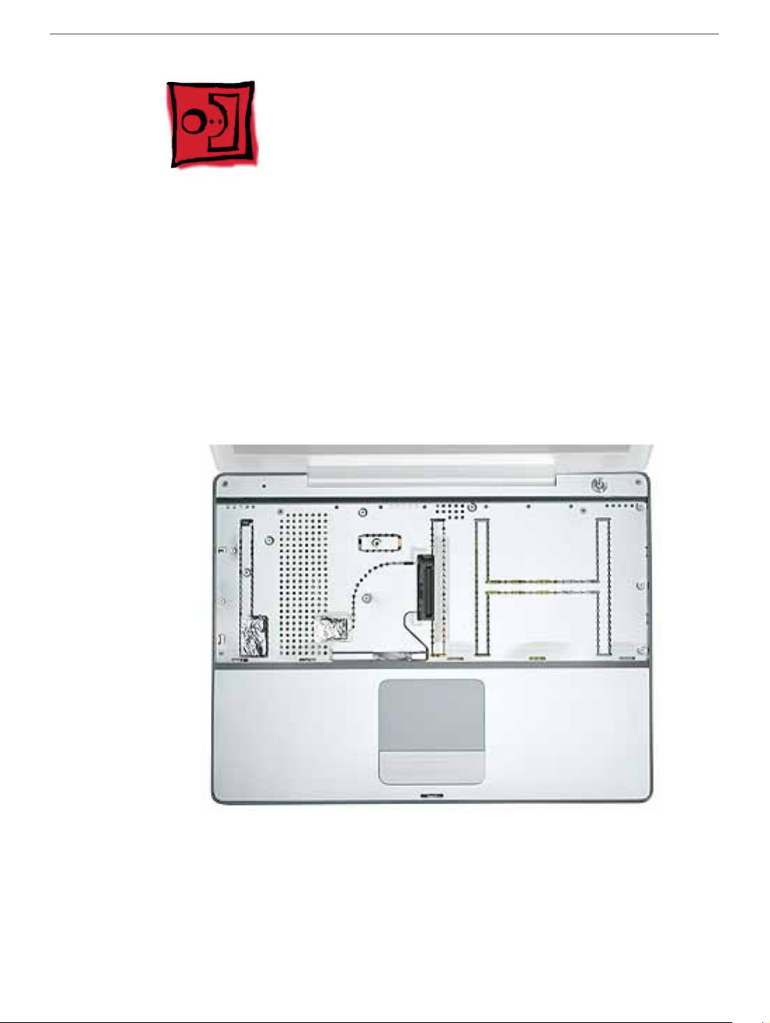
12. The top case includes the following:
• Microphone cable
• Trackpad and trackpad cable
• Power button and cable
• Tape
• Welded EMI strips
Top Case
PowerBook G4 (12-inch) Take Apart -
25
Page 28
13. Before installing a replacement top case, check the cable routing of the
• Microphone cable
• Trackpad cable
• Power button cable
Make sure the cables are routed correctly and cannot be pinched when
installing the top case.
14. Install the replacement top case, and reassemble and test the computer.
26 -
PowerBook G4 (12-inch) Take Apart
Top Case
Page 29
Reed Switch Board and Cable
Tools
This procedure requires the following tools:
• Phillips #0 screwdriver
• Black stick (or other nonconductive nylon or plastic flat-blade tool)
Part Location
Preliminary Steps
Before you begin, remove the following:
• Battery
• Memory door and memory card
• Keyboard
• Top case
Reed Switch Board and Cable
PowerBook G4 (12-inch) Take Apart -
27
Page 30
Procedure
1. Remove the screw from the reed switch board.
Warning:
longer screw could scratch the optical media.
2. Tilt the board up and away from the tab at the battery area.
3. Lift up the tape from the corner of the optical drive, and disconnect the 3-pin connector
from CN4 at the DC-to-DC board.
When replacing the board, make sure you use the same screw. A
4. Install the replacement reed switch board and cable, and reassemble and test the
computer.
28 -
PowerBook G4 (12-inch) Take Apart
Reed Switch Board and Cable
Page 31

Hard Drive
Tools
This procedure requires the following tools:
• #0 Phillips screwdriver
• Black stick (or other nonconductive nylon or plastic flat-blade tool)
Note:
To organize the screws you remove from the computer, use a tray with divided
compartments (such as a plastic ice cube tray).
Part Location
Hard Drive
Preliminary Steps
Before you begin, remove the following:
• Battery
• Memory door and memory card
PowerBook G4 (12-inch) Take Apart -
29
Page 32

• Keyboard
• Top case
Procedure
1. Disconnect the hard drive flex cable.
2. Remove two screws from the hard drive bracket.
30 -
PowerBook G4 (12-inch) Take Apart
Hard Drive
Page 33

3. Use the flex cable to lift up the hard drive, bracket, and cable from the computer
housing.
4. Turn over the hard drive and remove the two screws from the underside of the brack et.
Hard Drive
PowerBook G4 (12-inch) Take Apart -
31
Page 34

5. Peel up the flex cable from its double-sided tape.
6. Use a black stick to pry the flex cab le connector up slightly on each side , and then pull
it straight off the drive. Be careful not to bend any pins.
7. Remove the two screws and grommets from the opposite side of the drive.
8.
Replacement Note:
flange of the hard drive bracket fits over the small post on the computer frame.
9. Install the replacement hard drive, and reassemble and test the computer.
32 -
PowerBook G4 (12-inch) Take Apart
When installing the replacement drive, make sure the center
Hard Drive
Page 35

DC-to-DC Board
Tools
This procedure requires the following tools:
• #0 Phillips screwdriver (magnetized preferred)
• Black stick (or other nonconductive nylon or plastic flat-blade tool)
• 4 mm socket wrench or needlenose pliers
Note:
To organize the screws you remove from the computer, use a tray with divided
compartments (such as a plastic ice cube tray).
Part Location
DC-to-DC Board
Preliminary Steps
Before you begin, remove the following:
• Battery
PowerBook G4 (12-inch) Take Apart -
33
Page 36

• Memory door and memory card
• Keyboard
• Top case
• Hard drive
Procedure
1. Remove the three screws from the DC-to-DC board.
Note: When removing the 3 mm-long screw, the magnetic latch might draw the
screw toward it.
2. Remove the two screws at the battery connector.
34 - PowerBook G4 (12-inch) Take Apart
DC-to-DC Board
Page 37

3. Lift off the EMI strip from the battery connector. Be sure to replace it when installing
the replacement DC-to-DC board.
4. Use a black stick to tilt up the board from the logic board, and lift the opposite end of
the board to remove it from the computer housing.
Warning: To avoid bending pins, lift the board evenly at both ends.
5. Install the replacement DC-to-DC board, and reassemble and test the computer.
DC-to-DC Board
PowerBook G4 (12-inch) Take Apart - 35
Page 38

Modem
Tools
This procedure requires the following tools:
• #0 Phillips screwdriver
• Black stick (or other nonconductive nylon or plastic flat-blade tool)
Part Location
Preliminary Steps
Before you begin, remove the following:
• Battery
• Memory door and memory card
• Keyboard
• Top case
36 - PowerBook G4 (12-inch) Take Apart
Modem
Page 39

Procedure
1. Remove the two screws from the modem board.
2. Use a black stick to tilt up the modem and disconnect it from the logic board.
Modem
PowerBook G4 (12-inch) Take Apart - 37
Page 40

3. At the other end of the modem, disconnect the modem cable from the connector.
Replacement Note: When placing the replacement modem on the logic board, be sure to
align the board over the standoffs and connector on the logic board.
4. Install the replacement modem, and reassemble and test the computer.
38 - PowerBook G4 (12-inch) Take Apart
Modem
Page 41

Heatsink and Fan Assembly
Tools
This procedure requires the following tools:
• #0 Phillips screwdriver
• #1 Phillips screwdriver
• Black stick (or other nonconductive nylon or plastic flat-blade tool)
Note: To organize the screws you remove from the computer, use a tray with divided
compartments (such as a plastic ice cube tray).
Part Location
Preliminary Steps
Before you begin, remove the following:
• Battery
• Memory door and memory card
• Keyboard
• Top case
• Modem
Heatsink and Fan Assembly
PowerBook G4 (12-inch) Take Apart - 39
Page 42

Procedure
1. Warning: The cone of the subwoofer, located below the heatsink and to the right of
the fan, is a sensitive device. Avoid touching the subwoofer cone as you perform this
procedure.
2. Peel up the tape if any of the following screws are covered. Remove the following
screws from the heatsink:
• Two 6 mm long #0 Phillips screws
• Two 7.5 mm long #1 Phillips screws with springs
• One 13 mm long #0 Phillips screw
• One 4.5 mm long #0 Phillips screw
40 - PowerBook G4 (12-inch) Take Apart
Heatsink and Fan Assembly
Page 43

3. Remove the tape that covers the heatsink and secures the cables in place.
4. Near the fan, peel up the tape and remove the following screws:
• One 3 mm long screw
• One 6 mm long screw
• One 13 mm long screw
5. Peel up the yellow tape, and disconnect the inverter cable that runs along the top of
the fan from the logic board.
6. Remove the transparent tape at the bottom of the fan, and disconnect the fan cable.
Replacement Note: When installing the replacement heatsink assembly, note
that the fan cable is routed beneath the computer frame.
Heatsink and Fan Assembly
PowerBook G4 (12-inch) Take Apart - 41
Page 44

7. Holding the heatsink at the crossbar, begin to lift up the heatsink assembly, being
careful where it catches on remaining tape and the chassis. Use a blac k stick to pry up
the middle right corner of the heatsink plate.
Warning: To avoid bending the heatsink, support the heatsink as it is removed.
8. Route the fan cable through the slot in the computer frame.
42 - PowerBook G4 (12-inch) Take Apart
Heatsink and Fan Assembly
Page 45

9. Note the routing of the remaining cables and the placement of tape once the heatsink
is removed.
.
10. Install the replacement heatsink and fan assembly, and reassemble and test the
computer.
Heatsink and Fan Assembly
PowerBook G4 (12-inch) Take Apart - 43
Page 46

Inner Frame
Tools
This procedure requires the following tools:
• #0 Phillips screwdriver
• Black stick (or other nonconductive nylon or plastic flat-blade tool)
Note: To organize the screws you remove from the computer, use a tray with divided
compartments (such as a plastic ice cube tray).
Part Location
Preliminary Steps
Before you begin, remove the following:
• Battery
• Memory door and memory card
• Keyboard
• Top case
44 - PowerBook G4 (12-inch) Take Apart
Inner Frame
Page 47

• Reed switch
• Hard drive
• DC-to-DC board
• Modem
• Heatsink with fan
Procedure
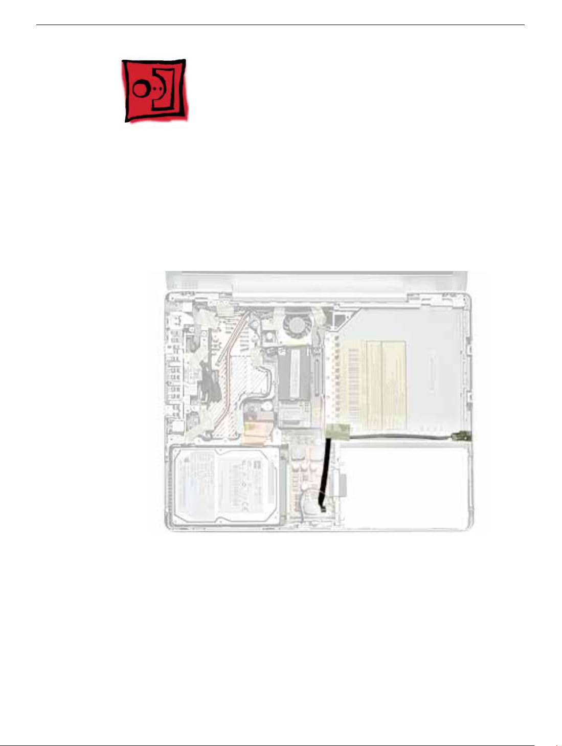
1. Note the cable routing and placement of tape before disconnecting cables.
Replacement Note: Reserve the tape for securing cables after the frame
replacement.
Inner Frame
PowerBook G4 (12-inch) Take Apart - 45
Page 48

2. Warning: The subwoofer cone, located below the right corner of the frame, is a
sensitive device. Avoid touching the cone as you perform this procedure.
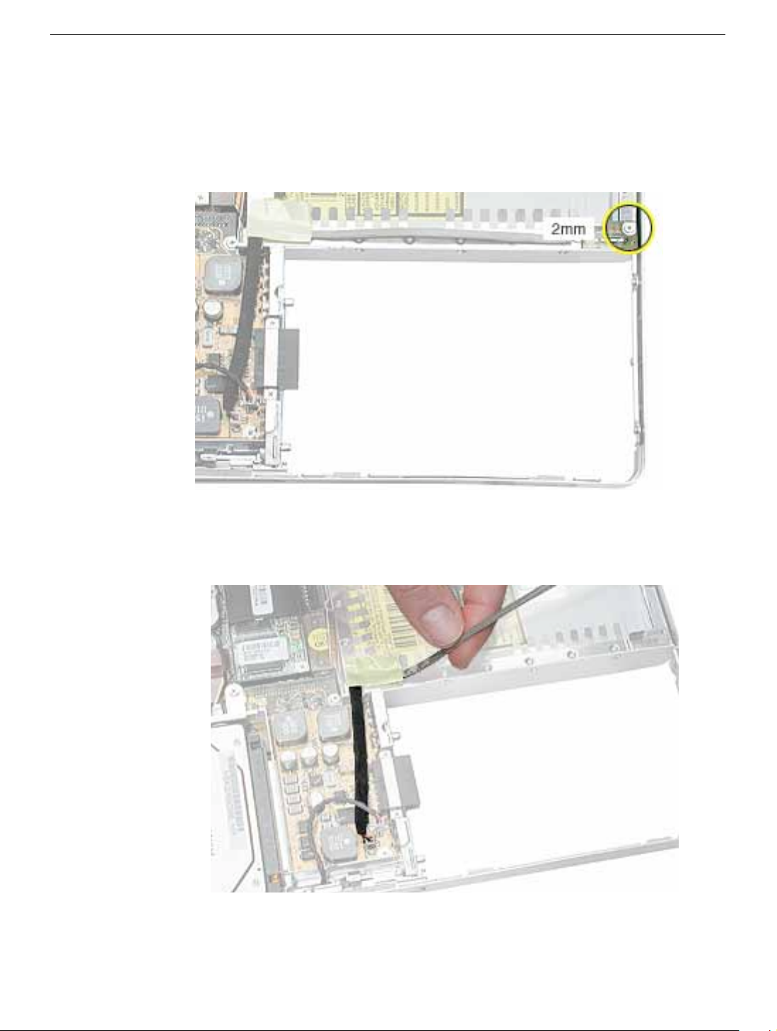
3. Disconnect the connector from the upper right corner of the logic board.
4. Remove the screw near the right corner of the frame.
5. Near the I/O ports, disconnect the
• long black cable from the 2-pin connector
• shorter black cable from the 4-pin connector
46 - PowerBook G4 (12-inch) Take Apart
Inner Frame
Page 49

6. Pull up the LVDS cable with the pull tab
Warning: Be careful not to strain the LVDS cable.
7. Remove the screw at the LVDS cable.
Replacement Note: When reinstalling the LVDS cable, tuck the pull tab under
the frame.
Inner Frame
PowerBook G4 (12-inch) Take Apart - 47
Page 50

8. Peel up the tape, and remove the screw at the RJ11 modem cable board.
9. Tilt up the RJ11 modem cable board and remove the 6-mm long screw (not shown)
that secures the frame to the logic board.
48 - PowerBook G4 (12-inch) Take Apart
Inner Frame
Page 51

10. Remove the two screws at the I/O ports.
11. Remove the EMI strip at the top of the I/O ports.
Inner Frame
PowerBook G4 (12-inch) Take Apart - 49
Page 52

12. Remove the three screws from the top of the heatsink.
13. Remove the two screws from the lower left corner of the computer assembly.
50 - PowerBook G4 (12-inch) Take Apart
Inner Frame
Page 53

14. Disconnect the optical drive flex cable.
15. Lift up the frame, being careful where it catches on the optical drive flex cable or other
cables.
Inner Frame
PowerBook G4 (12-inch) Take Apart - 51
Page 54

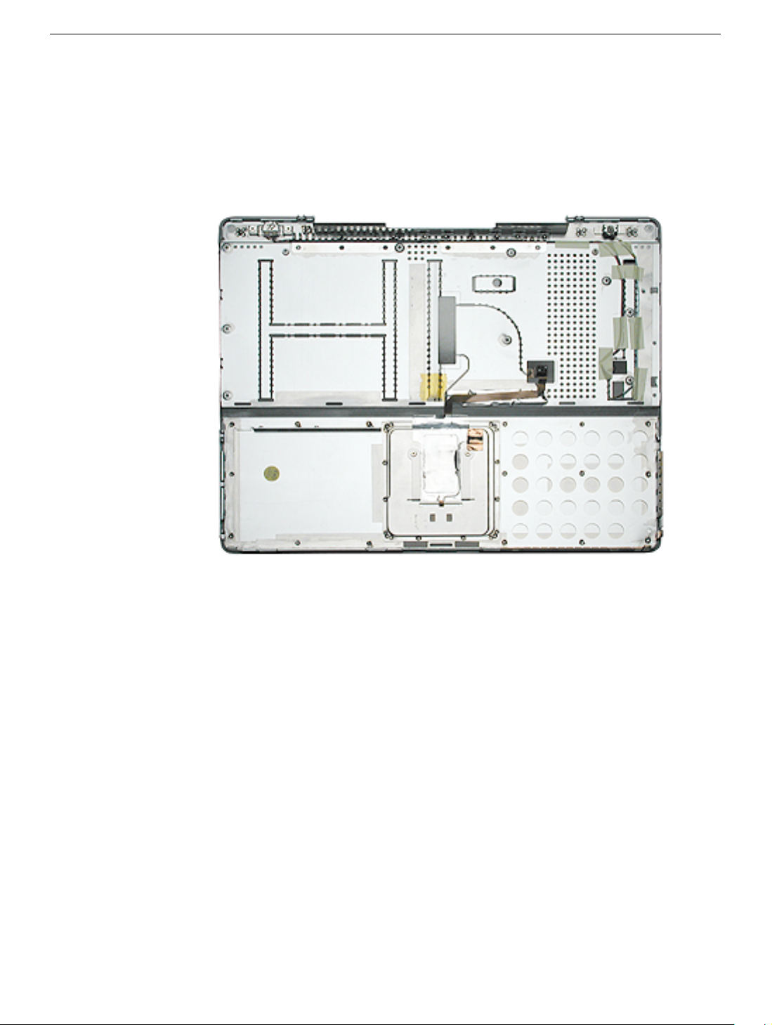
16. Lift the inner frame out of the computer assembly.
52 - PowerBook G4 (12-inch) Take Apart
Inner Frame
Page 55

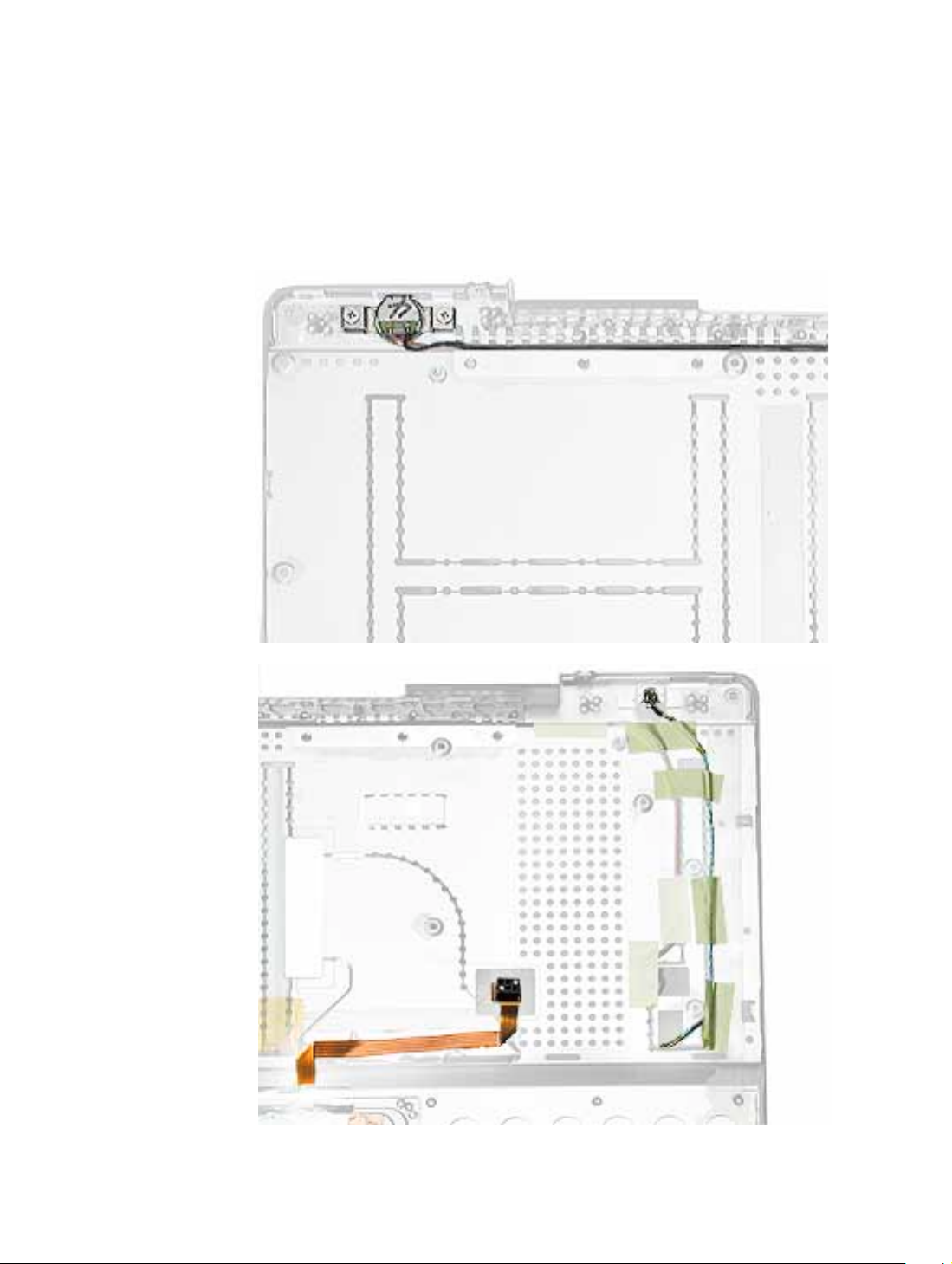
17. Install the replacement frame, and reassemble and test the computer.
Replacement Note: When installing the replacement frame, note the initial routing
of the cables, as shown in the following images:
Inner Frame
PowerBook G4 (12-inch) Take Apart - 53
Page 56

RJ11 Modem Board and Cable
Tools
This procedure requires the following tools:
• #0 Phillips screwdriver
• Black stick (or other nonconductive nylon or plastic flat-blade tool)
Note: To organize the screws you remove from the computer, use a tray with divided
compartments (such as a plastic ice cube tray).
Part Location
Preliminary Steps
Before you begin, remove the following:
• Battery
• Memory door and memory card
• Keyboard
• Top case
54 - PowerBook G4 (12-inch) Take Apart
RJ11 Modem Board and Cable
Page 57

Procedure
1. Disconnect the modem cable connector from the modem (Refer to the Modem
procedure in this chapter. You do not have to remove the modem board to disconnect
the cable.)
2. Remove the screw at the LVDS cable.
Replacement Note: When reinstalling the LVDS cable, tuck the pull tab under
the frame.
3. Peel up the tape that secures the LVDS cable.
RJ11 Modem Board and Cable
PowerBook G4 (12-inch) Take Apart - 55
Page 58

4. Remove the screw at the RJ11 board.
5. Use a black stick to tilt up the RJ11 board and lift it out of the inner frame.
56 - PowerBook G4 (12-inch) Take Apart
RJ11 Modem Board and Cable
Page 59

6. Remove the EMI shield from the RJ11 board. The board includes the attached cable
and connector.
7. Install the replacement RJ11 modem board and cable, and reassemble and test the
computer.
RJ11 Modem Board and Cable
PowerBook G4 (12-inch) Take Apart - 57
Page 60

Sleep Light
Tools
This procedure requires the following tools:
• #0 Phillips screwdriver
Part Location
Preliminary Steps
Before you begin, remove the following:
• Battery
• Memory door and memory card
• Keyboard
• Top case
• Reed switch
• Hard drive
• DC-to-DC board
• Modem
• Heatsink with fan
58 - PowerBook G4 (12-inch) Take Apart
Sleep Light
Page 61

• RJ11 board
• Inner frame
Procedure
1. Remove the screw from the sleep light board.
2. Remove the board from the bottom case.
Sleep Light
3. Replacement Note: Make sure the bottom case has the sleep light pipe installed
before installing the replacement sleep light board.
4. Install the replacement sleep light board, and reassemble and test the computer.
PowerBook G4 (12-inch) Take Apart - 59
Page 62

Logic Board
Tools
This procedure requires the following tools:
• #0 Phillips screwdriver
• Black stick (or other nonconductive nylon or plastic flat-blade tool)
Note: To organize the screws you remove from the computer, use a tray with divided
compartments (such as a plastic ice cube tray).
Part Location
Preliminary Steps
Before you begin, remove the following:
• Battery
• Memory door and memory card
• AirPort Extreme Card, if installed
• Keyboard
• Top case
60 - PowerBook G4 (12-inch) Take Apart
Logic Board
Page 63

• Reed switch
• Hard drive
• DC-to-DC board
• Modem
• Heatsink with fan
• RJ11 board
• Inner frame
Procedure
1. Remove the two screws near the right edge of the board.
Logic Board
PowerBook G4 (12-inch) Take Apart - 61
Page 64

2. Holding the edges of the board tilt up the logic board.
3. While holding the board vertically, disconnect the DC-in connector cable from the
underside of the logic board.
62 - PowerBook G4 (12-inch) Take Apart
Logic Board
Page 65

4. Remove the side EMI shield from the I/O ports.
Warning: When installing the EMI shield over the logic board ports, make
sure that the shield fits loosely and the ports are not obstructed.
5. Install the replacement logic board, and reassemble and test the computer.
Replacement Note: Before securing the replacement logic board in the bottom
case, make sure the white plastic wireless guide is fitted against the AirPort
Extreme Card carrier in the bottom case. (The wireless guide requires no
screws to hold it in place.)
Logic Board
PowerBook G4 (12-inch) Take Apart - 63
Page 66

DC-In Board
This procedure requires the following tools:
• #0 Phillips screwdriver
• Black stick (or other nonconductive nylon or plastic flat-blade tool)
Part Location
Preliminary Steps
Before you begin, remove the following:
• Battery
• Memory door and memory card
• AirPort Extreme Card, if installed
• Keyboard
• Top case
• Reed switch
• Hard drive
• DC-to-DC board
• Modem
64 - PowerBook G4 (12-inch) Take Apart
DC-In Board
Page 67

• Heatsink with fan
• RJ11 board
• Inner frame
• Logic board
Procedure
1. Hold the DC-in board in place as you remove the screw that attaches the board to the
bottom case.
DC-In Board
2. Pull the flat cable up from the adhesive on the bottom case.
3. Pull the board away from the side of the bottom housing. Use a black stick to lift up the
board, if necessary.
PowerBook G4 (12-inch) Take Apart - 65
Page 68

4. Remove the round port liner.
5. Install the replacement DC-in board, and reassemble and test the computer.
66 - PowerBook G4 (12-inch) Take Apart
DC-In Board
Page 69

Optical Drive
Tools
This procedure requires the following tools:
• #0 Phillips screwdriver
• Black stick (or other nonconductive nylon or plastic flat-blade tool)
Note: To organize the screws you remove from the computer, use a tray with divided
compartments (such as a plastic ice cube tray).
Part Location
Optical Drive
Preliminary Steps
Before you begin, remove the following:
• Battery
• Memory door and memory card
• AirPort Extreme Card, if installed
• Keyboard
PowerBook G4 (12-inch) Take Apart - 67
Page 70

• Top case
• Reed switch
• Hard drive
• DC-to-DC board
• Modem
• Heatsink with fan
• RJ11 board
• Inner frame
• Logic board
Procedure
1. Remove the two screws from the shoulder bracket at the upper right corner of the
optical drive.
68 - PowerBook G4 (12-inch) Take Apart
Optical Drive
Page 71

2. Use a black stick to remove the shoulder bracket.
3. Remove the two screws from the slot load bezel.
Replacement Note: When installing the replacement optical drive in the bottom
case, make sure the slot load bezel is flush against the slot in the side of the bottom
case before installing the screws.
Optical Drive
PowerBook G4 (12-inch) Take Apart - 69
Page 72

4. Tilt up the optical drive and remove it from the computer.
5. Remove the screws from the L-shaped EMI bracket on the top of the drive. Lift off the
bracket.
70 - PowerBook G4 (12-inch) Take Apart
Optical Drive
Page 73

6. Turn over the drive and remove the three screws from the L-shaped EMI bracket on
the bottom of the drive.
7. Remove the bottom L-shaped EMI bracket.
Optical Drive
PowerBook G4 (12-inch) Take Apart - 71
Page 74

8. Use a black stick to press the tabs and remove the slot load bezel. Pull the bezel
straight off the drive.
9. Disconnect the flex cable.
10. Install the replacement optical drive, and reassemble and test the computer.
72 - PowerBook G4 (12-inch) Take Apart
Optical Drive
Page 75

Bluetooth
Tools
This procedure requires the following tools:
• #0 Phillips screwdriver
• Black stick (or other nonconductive nylon or plastic flat-blade tool)
Part Location
Bluetooth
Preliminary Steps
Before you begin, remove the following:
• Battery
• Memory door and memory card
• AirPort Extreme Card, if installed
• Keyboard
• Top case
• Reed switch
• Hard drive
PowerBook G4 (12-inch) Take Apart - 73
Page 76

• DC-to-DC board
• Modem
• Heatsink with fan
• RJ11 board
• Inner frame
• Logic Board
• Optical drive
Procedure
Warning: The subwoofer, located to the left of the Bluetooth board, is a sensitive device.
Avoid touching the subwoofer as you perform this procedure.
Warning: To avoid excessive pressure on the Bluetooth board, hold the edge of the board
in place as you perform this procedure.
1. If tape covers part of the board, hold the board in place as you remove the tape.
2. Use a black stick to disconnect the 4-pin connector from the board.
3. Holding the Bluetooth cable connector, pull it straight up to disconnect it.
4. Remove the screw from the Bluetooth board.
5. Remove the Bluetooth board from the bottom case.
6. Install the replacement Bluetooth, and reassemble and test the computer.
74 - PowerBook G4 (12-inch) Take Apart
Bluetooth
Page 77

Subwoofer
Tools
This procedure requires the following tools:
• #0 Phillips screwdriver
• Black stick (or other nonconductive nylon or plastic flat-blade tool)
Part Location
Subwoofer
Note: In the image above, the Bluetooth cable appearance differs from the production
models of this computer.
Procedure
Note: Refer to the "Display Module" procedure. You can remove the subwoofer while it is
still in the bottom case (and before removing the display) by removing the tape and the
single screw from the subwoofer.
PowerBook G4 (12-inch) Take Apart - 75
Page 78

Display Module
Tools
This procedure requires the following tools:
• #0 Phillips screwdriver
• #1 Phillips screwdriver
• Black stick (or other nonconductive nylon or plastic flat-blade tool)
Note: To organize the screws you remove from the computer, use a tray with divided
compartments (such as a plastic ice cube tray).
Part Location
Preliminary Steps
Before you begin, remove the following:
• Battery
• Memory door and memory card
• AirPort Extreme Card, if installed
• Keyboard
76 - PowerBook G4 (12-inch) Take Apart
Display Module
Page 79

• Top case
• Reed switch
• Hard drive
• DC-to-DC board
• Modem
• Heatsink with fan
• RJ11 board
• Inner frame
• Logic Board
• Optical drive
• Bluetooth
• DC-in board
Procedure
Important: This procedure show s the subwoofer and inner rear panel attached to the
display module when it is removed from the bottom case. However, you can remove the
subwoofer from the bottom case you do not need to remove the subwoofer and display
module together.
1. With the computer upside down, remove the two screws from the bottom case.
Display Module
PowerBook G4 (12-inch) Take Apart - 77
Page 80

2. Remove the screws near the display hinge.
3. From the inside of the bottom case, remove the tape from the antenna cable.
78 - PowerBook G4 (12-inch) Take Apart
Display Module
Page 81

4. Route the AirPort antenna cable through the AirPort Extreme Card bay.
5. Remove the screw from the subwoofer.
Display Module
Note: In the image above, the Bluetooth cable appearance differs from the
production models of this computer.
PowerBook G4 (12-inch) Take Apart - 79
Page 82

6. Peel the tape off of the subwoofer.
Warning: The cone of the subwoofer is a sensitive device. Avoid touching the
subwoofer cone as you perform this procedure.
Note: In the image above, the Bluetooth cable appearance differs from the
production models of this computer.
7. Note: The back edge of the subwoofer adheres to the rear panel.
Use a black stick to pry open the adhesive seal at the rear panel. Pivot the
subwoofer away from the rear panel, and remove the subwoofer from the
bottom case.
80 - PowerBook G4 (12-inch) Take Apart
Display Module
Page 83

8. With the display open to a 90-degree angle, lift off the displa y with attached subwoof er
and inner rear frame.
Important: The display might get caught on the hooks (shown below) on the
bottom case. If so, carefully reposition the display so it is laying face up with
the attached bottom case standing vertically. Gently twist the bottom case to
release it from the display.
Display Module
PowerBook G4 (12-inch) Take Apart - 81
Page 84

9. Remove the four screws from the display’s inner rear panel. Make sure the
screwdriver does not touch the speakers.
10. Remove the inner rear panel with attached speakers b y routing the cab les through the
slots in the rear panel.
Replacement Note: When installing the rear panel, hold the routed cables
away from the path of the screws.
82 - PowerBook G4 (12-inch) Take Apart
Display Module
Page 85

Replacement Note: When installing the rear panel, check that the twisted
pair of speaker cables is completely recessed in the panel and that the tape
holds the cables in place.
Replacement Note: Check that the orientation of the cables directed through
the rear panel openings are as shown below:
Display Module
PowerBook G4 (12-inch) Take Apart - 83
Page 86

11. Install the replacement display module, and reassemble and test the computer.
84 - PowerBook G4 (12-inch) Take Apart
Display Module
Page 87

Bottom Case
Part Location
Bottom Case
Preliminary Steps
Before you begin, remove the following:
• Battery
• Memory door and memory card
• AirPort Extreme Card, if installed
• Keyboard
• Top case
• Reed switch
• Hard drive
• DC-to-DC board
• Modem
• Heatsink with fan
• RJ11 board
• Inner frame
• Sleep light board
• Logic board
PowerBook G4 (12-inch) Take Apart - 85
Page 88

• DC-in board
• Optical drive
• Bluetooth
• Subwoofer
• Display module
Procedure
When all preliminary steps are performed, the bottom case is the part that remains.
86 - PowerBook G4 (12-inch) Take Apart
Bottom Case
Page 89

Display Housing
Tools
This procedure requires the following tools:
• 1.5 mm hex driver
• Black stick (or other nonconductive nylon or plastic flat-blade tool)
• Optional: Credit card (or other thin plastic card)
Part Location
Display Housing
Preliminary Steps
Before you begin, remove the following:
• Battery
• Memory door and memory card
• AirPort Extreme Card, if installed
• Keyboard
• Top case
• Reed switch
PowerBook G4 (12-inch) Take Apart - 87
Page 90

• Hard drive
• DC-to-DC board
• Modem
• Heatsink with fan
• RJ11 board
• Inner frame
• Logic board
• DC-in board
• Optical drive
• Display module
Procedure
1. Remove the two 5-mm long hex screws from the front bezel.
88 - PowerBook G4 (12-inch) Take Apart
Display Housing
Page 91

2. Use a black stick or thin plastic credit card around the outer edge of the bezel to
separate the display housing tabs from the display assembly.
Warning: To avoid damage to the antenna receptors or inner cables, do not
poke the black stick or credit card inside the display. Keep the tool at a nearly
horizontal plane with the display bezel as you loosen the display assembly
from the display housing.
Note: In the image above, the Bluetooth cable appearance differs from the
production models of this computer.
Display Housing
PowerBook G4 (12-inch) Take Apart - 89
Page 92

3. Lift the display assembly off of the display housing.
4. Note the routing of the antenna cables. Peel up the tape that holds the cables in place .
Warning: Handle the antenna receptors and cables with care. Do not strain or
pinch the cables. Do not apply pressure to or bend the antenna receptors.
5. Disconnect the antenna cables and receptors on each side of the display housing.
Warning: The hooks that hold the antenna cables in place are delicate. Use care
when disconnecting the cables.
90 - PowerBook G4 (12-inch) Take Apart
Display Housing
Page 93

6. Remove the display housing.
7. Install the replacement display housing, and reassemble and test the computer.
Display Housing
PowerBook G4 (12-inch) Take Apart - 91
Page 94

LCD Panel
Tools
This procedure requires the following tools:
• Phillips #0 screwdriver
• Black stick or other nonconductive plastic or nylon tool
Part Location
Preliminary Steps
Before you begin, remove the following:
• Battery
• Memory door and memory card
• AirPort Extreme Card, if installed
• Keyboard
• Top case
• Reed switch
• Hard drive
92 - PowerBook G4 (12-inch) Take Apart
LCD Panel
Page 95

• DC-to-DC board
• Modem
• Heatsink with fan
• RJ11 board
• Inner frame
• Logic board
• DC-in board
• Optical drive
• Display module
• Display housing
Procedure
Note: Reuse the tape you remove from the LCD panel.
1. Hold the backing for the LCD panel in place as you peel off the tape and disconnect
the LCD cable.
LCD Panel
PowerBook G4 (12-inch) Take Apart - 93
Page 96

2. Remove the two screws from each side of the LCD panel.
94 - PowerBook G4 (12-inch) Take Apart
LCD Panel
Page 97

3. Lift off the long EMI clip at the base of the bezel.
4. Raise up the LCD panel and disconnect the connector to the inverter board.
5. Install the replacement LCD panel, and reassemble and test the computer.
Replacement Note: When installing the replacement LCD panel in the display
bezel assembly, make sure the cable is connected to the inverter board and
routed as shown.
LCD Panel
PowerBook G4 (12-inch) Take Apart - 95
Page 98

Inverter Board (and Antenna Cable Assembly)
Tools
This procedure requires the following tools:
• Phillips #0 screwdriver
• Black stick or other nonconductive plastic or nylon tool
Note: To organize the screws you remove from the computer, use a tray with divided
compartments (such as a plastic ice cube tray).
Part Location
Preliminary Steps
Before you begin, remove the following:
• Battery
• Memory door and memory card
• AirPort Extreme Card, if installed
• Keyboard
• Top case
• Reed switch
96 - PowerBook G4 (12-inch) Take Apart
Inverter Board (and Antenna Cable Assembly)
Page 99

• Hard drive
• DC-to-DC board
• Modem
• Heatsink with fan
• RJ11 board
• Inner frame
• Logic board
• DC-in board
• Optical drive
• Display module
• Display housing
• LCD panel
Procedure
1. Remove the single screw near the center of the inverter board.
Inverter Board (and Antenna Cable Assembly)
PowerBook G4 (12-inch) Take Apart - 97
Page 100

2. Lift up the board.
3. Peel away the tape and mylar cover that holds the inverter board and the antenna
cable assembly together.
98 - PowerBook G4 (12-inch) Take Apart
Inverter Board (and Antenna Cable Assembly)
 Loading...