

Page 1

K
Service Source
PowerBook Duo MiniDock
Page 2

K
Service Source
Basics
PowerBook Duo MiniDock
Page 3
Basics System Overview - 1
System Overview
PowerBook Duo
System
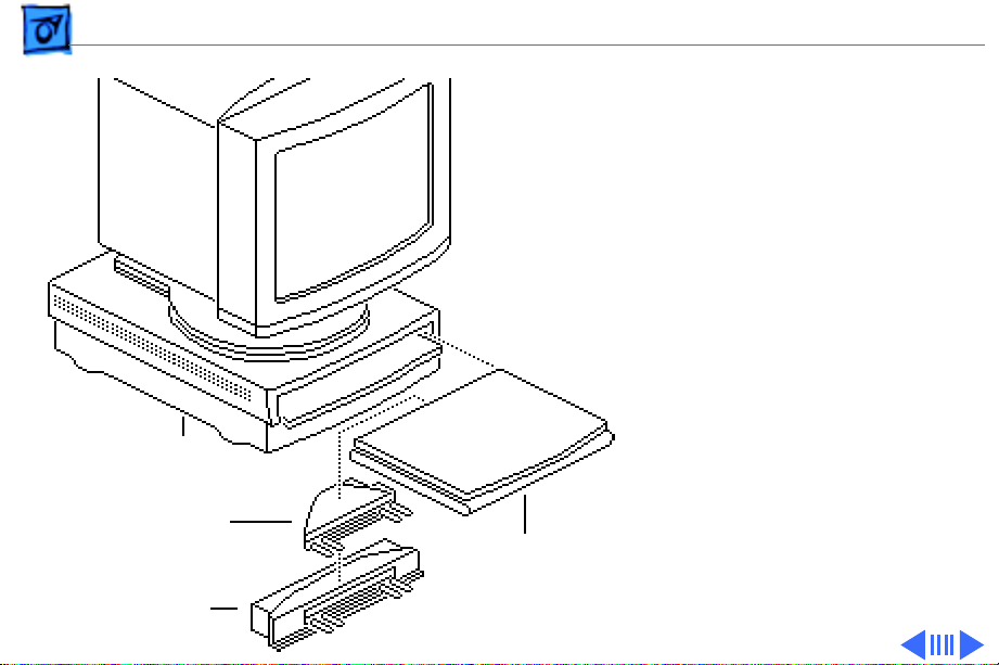
The PowerBook Duo system
includes the following
products:
• PowerBook 200 Series
computer (PowerBook
Duo 210/230/250/
Duo Dock/
Duo Dock II/
Duo Dock Plus
Duo Floppy
Adapter
Duo MiniDock
Duo
210/230
250/270c
280/280c
270c/280/280c)
• PowerBook Duo Dock/Duo
Dock II/Duo Dock Plus
Page 4
Basics System Overview - 2
• PowerBook Duo Floppy
Adapter
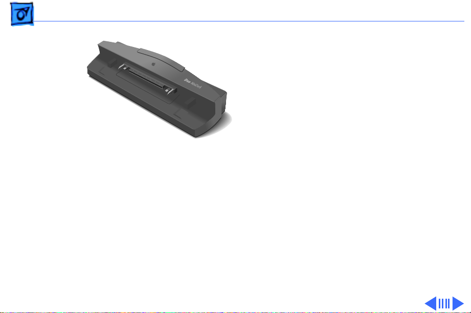
• PowerBook Duo MiniDock
This manual includes
information about the
PowerBook Duo MiniDock.
Figure: PowerBook Duo MiniDock
Page 5

Basics System Overview - 3
For information about the floppy adapter and the PowerBook
200 Series computers, refer to the PowerBook 200 Series
manual. For information about the Duo Docks, refer to the
PowerBook Duo Dock manual.
Page 6

Basics Repair Strategy - 4
Repair Strategy
Service the PowerBook Duo MiniDock through module
exchange and parts replacement. Customers can request onsite service from an Apple Authorized Service Provider Plus
(AASP+) Apple Assurance (US only), or request a courier
through the Apple Canada Technical Answerline (Canada
only). They can also choose carry-in service from an AASP.
Page 7

Basics Repair Strategy - 5
Ordering
Apple Service Providers planning to support the product
covered in this manual may purchase Service modules and
parts to develop servicing capability. To order parts, use the
AppleOrder (US only) or ARIS (Canada only) system and
refer to “Service Price Pages.”
Large businesses, universities, and K-12 accounts must
provide a purchase order on all transactions, including
orders placed through the AppleOrder (US only) or ARIS
(Canada only) system.
USA Ordering
US Service Providers not enrolled in AppleOrder may fax
their orders to Service Provider Support (512-908-
8125) or mail them to
Page 8

Basics Repair Strategy - 6
Apple Computer, Inc.
Service Provider Support
MS 212-SPS
Austin, TX 78714-9125
For US inquiries, please call Service Provider Support at
800-919-2775 and select option #1.
Canadian Ordering
Canadian Service Providers not enrolled in ARIS may fax
their orders to Service Provider Support in Canada
(1-800-903-5284). For Canadian inquiries, please call
Service Provider Support at 905-513-5782 and select
option #3.
Page 9

Basics Warranty/AppleCare/ARIS - 7
Warranty/AppleCare/ARIS
US Only
The PowerBook Duo MiniDock is covered under the Apple
One-Year Limited Warranty. The AppleCare Service Plan is
also available for this product. Service Providers are
reimbursed for warranty and AppleCare repairs made to
this product. For pricing information, refer to “Service
Price Pages.”
Canada Only
The PowerBook Duo MiniDock is covered under first-year
AppleCare. The Extended AppleCare Service Plan is also
available for this product. Service Providers are
reimbursed for first-year warranty and Extended
AppleCare repairs made to this product. For pricing
information, refer to “Service Price Pages.”
Page 10
Basics Self-Threading Screws - 8
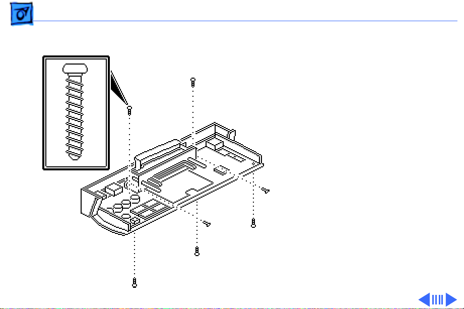
Self-Threading Screws
Self-Threading
Screws
Caution:
installed self-threading
screws could damage the Duo
MiniDock.
The PowerBook Duo
MiniDock uses selfthreading screws. When you
are replacing a selfthreading screw, follow
these guidelines:
• Never overtighten selfthreading screws.
Improperly
Page 11

Basics Self-Threading Screws - 9
• Before tightening a selfthreading screw, back the
screw off slightly to be
sure it is threaded
properly.
Page 12

K
Service Source
Specifications
PowerBook Duo MiniDock
Page 13

Specifications Introduction - 1
Introduction
You can also find specifications information for this product in the
Spec Database, which you can access in one of three ways:
— Launch it directly by double-clicking the Apple Spec Database
runtime alias at the top level of the Main Service Source CD.
— Select "Apple Spec Database" from the Service Source drop-
down main menu.
— Click the Acrobat toolbar icon for the database, which is near
the right end of the toolbar with the letters "SP."
Page 14

Specifications Processor - 2
Processor
Addressing
32-bit internal registers
32-bit address bus
32-bit data bus
Page 15

Specifications Memory - 3
Memory
VRAM
512K VRAM
Supports all Macintosh monitors up to 16-in. color
Supports some VGA monitors with adapter and NuBus card
Supports 256 colors or shades of gray
Page 16

Specifications I/O Interfaces - 4
I/O Interfaces
Docking Connector
Floppy Drive
SCSI
Internal 152-pin processor-direct slot (PDS) connector to
PowerBook Duo
32-bit expansion bus
HDI-20 port for external 1.4 MB floppy drive (MS-DOS
compatible)
HDI-30 SCSI port with 1.5 MB/sec. transfer rate
Supports up to five external SCSI devices
Includes built-in terminator
Connection to another computer requires HDI-30 SCSI system
cable
Page 17

Specifications I/O Interfaces - 5
Apple Desktop Bus
Serial
Sound
Video
Modem
Apple Desktop Bus (ADB) port (recommend maximum of three
low-speed, synchronous ADB devices); mini DIN-4 connector
200 mA maximum current draw for all ADB devices
Two RS-422 serial ports; mini DIN-8 connectors
Monaural sound-in port (requires 20 dB attenuation cables and
adapters to accommodate audio equipment with line level
outputs)
Monaural sound output jack for external audio amplifier
DB-15 connector supports Macintosh and VGA monitors (requires
15-pin-to-VGA adapter)
Pass-through telephone jack for optional internal PowerBook
Express Modem RJ-11 domestic; mini DIN-8 international
Page 18

Specifications Electrical - 6
Electrical
Power Supply
Universal AC power supply, 85–270 VAC
47–63 Hz, single phase input line frequency
Page 19

Specifications Physical - 7
Physical
Dimensions
Weight
Height: 2.1 in. (53 mm)
Width: 10.6 in. (269 mm)
Depth: 3.2 in. (81 mm)
1.24 lb. (0.56 kg)
Page 20

Specifications Environmental - 8
Environmental
Operating
Temperature
Storage
Temperature
Relative Humidity
Altitude
50–104° F (10–40° C)
–40 to 116° F (–40 to 47° C)
20–95% noncondensing
0–15,000 ft. (0–4722 m)
Page 21

Specifications Other - 9
Other
Options
Slot for security cable
Modem expander (domestic or international telephone jack)
Page 22

K
Service Source
Troubleshooting
PowerBook Duo MiniDock
Page 23

Troubleshooting General/ - 1
General
The Symptom Charts included in this chapter will help you
diagnose specific symptoms related to your product. Because cures
are listed on the charts in the order of most likely solution, try
the first cure first. Verify whether or not the product continues to
exhibit the symptom. If the symptom persists, try the next cure.
(Note: If you have replaced a module, reinstall the original module
before you proceed to the next cure.)
If you are not sure what the problem is, or if the Symptom Charts
do not resolve the problem, refer to the Flowchart for the product
family.
For additional assistance, contact Apple Technical Support.
Page 24

Troubleshooting Symptom Charts/Startup - 2
Symptom Charts
Startup
RAM failure occurs
(eight-tone error
chord sequence
sounds after startup
chord)
Hardware failure
occurs (four-tone
error chord sequence
sounds after startup
chord)
1 Disconnect Duo MiniDock from PowerBook. Reboot and
troubleshoot computer only.
2 Replace Duo MiniDock logic board.
1 Disconnect Duo MiniDock from PowerBook Duo. Reboot and
troubleshoot computer only.
2 Replace Duo MiniDock logic board.
Page 25

Troubleshooting Symptom Charts/Power - 3
Power
System doesn’t
respond
System
intermittently
crashes or locks up
1 Disconnect Duo MiniDock from PowerBook Duo. Reboot and
troubleshoot computer only.
2 Check all Duo MiniDock logic board cable connections.
3 Replace Duo MiniDock logic board.
1 Make sure system software is 7.1 or higher.
2 Make sure software is known-good.
3 Disconnect Duo MiniDock from PowerBook Duo. Reboot and
troubleshoot computer only.
4 Replace Duo MiniDock logic board.
Page 26

Troubleshooting Symptom Charts/Video - 4
Video
No external display,
but computer
appears to operate
correctly
Raster or video
display problems at
external monitor
1 Adjust screen contrast.
2 Reseat video cable.
3 Replace video cable.
4 Try known-good external display. If now OK, replace and
troubleshoot original display.
5 Replace Duo MiniDock logic board.
1 Reseat video cable.
2 Replace video cable.
3 Try known-good external display. If now OK, replace and
troubleshoot original display.
4 Replace Duo MiniDock logic board.
Page 27

Troubleshooting Symptom Charts/Floppy Drive - 5
Floppy Drive
Audio and video
present, but external
floppy drive does not
operate
Disk ejects while
booting; display
shows Mac icon with
blinking X
1 Try known-good floppy disk.
2 Check floppy drive cable connection.
3 Replace floppy drive cable.
4 Replace floppy drive.
5 Replace Duo MiniDock logic board.
1 Try known-good system disk.
2 Verify that mouse or trackball button is not stuck.
3 Check floppy drive cable connection.
4 Replace floppy drive cable.
5 Replace floppy drive.
6 Replace Duo MiniDock logic board.
Page 28

Troubleshooting Symptom Charts/Floppy Drive
(Continued)
- 6
Floppy Drive
Disk does not eject 1 Switch off system. To eject disk, hold mouse or trackball
button down while you switch system on.
2 Insert straightened paper clip into hole next to drive opening
and eject disk.
3 Check floppy drive cable connection.
4 Replace floppy drive cable.
5 Replace floppy drive.
6 Replace Duo MiniDock logic board.
Disk initialization
fails
1 Verify that you are using correct media.
2 Try known-good floppy disk.
3 Check floppy drive cable connection.
4 Replace floppy drive cable.
5 Replace floppy drive.
(Continued)
Page 29

Troubleshooting Symptom Charts/Floppy Drive
(Continued)
- 7
Read/write/copy
error
Floppy Drive
1 Verify that you are using correct media.
2 Try known-good floppy disk.
3 Check floppy drive cable connection.
4 Replace floppy drive cable.
5 Replace floppy drive.
(Continued)
Page 30

Troubleshooting Symptom Charts/Hard Drive - 8
Hard Drive
Internal PowerBook
hard drive does not
operate
External hard drive
does not operate
Drive does not appear
on desktop
Disconnect Duo MiniDock from PowerBook Duo. Reboot and
troubleshoot computer only.
1 Check hard drive cable connection.
2 Replace hard drive cable.
3 Run Macintosh Hard Disk Test.
4 Use HD SC Setup to reinitialize drive.
5 Replace hard drive.
6 Replace Duo MiniDock logic board.
1 Restart system.
2 Verify that SCSI devices have unique addresses.
3 Use HD SC Setup to initialize drive.
Page 31

Troubleshooting Symptom Charts/Peripherals - 9
Peripherals
Cursor does not
move, or moves
erratically
Cursor moves, but
clicking mouse
button has no effect
1 Simultaneously press <Command> <Control> <Power On> keys
to reset computer.
2 Check ADB connections.
3 Inspect and clean mouse, if necessary.
4 If mouse was connected to keyboard, try in ADB port. If OK,
replace keyboard.
5 Replace mouse.
6 Replace Duo MiniDock logic board.
1 Replace mouse.
2 Replace Duo MiniDock logic board.
Page 32

Troubleshooting Symptom Charts/Peripherals
(Continued)
- 10
No response to any
key on keyboard
Cannot double-click
to open application,
disk, or server
Peripherals
1 Press <Power On> key or power button.
2 Check keyboard cable connection.
3 Replace keyboard cable.
4 Replace keyboard.
5 Replace Duo MiniDock logic board.
1 Remove any multiple system files.
2 Inspect and clean mouse, if necessary.
3 Clear parameter RAM and reset mouse controls. To clear
PRAM, start system, listen for boot tone, and immediately
depress <Option> <Command> <P> and <R> keys.
4 If mouse was connected to keyboard, try in ADB port. If OK,
replace keyboard.
5 Replace mouse.
6 Replace Duo MiniDock logic board.
(Continued)
Page 33

Troubleshooting Symptom Charts/Peripherals
(Continued)
- 11
After you connect
external SCSI device,
computer doesn’t boot
Known-good
ImageWriter,
ImageWriter II, or
LQ does not print
Peripherals
1 Switch on external SCSI device before starting computer.
2 Check cable connections.
3 Verify that standard Apple terminator terminates SCSI chain.
4 Verify that SCSI select switch setting on external device is
unique.
5 Try known-good external SCSI device.
6 Replace Duo MiniDock logic board.
1 Verify that System is 7.1 or later.
2 Verify that Chooser and Control Panel settings are correct.
3 Check cables.
4 Replace printer interface cable.
5 Try known-good printer.
6 Replace Duo MiniDock logic board.
(Continued)
Page 34

Troubleshooting Symptom Charts/Peripherals
(Continued)
- 12
Known-good
LaserWriter does not
print
Peripherals
1 Verify that System is 7.1 or later.
2 Verify that Chooser and Control Panel settings are correct.
3 Check cables.
4 Replace printer interface cable.
5 Try known-good printer. If printer works, troubleshoot
network.
6 Replace Duo MiniDock logic board.
(Continued)
Page 35

Troubleshooting Symptom Charts/Peripherals
(Continued)
- 13
Device connected to
external modem port
doesn’t work
Peripherals
1 Verify that External Modem is selected in PowerBook Control
Panel.
2 Verify that System is 7.1 or later.
3 Check cables.
4 Test device with known-good computer.
5 Disconnect Duo MiniDock from PowerBook and test device at
PowerBook external modem/printer port.
6 Replace Duo MiniDock modem interface card.
7 Replace Duo MiniDock logic board.
(Continued)
Page 36

Troubleshooting Symptom Charts/Peripherals
(Continued)
- 14
I/O devices are
unrecognized or
garbage is
transmitted or
received
Peripherals
1 Verify that System is 7.1 or later.
2 Check cables.
3 Verify that SCSI devices are terminated properly.
4 Verify that SCSI select switch setting on external device is
unique and between 2 and 6.
5 Test device with known-good computer.
6 Replace Duo MiniDock logic board.
(Continued)
Page 37

Troubleshooting Symptom Charts/Internal Modem - 15
Internal Modem
Internal modem
options do not appear
in CDEV
1 Verify that System is 7.1 or later.
2 Remove and reseat modem interface board.
3 Disconnect Duo MiniDock from PowerBook and test
PowerBook internal modem.
4 Replace modem interface board.
5 Replace Duo MiniDock logic board.
Page 38

Troubleshooting Symptom Charts/Internal Modem
(Continued)
- 16
Modem does not
respond properly to
AT command set
instructions
Internal Modem
1 Verify that baud rate and data format settings of
communications application are compatible with internal
modem and remote modem.
2 Check phone cord connection and operation.
3 Verify that System is 7.1 or later.
4 Remove and reseat modem interface board.
5 Disconnect Duo MiniDock from PowerBook and test
PowerBook internal modem.
6 Replace modem interface board.
7 Replace Duo MiniDock logic board.
(Continued)
Page 39

Troubleshooting Symptom Charts/Internal Modem
(Continued)
- 17
Strange mix of
characters appears
on screen
Modem interferes
with system sound
Internal Modem
1 Verify that baud rate and data format settings of
communications application are compatible with internal
modem and remote modem.
2 Check phone cord connection and operation.
3 Verify that System is 7.1 or later.
4 Remove and reseat modem interface board.
5 Disconnect Duo MiniDock from PowerBook and test
PowerBook internal modem.
6 Replace modem interface board.
7 Replace Duo MiniDock logic board.
1 Remove and reseat modem interface board.
2 Disconnect Duo MiniDock from PowerBook and test
PowerBook internal modem.
3 Replace modem interface board.
4 Replace Duo MiniDock logic board.
(Continued)
Page 40

Troubleshooting Symptom Charts/Internal Modem
(Continued)
- 18
Modem does not
respond to incoming
call
Modem has no sound
output
Internal Modem
1 If computer is in sleep mode, verify that “Answer calls” is
selected in Remote Access Setup control panel.
2 Check phone cord connection and operation.
3 Disconnect Duo MiniDock from PowerBook and test
PowerBook internal modem.
4 Replace modem interface board.
5 Replace Duo MiniDock logic board.
1 Verify that Control Panel volume setting is 1 or higher.
2 Disconnect Duo MiniDock from PowerBook and test
PowerBook internal modem.
3 Replace modem interface board.
4 Replace Duo MiniDock logic board.
(Continued)
Page 41

Troubleshooting Symptom Charts/Internal Modem
(Continued)
- 19
Modem connects but
does not communicate
with remote modem
Internal Modem
1 Verify that remote modem needs error correction (error
correction is internal modem default).
2 Type AT &Q0 to disable error correction.
(Continued)
Page 42

Troubleshooting Symptom Charts/Miscellaneous - 20
Miscellaneous
Can’t connect/
disconnect MiniDock
Replace mechanical latch.
Page 43

K
Service Source
T ak e Apart
PowerBook Duo MiniDock
Page 44

Take Apart Top Cover - 2
Top Cover
Before you begin,
Top Cover
• Shut down unit
• Disconnect PowerBook
Duo
• Disconnect cables
1 Using a T-6 torx driver,
remove the three selfthreading torx screws
that secure the top
cover to the bottom
cover.
Page 45

Take Apart Top Cover - 3
2
Note:
To separate the
top cover from the base,
Top Cover
Mechanical
Release Lever
you must first close the
mechanical release
lever. Push it in flush
with the top cover.
Carefully separate the
top and bottom covers
until the covers
disengage at the rear
mounting tabs.
Bottom Cover
Page 46

Take Apart Mechanical Latch - 4
Mechanical Latch
Before you begin, remove
the top cover.
Mechanical Latch
Caution:
Duo MiniDock contains CMOS
devices that are very
susceptible to ESD damage.
Review the ESD precautions
in Bulletins/Safety.
The PowerBook
Page 47

Take Apart Mechanical Latch - 5
1 Using a T-6 torx driver,
remove the two selfthreading screws that
Mechanical Latch
secure the plastic
faceplate to the
mechanical latch.
2 Pull the faceplate
straight off the
mechanical latch.
Note:
Before returning a
defective mechanical latch,
Faceplate
replace the faceplate on the
mechanical latch alignment
posts.
Page 48

Take Apart Mechanical Latch - 6
3 Using a T-6 torx driver,
remove the two selfthreading torx screws
that secure the
Mounting Tab
mechanical latch and
logic board to the bottom
cover.
Mechanical
Latch
4 Pull away the flex cable
and lift off the
mechanical latch.
Replacement Note:
When
replacing the mechanical
latch on the logic board,
insert the two mounting tabs
on the latch through holes in
the flex cable.
Page 49

Take Apart Logic Board - 7
Logic Board
Before you begin, remove
the following:
• Top cover
• Mechanical latch
Logic Board
Caution:
Duo MiniDock contains CMOS
devices that are very
susceptible to ESD damage.
Review the ESD precautions
in Bulletins/Safety.
The PowerBook
Page 50

Take Apart Logic Board - 8
1 Slightly raise the front
Modem Interface Card
of the logic board and
pull the board out of the
bottom cover.
Logic Board
Screw Mounts
2 Disconnect the modem
interface card (if
installed) from
connector J6.
Replacement Note:
When
replacing the logic board,
be careful not to bend the
metal grounding tabs on the
bottom cover, and make sure
the logic board snaps onto
the two bottom-cover screw
mounts.
Page 51

Take Apart Logic Board - 9
Flex Circuit
Stabilizer
Tie Wrap
PDS Interface Cable
Replacement Caution:
Before returning a defective
logic board, always install
the flex circuit stabilizer on
the PDS interface cable.
Remove the flex cable
stabilizer from the
replacement module and
position it behind the flex
cable as shown. Secure the
stabilizer to the logic board
with a tie wrap.
Page 52

Take Apart Bottom Cover - 10
Bottom Cover
To access the bottom cover,
remove the following:
• Top cover
• Mechanical latch
Bottom Cover
• Logic board
Caution:
Duo MiniDock contains CMOS
devices that are very
susceptible to ESD damage.
Review the ESD precautions
in Bulletins/Safety.
Note:
includes a white insulator.
The PowerBook
The bottom cover
Page 53

Take Apart Link - 11
Link
Before you begin, remove
the top cover.
Link
Caution:
Duo MiniDock contains CMOS
devices that are very
susceptible to ESD damage.
Review the ESD precautions
in Bulletins/Safety.
The PowerBook
Page 54

Take Apart Link - 12
±
Release Lever
Link
Mounting Clip
Warning:
the mounting clips from the
posts at the ends of the latch.
These clips secure the link,
which is under pressure,
and prevent the link from
springing up and striking
you.
1 Open (pull up) the
mechanical release
lever.
2 Remove the center of the
link from the metal
mounting brace.
3 Slide the ends of the link
from the mounting clips.
Never remove
Page 55

K
Service Source
Upgrades
PowerBook Duo MiniDock
Page 56

Upgrades Modem Interface Card - 1
Modem Interface Card
Before you begin, remove
the following:
• Top cover
• Mechanical latch
• Logic board
Modem Interface
Card
Page 57

Upgrades Modem Interface Card - 2
Note:
The modem interface
card provides telephone line
interface (DAA) circuitry
for a PowerBook Duo with an
internal modem. To address
the differences in telephone
interfaces and
specifications, Apple
provides both domestic and
international versions of the
modem interface card.
Page 58

Upgrades Modem Interface Card - 3
Caution:
Duo MiniDock contains CMOS
devices that are very
susceptible to ESD damage.
Review the ESD precautions
in Bulletins/Safety.
The PowerBook
Page 59

Upgrades Modem Interface Card - 4
Connect the modem
Modem Interface Card
interface card to logic board
connector J6.
J6 Connector
Logic Board
Jumper
J3 Connector
Important:
In Japan only,
install a jumper on modem
interface connector J3. A
jumper is included with
every modem interface card.
Page 60

K
Service Source
Exploded V ie w
PowerBook Duo MiniDock
Page 61

Exploded View 1
PowerBook Duo MiniDock Exploded View
Top
Cover
815-1262
Mechanical
Latch
Assembly
922-0103
Modem
Interface
Card
922-0095 (US)
922-0094 (Int'l)
Logic
Board
661-1664
Bottom
Cover
Assembly
815-1263
 Loading...