

Page 1
Service Source
iMac (USB 2.0)
© 2003 Apple Computer, Inc. All rights reserved.
Page 2

iMac (USB 2.0)
- 1
Page 3
Service Source
Basics
iMac (USB 2.0)
© 2003 Apple Computer, Inc. All rights reserved.
Page 4
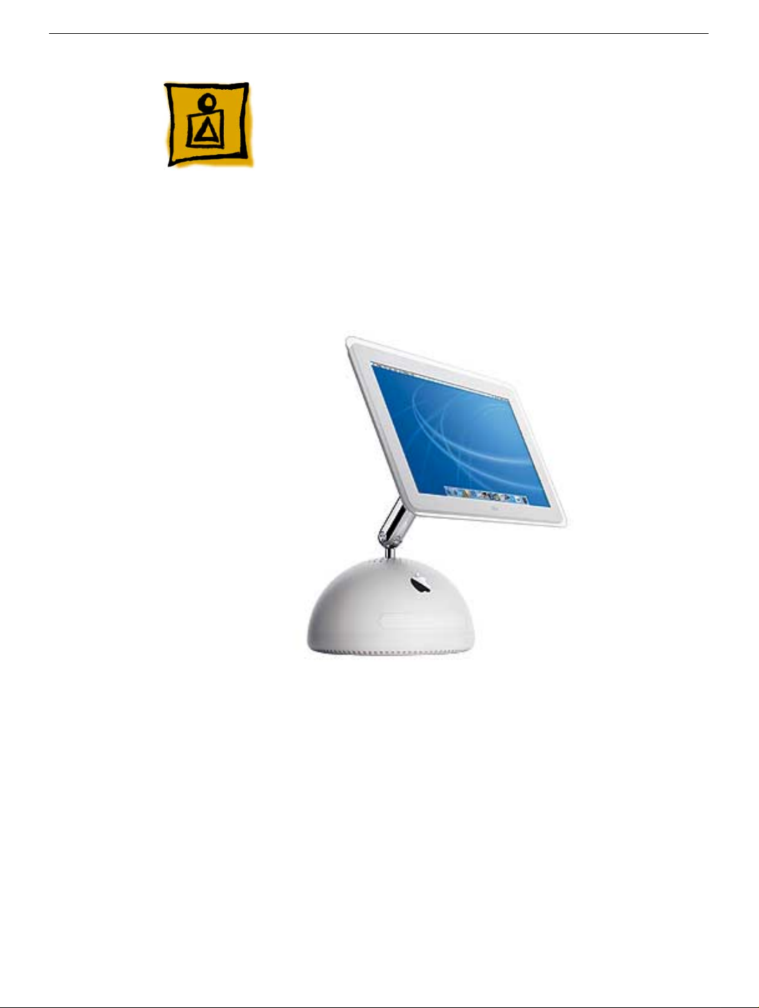
Overview
The iMac (USB 2.0) computers are powered by the PowerPC G4 processors. Two models
are available: the 17-inch widescreen LCD (1.25 GHZ) or the 15-inch LCD flat screen (1
GHz). The computer also includes 80GB hard drives, 256MB DDR333 SDRAM, two
FireWire 400 ports and three USB 2.0 ports. The 17-inch widescreen and the 15-inch flat
panel computers come with Mac OS X version 10.2.7 installed as the default system .
Overview
How to identify these models
Verify the processor speed. If the system is up and running, select “About this Mac” under
the Apple icon in the Finder. Or, select the “More Info” button on the “About this Mac”
window. Apple System Profiler opens and displays the machine speed under “Hardware
Overview.” The 15-inch iMac has a 1GHz PowerPC G4 processor and the 17-inch iMac
has a 1.25GHz PowerPC G4 processor.
iMac (USB 2.0) Basics - 1
Page 5

What’s New
New Features
Processor and speed —The microprocessor in the iMac (Flat Panel, USB 2.0) is a
PowerPC G4 with a clock speed of 1 GHz in the 15" configuration and a 1.25 GHz in the
17" configuration.
USB 2.0 ports — The computer has three USB 2.0 ports.
Memory — This computer comes with 256 MB of DDR333 SDRAM installed in an internal
standard 186-pin DIMM expansion slot, with a build-to-order options of 512 MB . A second
user-accessible slot accepts an SO-DIMM with up to 512 MB. The maximum total memory
is 1 GB.
System bus — The speed of the system bus is 167 MHz.
Graphics acceleration — The A GP 4X g raphics IC used is either an NVidia GeF orce4MX
or and NVidia GeForce FX5200 Ultra.
Video RAM — The video hardware includes either 32 MB or 64 MB of DDR SDRAM,
which supports 3D features and millions of colors in all resolutions.
External video monitor — The e xternal display connector supports mini-VGA, composite,
S-video monitors and projectors, and television sets. A video adapter with composite and
S-video connectors and a VGA-out adapter are available separately.
Bluetooth support (optional) — Bluetooth support is available as a build-to-order option
to enable short-range wireless connections between desktop and laptop computers and a
host of other peripheral devices.
2 - iMac (USB 2.0) Basics
What’s New
Page 6

Standard Configurations
Features 15-inch 17-inch
CPU and speed
System bus speed
Main memory
Display
Graphics IC
Graphics memory
Hard disk drive
Optical drive
External monitor
adapter
Communication features
1GHz PowerPC G4 1.25GHz PowerPC G4
167 MHz 167 MHz
256 MB SDRAM,
expandable up to 1 GB
15-inch flat panel 17-inch, wide-screen flat
NVIDIA GeForceMX NVIDIA GeForce FX
32 MB DDR RAM 64 MB DDR RAM
80 GB Ultra A TA-66 7200
rpm
Tray-load Combo drive Tray-load SuperDrive
Mini-VGA or S-video/
composite
10/100 Ethernet; 56K
V.92 fax modem
256 MB SDRAM,
expandable up to 1 GB
panel
5200 Ultra
80 GB Ultra A TA-66 7200
rpm
Mini-VGA or S-video/
composite
10/100 Ethernet; 56K
V.92 fax modem
What’s New
Wireless features
Optional 54 Mbps AirPort
Extreme Card; optional
internal Bluetooth
Optional 54 Mbps AirPort
Extreme Card; optional
internal Bluetooth
iMac (USB 2.0) Basics - 3
Page 7
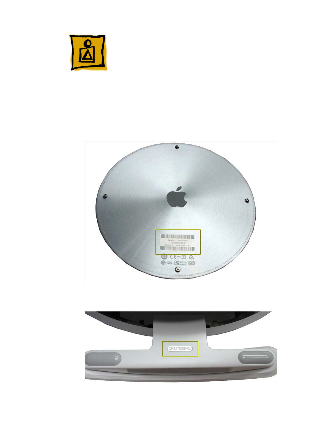
Serial Number Location
To identify a particular model of iMac (USB 2.0), check the computer’s serial number,
which lists the model’s configuration. The serial number is located on the bottom of the
computer, on the metal access plate, or on the inside of the optical drive door (bottom
photo).
4 - iMac (USB 2.0) Basics
Serial Number Location
Page 8

Serial Number Location
iMac (USB 2.0) Basics - 5
Page 9
Service Source
Take Apart
iMac (USB 2.0)
© 2003 Apple Computer, Inc. All rights reserved.
Page 10

General Information
Overview
The Take Apart chapter includes take apart procedures for both the 15" and 17" iMac
(USB 2.0) computers. If you are f amiliar with taking apart iMac (Flat Panel) computers, y ou
will find that the procedures for these newer models haven’t changed. The changes
consist of faster processors, f aster system bus , larger capacity hard drives, and three USB
2.0 ports.
New Procedures
The following Take Apart sections were updated:
• Display, Inverter, Back Cover, and the Neck Assembly
Tools
The following tools are recommended for the take apart procedures.
• The service stand (076-0898)
• Thermal paste (922-4757)
•
Torque driver, 17" LB (076-0899)
• 1.5 mm hex driver (for LCD bezel screws)
• #0 Phillips screwdriver)
• Torx screwdriver set (6, 8, 10, 15)
• Plastic flatblade screwdriver or stylus (922-5065)
• Needlenose pliers
• ESD wriststrap and mat
General Information
iMac (USB 2.0) Take Apart - 1
Page 11
Service Stand
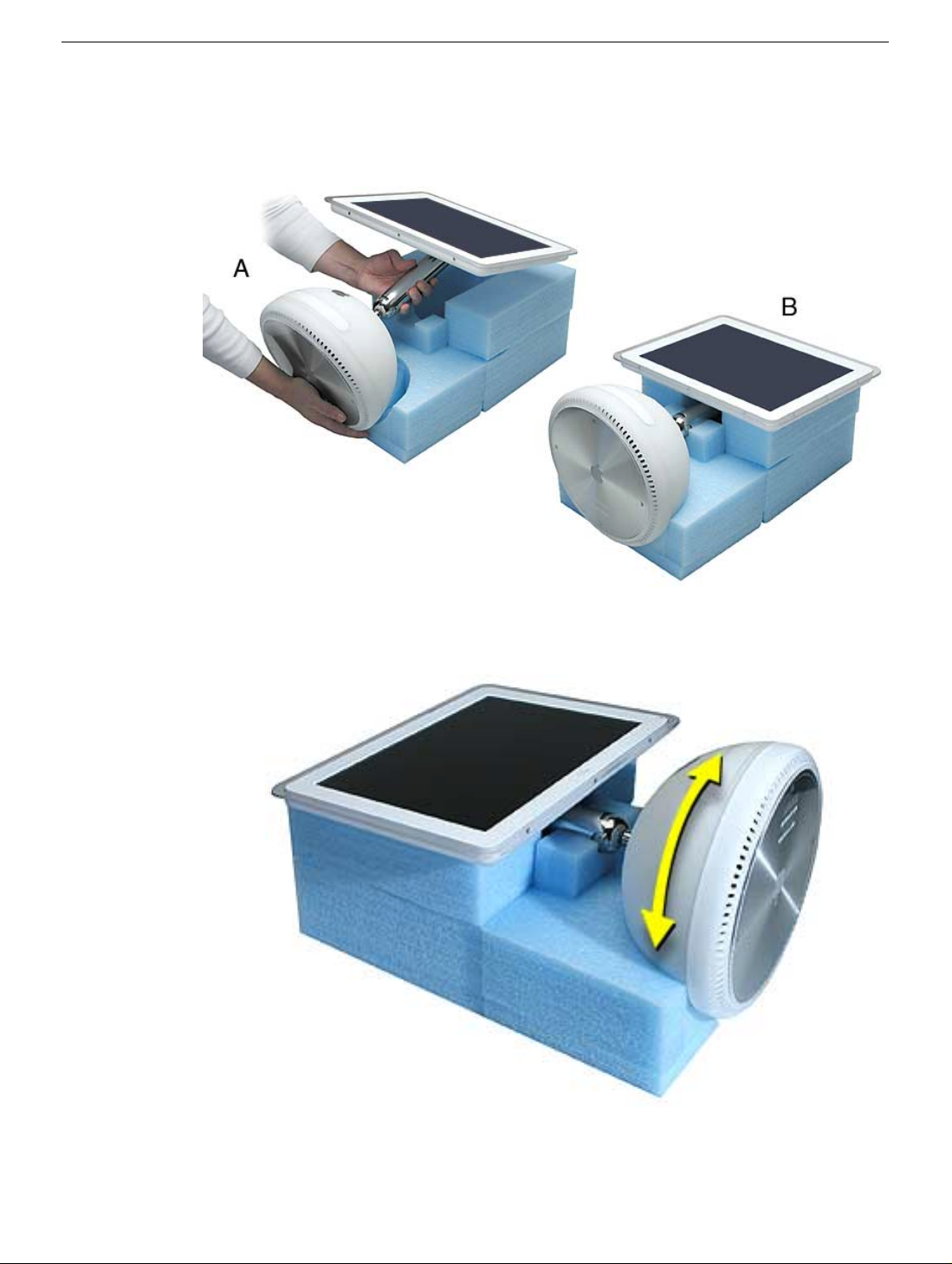
1. Support the computer by neck and the base (A). Gently position the computer in the
service stand with the flat panel facing up (B).
2. Note: The base of the computer can be rotated when servicing internal parts.
2 - iMac (USB 2.0) Take Apart
General Information
Page 12
User Access Plate
Tools
This procedure requires the following tools:
• Phillips #0 screwdriver
Part Location
User Access Plate
Preliminary Steps
Before you begin, do the following:
• Position the computer in the service stand.
iMac (USB 2.0) Take Apart - 3
Page 13
Procedure
1. Loosen the four captive screws on the access panel.
2. Remove the panel by grabbing onto two captive screws and lift the panel off the base.
4 - iMac (USB 2.0) Take Apart
User Access Plate
Page 14
AirPort Extreme Card
Tools
This procedure requires no tools.
Part Location
Preliminary Steps
Before you begin, do the following:
• Position the computer in the service stand.
• Remove the user access plate.
AirPort Extreme Card
iMac (USB 2.0) Take Apart - 5
Page 15
Procedure
1. Unplug all cables from the computer except the power cord.
Important: To avoid electrostatic discharge, always ground yourself by touching
2.
metal before you touch any parts or install any components inside the computer. To
avoid static electricity building back up in your body, do not walk around the room until
you have completed the installation and closed the computer.
3. Touch a metal surface inside the computer to ground yourself.
4. Unplug the power cord.
5. Pull the plastic tab on the AirPort Extreme card to remove it from the slot. Disconnect
the AirPort antenna from the card.
6 - iMac (USB 2.0) Take Apart
AirPort Extreme Card
Page 16
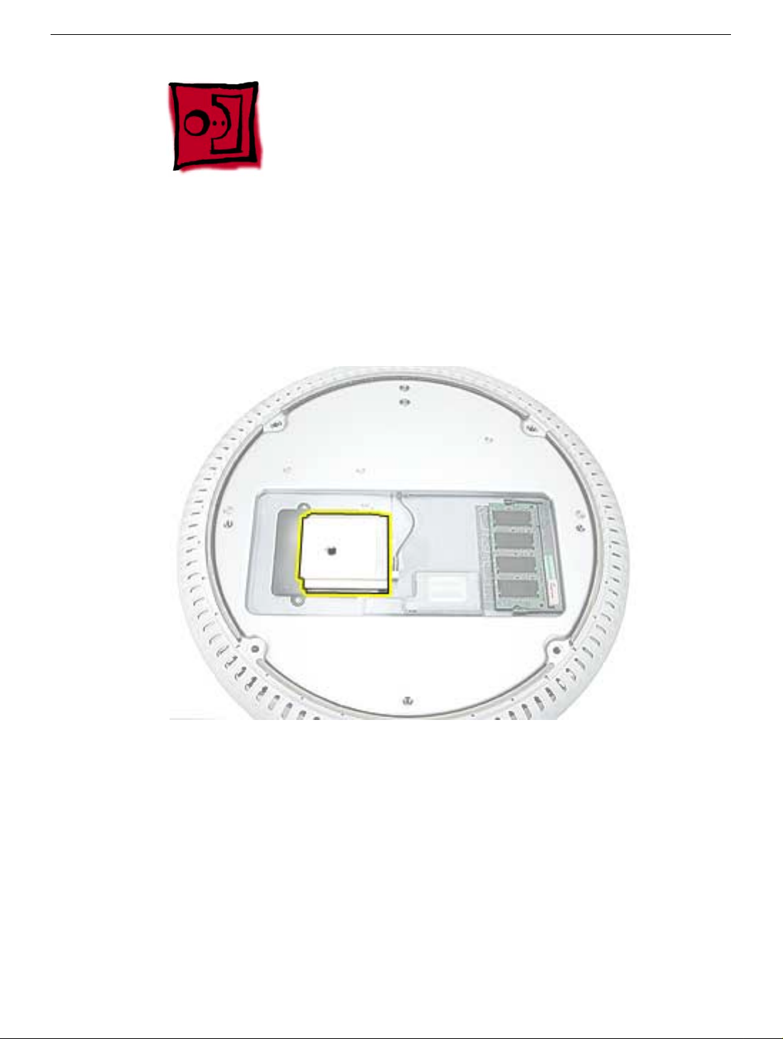
Memory, SO-DIMM (userinstallable)
Tools
No tools are required for this procedure.
Part Location
Preliminary Steps
Before you begin, do the following:
• Position the computer in the service stand.
• Remove the user access plate.
Note: DIMMs used in this slot should be a low-profile PC2700 (DDR333) SO-DIMM. Only
the SO-DIMM slot is accessible by the user.
Memory, SO-DIMM (user-installable)
iMac (USB 2.0) Take Apart - 7
Page 17
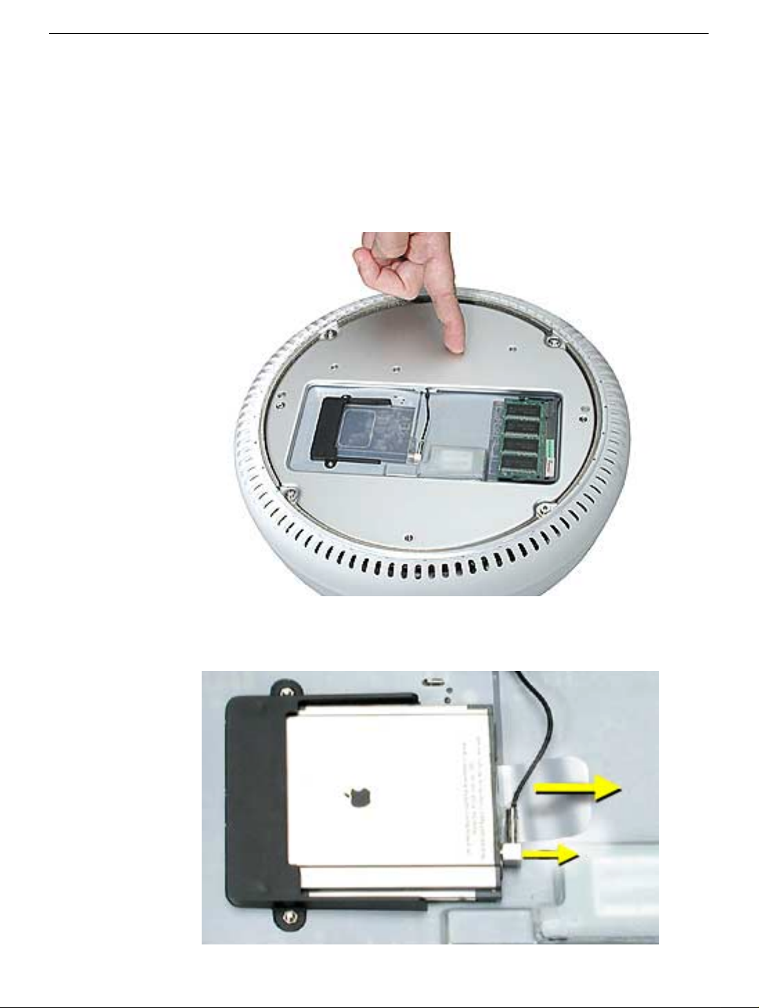
Procedure
1. Unplug all cables from the computer except the power cord.
Important: To avoid electrostatic discharge, always ground yourself by touching
2.
metal before you touch any parts or install any components inside the computer. To
avoid static electricity building back up in your body, do not walk around the room until
you have completed the installation and closed the computer.
3. Touch a metal surface inside the computer to ground yourself.
4. Unplug the power cord.
5. Release the memory by spreading apart the tabs in the expansion slot from the
notches in the card.
8 - iMac (USB 2.0) Take Apart
Memory, SO-DIMM (user-installable)
Page 18
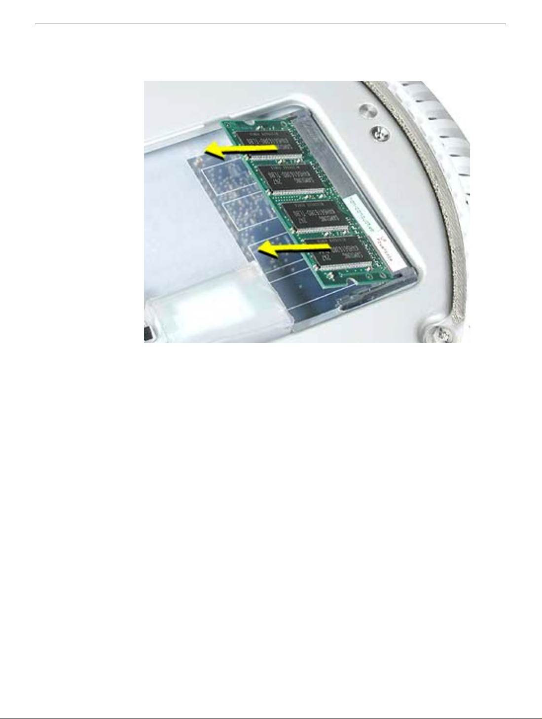
6. Allow the memory to pop up slightly, and pull it out of the memory slot.
Memory, SO-DIMM (user-installable)
iMac (USB 2.0) Take Apart - 9
Page 19
Bottom Housing
Tools
This procedure requires the following tools:
• Torx-15 screwdriver
Part Location
Preliminary Steps
Before you begin, do the following:
• Position the computer in the service stand.
• Remove the user access plate.
10 - iMac (USB 2.0) Take Apart
Bottom Housing
Page 20
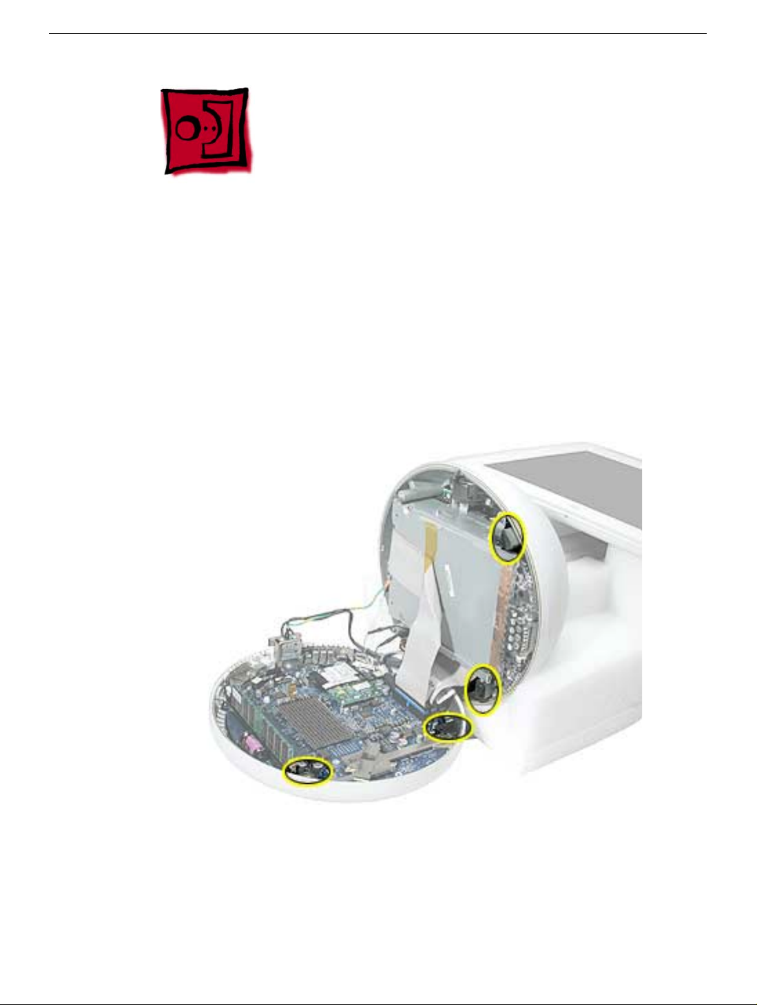
Procedure
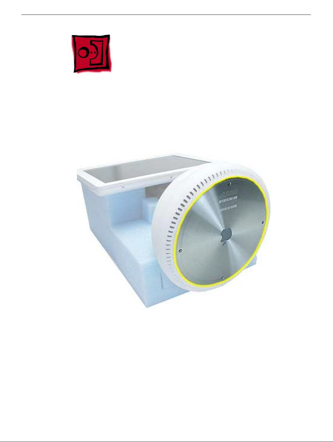
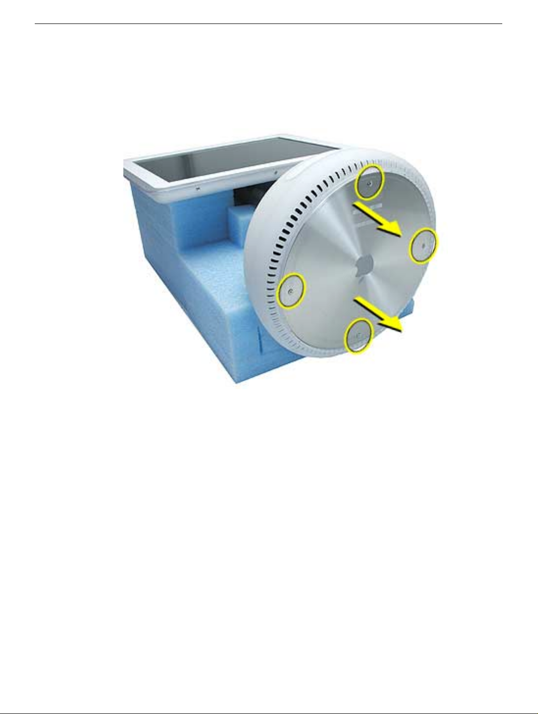
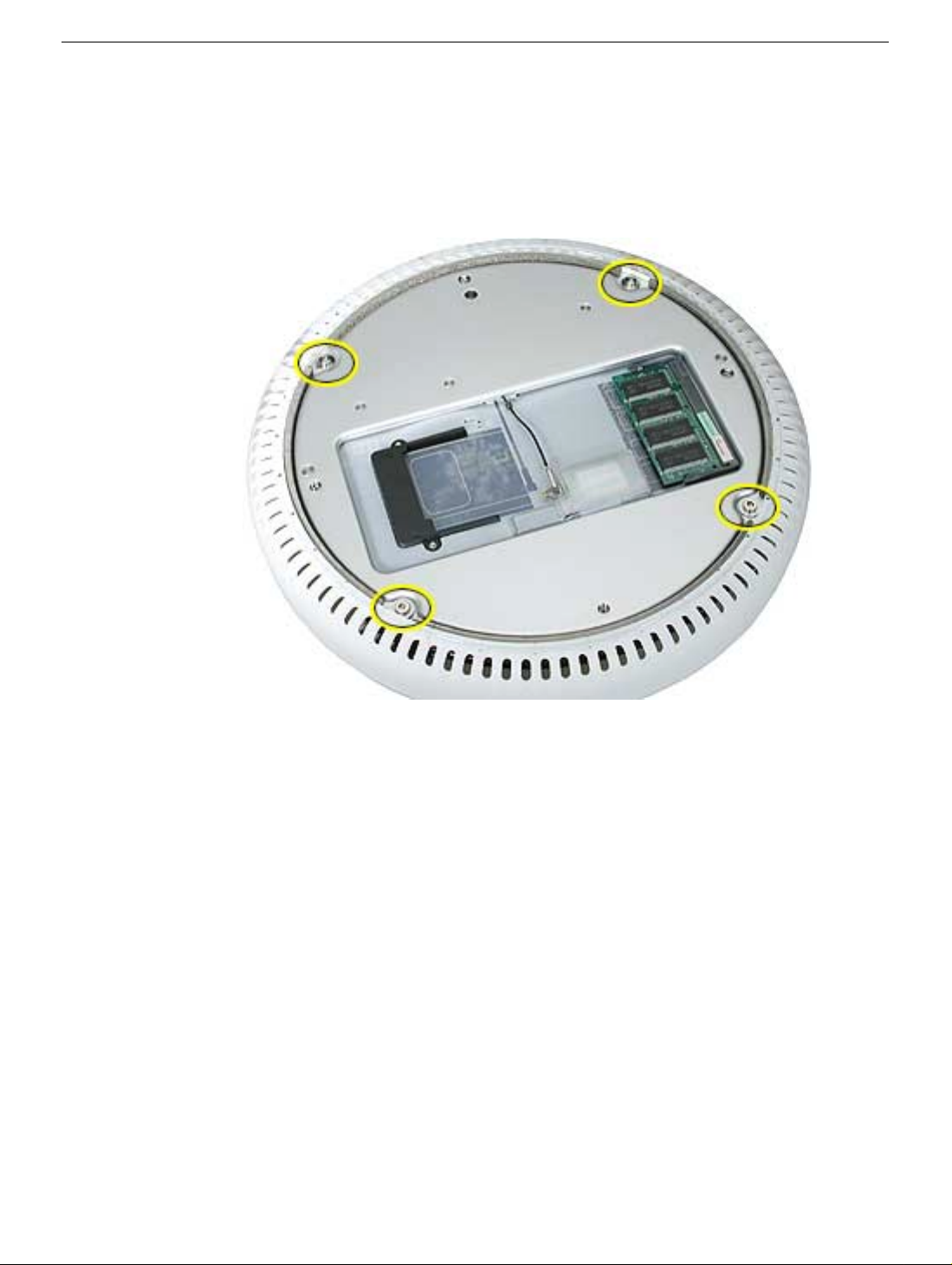
1. When opening the bottom housing, rotate the base so the optical drive door is on the
right. (This position is less stressful on the internal cables when the bottom is open).
2. Remove the four torx screws.
Replacement Note:
not have a torque driver, you will have to make sure these screws are tightened by hand
FIRMLY, BUT NOT FORCIBLY. Or, purchase the service tool (076-0899) in order to ensure
the thermal pipe is firmly mated with the top base. If the bottom housing is not securely
attached to the base in this fashion, the CPU may overheat and become damaged. For
more information, refer to “Thermal Paste Application’” in this chapter. Rotate the base so
that the optical drive door is on the right.
These torx screws must be tightened to at least 17 in.-lbs. If you do
iMac (USB 2.0) Take Apart - 11
Page 21
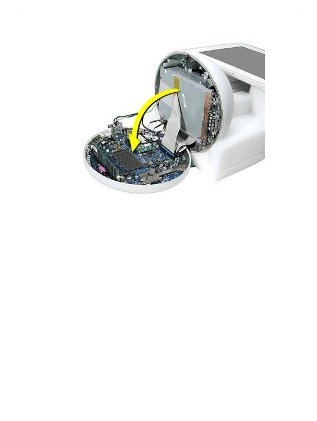
3. Gently open the bottom housing in the direction of the arrow. Disconnect the cables.
12 - iMac (USB 2.0) Take Apart
Page 22
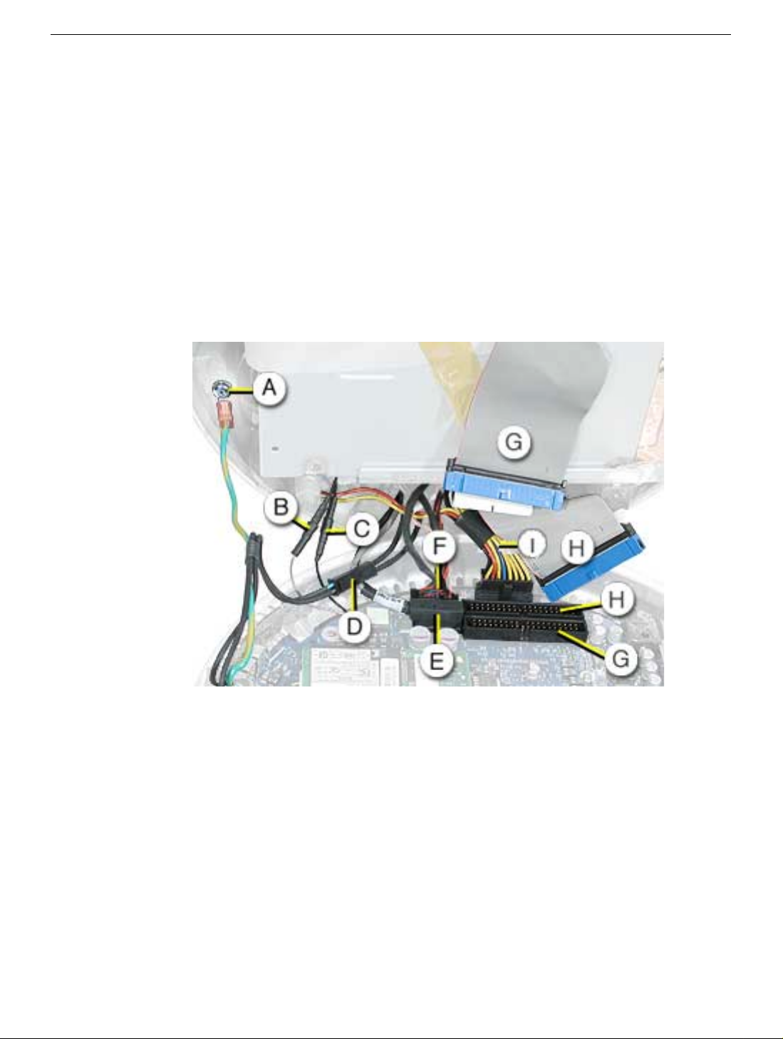
4. Disconnect the following:
C
D
E
A
Grounding screw
B
Bluetooth connector (if Bluetooth board is present, this will be connected)
AirPort connector
AC line filter connector
TMDS video connector
F Inverter, speaker, fan connector
G Optical cable and connector
H Hard drive cable and connector
I Power Supply connector
5. Set the bottom housing aside.
Warning: Whenever the bottom housing is opened for service, you must do two things:
1.You must clean the original thermal film from all thermal interface mating surfaces,
and reapply thermal paste to the mating surfaces on the thermal pipe.
2. You must tighten the four torx screws on the bottom housing to a minimum of 17
in.-lbs. Use a torque driver (service tool 076-0899) to ensure that the thermal pipe is
firmly mated with the top base. If you do not have a torque driver, you must make
sure the screws are tightened by hand FIRMLY, BUT NOT FORCIBLY.
Failure to follow these steps could cause the computer to overheat and
damage internal components.
Refer to the topic “Thermal Paste Application” for detailed information.
iMac (USB 2.0) Take Apart - 13
Page 23
Thermal Paste Application
Tools
This procedure requires the following tools:
• Plastic stylus or plastic spatula to remove the old thermal paste
• Plastic stylus or plastic spatula to spread the thermal paste
• Thermal paste (922-4757)
Part Location
14 - iMac (USB 2.0) Take Apart
Thermal Paste Application
Page 24
Procedure
1. Thoroughly clean the original thermal film from the mating surfaces (circled below) of
the bottom housing and thermal pipe. Use a plastic stylus to scrape the surfaces
clean. Note: Do not use an abrasive material or liquid cleaner.
2. Squeeze a ball of thermal paste onto the mating surfaces of the thermal pipe.
Thermal Paste Application
iMac (USB 2.0) Take Apart - 15
Page 25

3. Replace the bottom housing.
Warning: The bottom housing has four torx screws that must be tightened to at least
17 in.-lbs. Use a torque driver (service tool 076-0899) to ensure that the thermal pipe
is firmly mated with the top base. If you do not have a torque driver, you must make
sure the screws are tightened by hand FIRMLY, BUT NOT FORCIBLY.
Failure to apply the thermal paste as described in this procedure, and failure to
tighten the torx screws as directed, could cause the computer to overheat and
damage internal components.
Refer to the topic “Thermal Paste Application” for detailed information.
16 - iMac (USB 2.0) Take Apart
Thermal Paste Application
Page 26
RJ-11 Modem Filter Board
Tools
This procedure requires the following tools:
• Torx-6 screwdriver
Part Location
Preliminary Steps
Before you begin, do the following:
• Position the computer in the service stand.
• Remove the user access plate.
• Remove the bottom housing.
RJ-11 Modem Filter Board
iMac (USB 2.0) Take Apart - 17
Page 27
Procedure
1. Remove two screws and disconnect the cable from the modem.
2. Remove the RJ-11 board from the I/O port.
Warning: Whenever the bottom housing is opened for service, you must do two things:
1.You must clean the original thermal film from all thermal interface mating surfaces,
and reapply thermal paste to the mating surfaces on the thermal pipe.
2. You must tighten the four torx screws on the bottom housing to a minimum of 17
in.-lbs. Use a torque driver (service tool 076-0899) to ensure that the thermal pipe is
firmly mated with the top base. If you do not have a torque driver, you must make
sure the screws are tightened by hand FIRMLY, BUT NOT FORCIBLY.
Failure to follow these steps could cause the computer to overheat and
damage internal components.
Refer to the topic “Thermal Paste Application” for detailed information.
18 - iMac (USB 2.0) Take Apart
RJ-11 Modem Filter Board
Page 28
Modem
Tools
This procedure requires the following tools:
• Torx-8 screwdriver
Part Location
Modem
Preliminary Steps
Before you begin, do the following:
• Position the computer in the service stand.
• Remove the user access plate.
• Remove the bottom housing.
iMac (USB 2.0) Take Apart - 19
Page 29
Procedure
1. Remove two screws and disconnect the cable.
2. Lift the modem board from the connector on the logic board.
Warning: Whenever the bottom housing is opened for service, you must do two things:
1.You must clean the original thermal film from all thermal interface mating surfaces,
and reapply thermal paste to the mating surfaces on the thermal pipe.
2. You must tighten the four torx screws on the bottom housing to a minimum of 17
in.-lbs. Use a torque driver (service tool 076-0899) to ensure that the thermal pipe is
firmly mated with the top base. If you do not have a torque driver, you must make
sure the screws are tightened by hand FIRMLY, BUT NOT FORCIBLY.
Failure to follow these steps could cause the computer to overheat and
damage internal components.
Refer to the topic “Thermal Paste Application” for detailed information.
20 - iMac (USB 2.0) Take Apart
Modem
Page 30
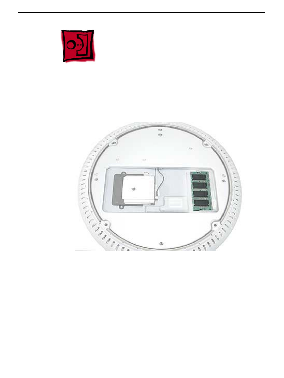
Memory (factory-installed)
Tools
This procedure requires the following tools:
• No tools are required
Part Location
Preliminary Steps
Before you begin, do the following:
• Position the computer in the service stand.
• Remove the user access plate.
• Remove the bottom housing.
Memory (factory-installed)
iMac (USB 2.0) Take Apart - 21
Page 31

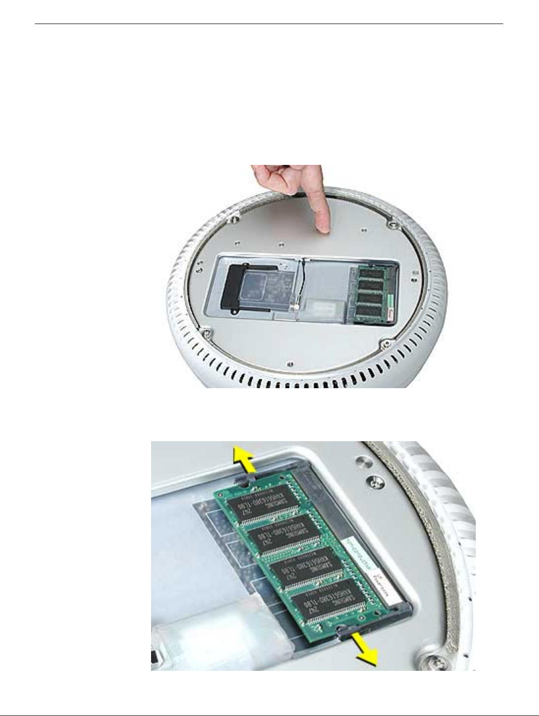
Procedure
1. Push down on the ejector tabs to release the memory module.
2. Pull the memory up and out of the slot. Important: Make sure that the memory
installed on the logic board is compatible with the system. The computer accepts
double-data rate (DDR) SDRAM DIMMs. DIMMs used in this slot must fit the following
specification: PC2700 SDRAM DDR333 DIMMs for 167 MHz systems.
Warning: Whenever the bottom housing is opened for service, you must do two things:
1.You must clean the original thermal film from all thermal interface mating surfaces,
and reapply thermal paste to the mating surfaces on the thermal pipe.
2. You must tighten the four torx screws on the bottom housing to a minimum of 17
in.-lbs. Use a torque driver (service tool 076-0899) to ensure that the thermal pipe is
firmly mated with the top base. If you do not have a torque driver, you must make
sure the screws are tightened by hand FIRMLY, BUT NOT FORCIBLY.
Failure to follow these steps could cause the computer to overheat and
damage internal components.
Refer to the topic “Thermal Paste Application” for detailed information.
22 - iMac (USB 2.0) Take Apart
Memory (factory-installed)
Page 32

Battery
Tools
This procedure requires the following tools:
• No tools are required
Part Location
Battery
Preliminary Steps
Before you begin, do the following:
• Position the computer in the service stand.
• Remove the user access plate.
• Remove the bottom housing.
iMac (USB 2.0) Take Apart - 23
Page 33

Procedure
1. Using a flatblade screwdriver, gently pry the battery from the battery holder.
Warning: Whenever the bottom housing is opened for service, you must do two things:
1.You must clean the original thermal film from all thermal interface mating surfaces,
and reapply thermal paste to the mating surfaces on the thermal pipe.
2. You must tighten the four torx screws on the bottom housing to a minimum of 17
in.-lbs. Use a torque driver (service tool 076-0899) to ensure that the thermal pipe is
firmly mated with the top base. If you do not have a torque driver, you must make
sure the screws are tightened by hand FIRMLY, BUT NOT FORCIBLY.
Failure to follow these steps could cause the computer to overheat and
damage internal components.
Refer to the topic “Thermal Paste Application” for detailed information.
24 - iMac (USB 2.0) Take Apart
Battery
Page 34

Logic Board
Tools
This procedure requires the following tools:
• Phillips #2 screwdriver (for the plastic screw)
• Torx-15 screwdriver
Part Location
Note: The battery, RJ-11 board, AirPort Extreme card, modem, I/O port covers, memory
(on the top and the bottom of the logic board), Bluetooth board and the Bluetooth
extension cable need to be removed from the logic board before returning the board to
Apple for service.
Logic Board
Preliminary Steps
Before you begin, do the following:
• Position the computer in the service stand.
• Remove the user access plate.
• Remove the bottom housing.
• Remove the RJ-11 board.
iMac (USB 2.0) Take Apart - 25
Page 35

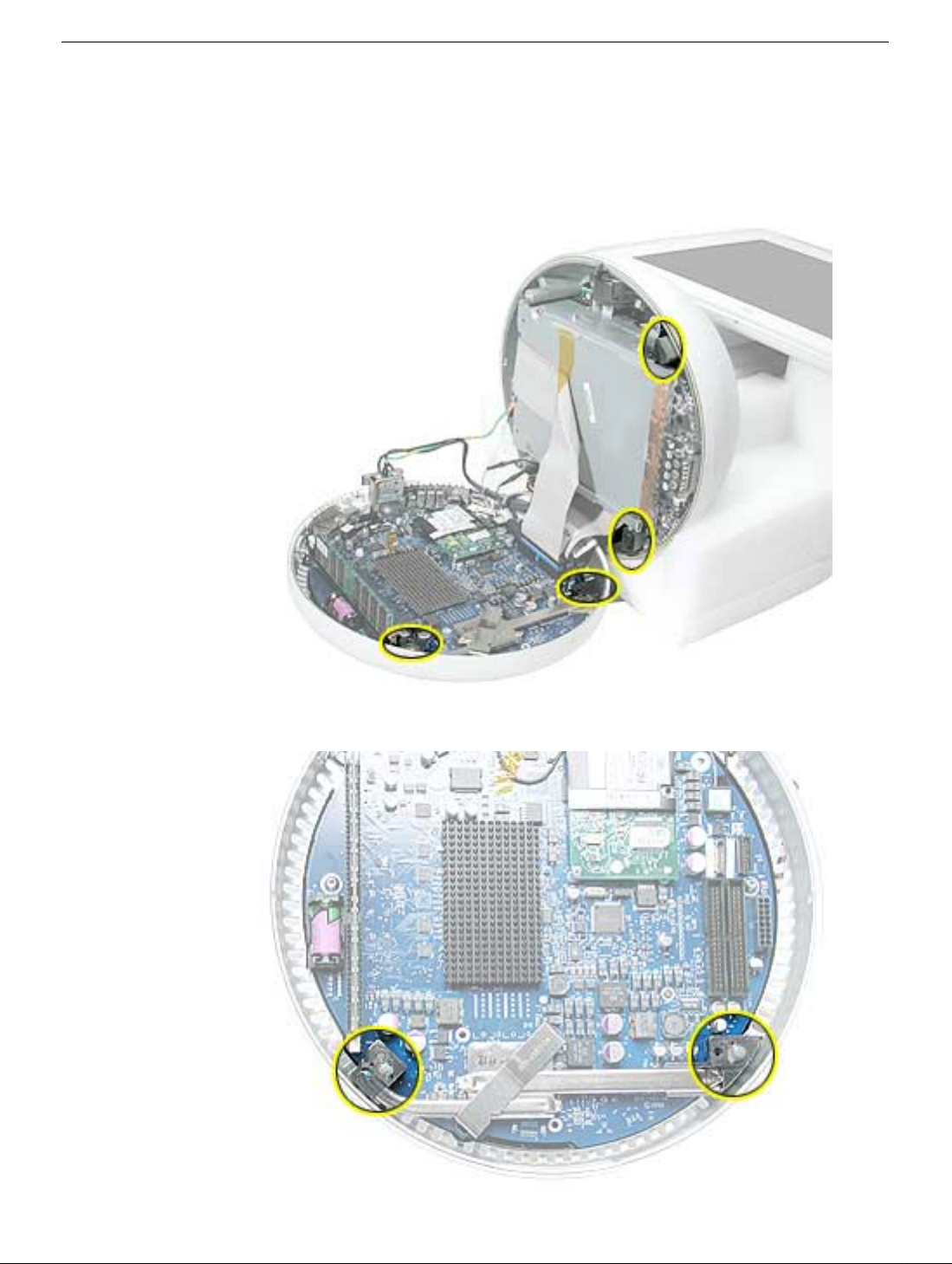
Procedure
1. Remove the three torx screws (metal) and one plastic screw.
26 - iMac (USB 2.0) Take Apart
Logic Board
Page 36

2. Grab the logic board by the battery retainer and the hard drive connector. Lift the
board slightly and pull back to release the board from the bottom housing and I/O
ports. Note: The I/O port covers may come out with the logic board when it’s
removed.
3. Remove the I/O port covers from the logic board.
Warning: Whenever the logic board is separated from the bottom housing, you must
install new thermal pads to three surfaces on the bottom housing. Failure to apply these
pads whenever the logic board is separated from the bottom housing could cause these
parts to overheat and could damage internal components.
Note: AFTER installing new thermal pads, if you must briefly re-separate the logic board
from the housing, it is OK to retain the same, new pads as long as they are not handled
excessively. Refer to “Thermal Pad Installation” in this chapter for detailed information.
Warning: Whenever the bottom housing is opened for service, you must do two things:
1.You must clean the original thermal film from all thermal interface mating surfaces,
and reapply thermal paste to the mating surfaces on the thermal pipe.
2. You must tighten the four torx screws on the bottom housing to a minimum of 17
in.-lbs. Use a torque driver (service tool 076-0899) to ensure that the thermal pipe is
firmly mated with the top base. If you do not have a torque driver, you must make
sure the screws are tightened by hand FIRMLY, BUT NOT FORCIBLY.
Failure to follow these steps could cause the computer to overheat and
damage internal components.
Refer to the topic “Thermal Paste Application” for detailed information.
Logic Board
iMac (USB 2.0) Take Apart - 27
Page 37

Bluetooth Board and Cable
Tools
This procedure requires the following tools:
• Phillips #2 jeweler’s screwdriver
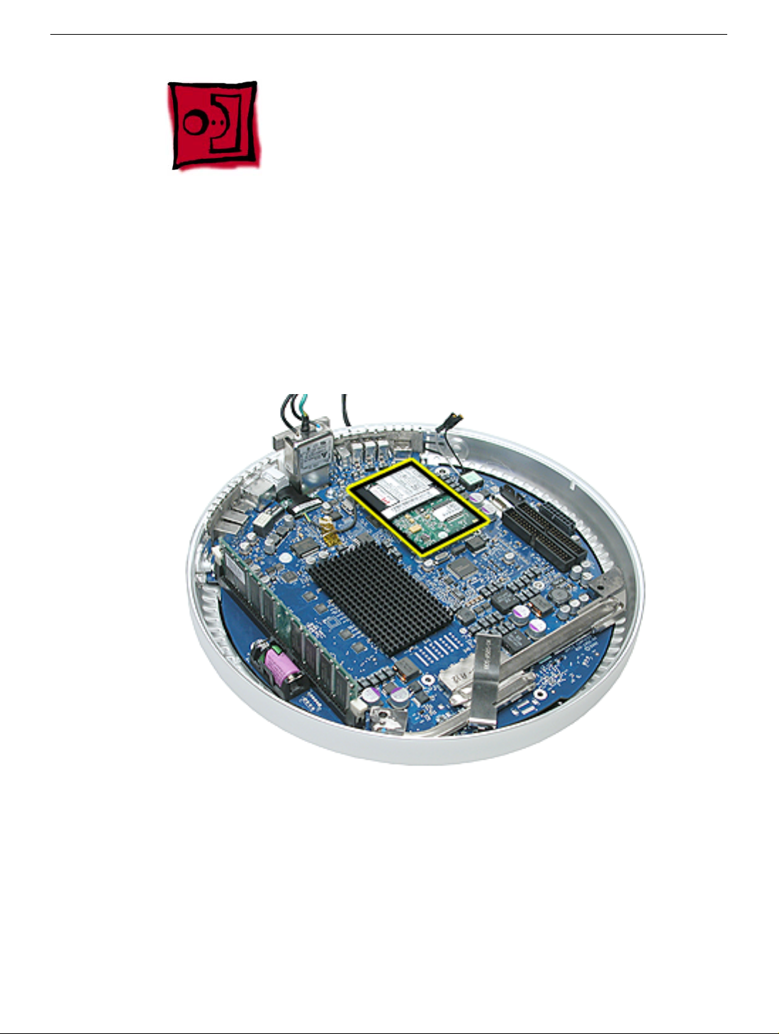
Part Location
Preliminary Steps
Before you begin, do the following:
• Position the computer in the service stand.
• Remove the user access plate.
• Remove the bottom housing.
• Remove the RJ-11 board.
• Remove the logic board.
28 - iMac (USB 2.0) Take Apart
Bluetooth Board and Cable
Page 38

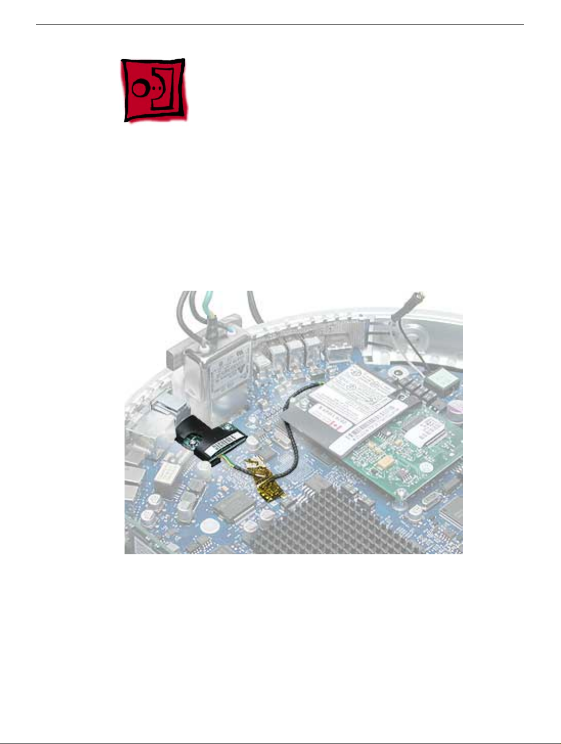
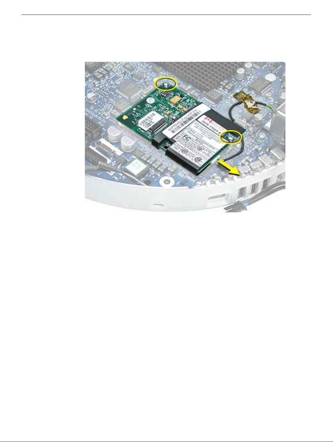
Procedure
1. Ground yourself. Remove the AirPort Extreme card and SO-DIMM memory (if
present).
2. Remove the logic board protective cover to access the Bluetooth board
Bluetooth Board and Cable
iMac (USB 2.0) Take Apart - 29
Page 39

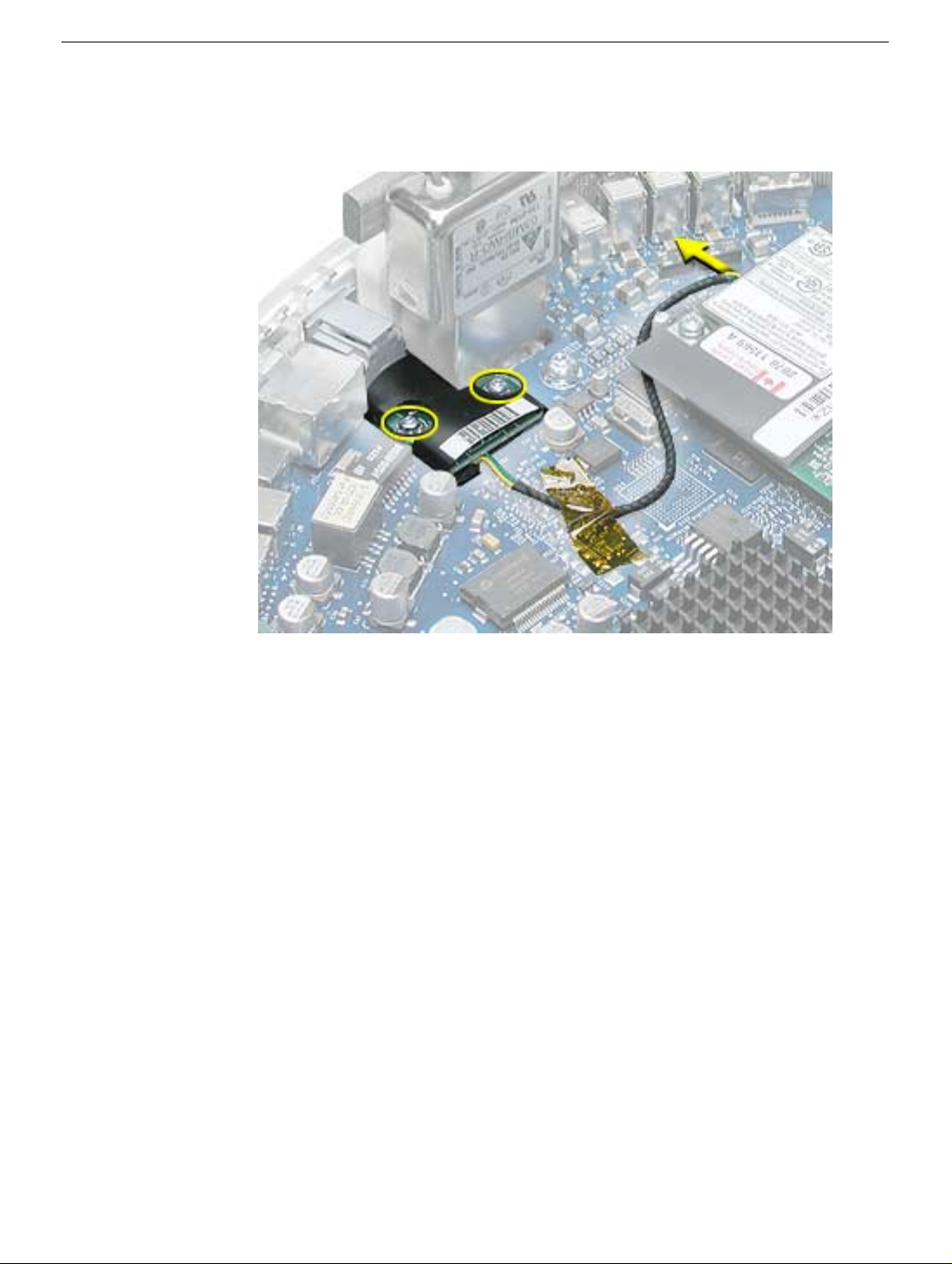
3. Remove the two screws (circled below) on the Bluetooth board.
4. Peel the Kapton tape off the Bluetooth extension cable. Disconnect the extension
cable from the Bluetooth board. Note: The Bluetooth wireless extension cable is a
separate service part from the Bluetooth board.
5. Lift the Bluetooth board from the connector on the logic board.
Warning: Whenever the logic board is separated from the bottom housing, you must
install new thermal pads to three surfaces on the bottom housing. Failure to apply these
pads whenever the logic board is separated from the bottom housing could cause these
parts to overheat and could damage internal components.
Note: AFTER installing new thermal pads, if you must briefly re-separate the logic board
from the housing, it is OK to retain the same, new pads as long as they are not handled
excessively. Refer to “Thermal Pad Installation” in this chapter for detailed information.
Warning: Whenever the bottom housing is opened for service, you must do two things:
1.You must clean the original thermal film from all thermal interface mating surfaces,
and reapply thermal paste to the mating surfaces on the thermal pipe.
2. You must tighten the four torx screws on the bottom housing to a minimum of 17
in.-lbs. Use a torque driver (service tool 076-0899) to ensure that the thermal pipe is
firmly mated with the top base. If you do not have a torque driver, you must make
sure the screws are tightened by hand FIRMLY, BUT NOT FORCIBLY.
Failure to follow these steps could cause the computer to overheat and
damage internal components.
Refer to the topic “Thermal Paste Application” for detailed information.
30 - iMac (USB 2.0) Take Apart
Bluetooth Board and Cable
Page 40

I/O Port Covers
Tools
This procedure requires the following tools:
• No tools are required
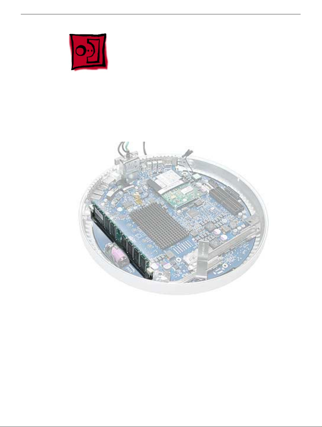
Part Location
I/O Port Covers
Preliminary Steps
Before you begin, do the following:
• Position the computer in the service stand.
• Remove the user access plate.
• Remove the bottom housing.
• Remove the RJ-11 board
• Remove the logic board.
iMac (USB 2.0) Take Apart - 31
Page 41

Procedure
1. Gently pull the I/O port covers off the logic board.
Warning: Whenever the bottom housing is opened for service, you must do two things:
1.You must clean the original thermal film from all thermal interface mating surfaces,
and reapply thermal paste to the mating surfaces on the thermal pipe.
2. You must tighten the four torx screws on the bottom housing to a minimum of 17
in.-lbs. Use a torque driver (service tool 076-0899) to ensure that the thermal pipe is
firmly mated with the top base. If you do not have a torque driver, you must make
sure the screws are tightened by hand FIRMLY, BUT NOT FORCIBLY.
Failure to follow these steps could cause the computer to overheat and
damage internal components.
Refer to the topic “Thermal Paste Application” for detailed information.
Warning: Whenever the logic board is separated from the bottom housing, you must
install new thermal pads to three surfaces on the bottom housing. Failure to apply these
pads whenever the logic board is separated from the bottom housing could cause these
parts to overheat and could damage internal components.
Note: AFTER installing new thermal pads, if you must briefly re-separate the logic board
from the housing, it is OK to retain the same, new pads as long as they are not handled
excessively. Refer to “Thermal Pad Installation” in this chapter for detailed information.
32 - iMac (USB 2.0) Take Apart
I/O Port Covers
Page 42

AirPort Antenna Extension Cable
Tools
This procedure requires the following tools:
• No tools are required
Part Location
Preliminary Steps
Before you begin, do the following:
• Position the computer in the service stand.
• Remove the user access plate.
• Remove the bottom housing.
• Remove the RJ-11 board
• Remove the logic board.
AirPort Antenna Extension Cable
iMac (USB 2.0) Take Apart - 33
Page 43

Procedure
1. Release the extension cable from the plastic cable clips to remove the cable from the
bottom housing.
Replacement Note: Be careful not to pinch the antenna extension cable when
replacing it.
Warning: Whenever the bottom housing is opened for service, you must do two things:
1.You must clean the original thermal film from all thermal interface mating surfaces,
and reapply thermal paste to the mating surfaces on the thermal pipe.
2. You must tighten the four torx screws on the bottom housing to a minimum of 17
in.-lbs. Use a torque driver (service tool 076-0899) to ensure that the thermal pipe is
firmly mated with the top base. If you do not have a torque driver, you must make
sure the screws are tightened by hand FIRMLY, BUT NOT FORCIBLY.
Failure to follow these steps could cause the computer to overheat and
damage internal components.
Refer to the topic “Thermal Paste Application” for detailed information.
Warning: Whenever the logic board is separated from the bottom housing, you must
install new thermal pads to three surfaces on the bottom housing. Failure to apply these
pads whenever the logic board is separated from the bottom housing could cause these
parts to overheat and could damage internal components.
Note: AFTER installing new thermal pads, if you must briefly re-separate the logic board
from the housing, it is OK to retain the same, new pads as long as they are not handled
excessively. Refer to “Thermal Pad Installation” in this chapter for detailed information.
34 - iMac (USB 2.0) Take Apart
AirPort Antenna Extension Cable
Page 44

Thermal Pad Installation
Tools
• No tools are required.
• Thermal pad kit (076-0925)
Part Location
Warning: Whenever the logic board is separated from the bottom housing, you must
install new thermal pads to two surfaces on the bottom housing. Failure to apply these
pads whenever the logic board is separated from the bottom housing could cause these
parts to overheat and could damage internal components.
Note: AFTER installing new thermal pads, if you must briefly re-separate the logic board
from the housing, it is OK to retain the same, new pads as long as they are not handled
excessively.
Thermal Pad Installation
iMac (USB 2.0) Take Apart - 35
Page 45

Procedure
1. Remove the old thermal pads from the bottom housing. Note: If you don’t see the two
thermal pads on the bottom housing, check the under side of the logic board. The
thermal pads may stick to the logic board. Always remove the old thermal pads, and
install new pads if you are taking the unit apart to this level.
2. Using the thermal pad kit, remove the clear protective backing from the new thermal
pads.
3. Place the new thermal pads on the bottom housing. Press do wn on the blue protectiv e
backing to make sure the thermal pad has even contact with the bottom housing.
There should be no air pockets.
4. Remove the blue protective backing from the new thermal pad. Note: Avoid
unnecessary contact with either side of the thermal pad as dirt and body oils reduce
the thermal pad's conductivity.
5. Slide the logic board back into the bottom housing (make sure the I/O port covers are
on the logic board).
36 - iMac (USB 2.0) Take Apart
Thermal Pad Installation
Page 46

AC Line Filter
Tools
This procedure requires the following tools:
• Torx-10 screwdriver
Part Location
AC Line Filter
Preliminary Steps
Before you begin, do the following:
• Position the computer in the service stand.
• Remove the user access plate.
• Remove the bottom housing.
• Remove the RJ-11 board.
• Remove the logic board.
iMac (USB 2.0) Take Apart - 37
Page 47

Procedure
1. Peel the black insulator on the bottom housing back to access the AC line filter
screws.
2. Remove two screws and lift the AC line filter from the bottom housing. Note: The port
plug may fall out of the AC filter port when you remove the AC line filter. Replace the
plug into the opening on the bottom housing before reinstalling the AC line filter.
38 - iMac (USB 2.0) Take Apart
AC Line Filter
Page 48

Warning: Whenever the bottom housing is opened for service, you must do two things:
1.You must clean the original thermal film from all thermal interface mating surfaces,
and reapply thermal paste to the mating surfaces on the thermal pipe.
2. You must tighten the four torx screws on the bottom housing to a minimum of 17
in.-lbs. Use a torque driver (service tool 076-0899) to ensure that the thermal pipe is
firmly mated with the top base. If you do not have a torque driver, you must make
sure the screws are tightened by hand FIRMLY, BUT NOT FORCIBLY.
Failure to follow these steps could cause the computer to overheat and
damage internal components.
Refer to the topic “Thermal Paste Application” for detailed information.
Warning: Whenever the logic board is separated from the bottom housing, you must
install new thermal pads to three surfaces on the bottom housing. Failure to apply these
pads whenever the logic board is separated from the bottom housing could cause these
parts to overheat and could damage internal components.
Note: AFTER installing new thermal pads, if you must briefly re-separate the logic board
from the housing, it is OK to retain the same, new pads as long as they are not handled
excessively. Refer to “Thermal Pad Installation” in this chapter for detailed information.
AC Line Filter
iMac (USB 2.0) Take Apart - 39
Page 49

Drive Carrier Assembly (Optical and Hard Drive)
Tools
This procedure requires the following tools:
• Torx-10 screwdriver
Part Location
Preliminary Steps
Before you begin, do the following:
• Position the computer in the service stand with the door facing up.
• Remove the user access plate.
• Remove the bottom housing.
40 - iMac (USB 2.0) Take Apart
Drive Carrier Assembly (Optical and Hard Drive)
Page 50

Procedure
1. Rotate the base unit so the optical drive door is facing to the right.
2. Remove six screws; two on the EMI shield (with copper tape) and four attaching the
drive to the Faraday cage (chassis). Carefully lift the shield and copper tape off the
drive. Replacement Note: When replacing the drive EMI shield, be sure to use the
two shorter screws.
Drive Carrier Assembly (Optical and Hard Drive)
iMac (USB 2.0) Take Apart - 41
Page 51

3. Remove the Airport and Bluetooth antennas from the plastic clip on the side of the
drive carrier.
42 - iMac (USB 2.0) Take Apart
Drive Carrier Assembly (Optical and Hard Drive)
Page 52

4. Grasp the carrier by the top and bottom edges. Wiggle the drive carrier out of the
chassis pulling the carrier in the direction of the arrow. Note: The carrier fits snugly
into the chassis.
5. Disconnect the two power cables; one attaches to the optical drive and the other
attaches to the hard drive.
Drive Carrier Assembly (Optical and Hard Drive)
iMac (USB 2.0) Take Apart - 43
Page 53

6. To remove the hard drive from the carrier, peel the white wrapper up to access the
screws (two on each side). Remove the screws, disconnect the data cable, and
remove the hard drive out of the carrier.
7. To remove the optical drive, remove four screws (shown by dashed lines), disconnect
the optical drive data cable (see lower arrow), and slide the optical drive out of the
carrier.
44 - iMac (USB 2.0) Take Apart
Drive Carrier Assembly (Optical and Hard Drive)
Page 54

Warning: Whenever the bottom housing is opened for service, you must do two things:
1.You must clean the original thermal film from all thermal interface mating surfaces,
and reapply thermal paste to the mating surfaces on the thermal pipe.
2. You must tighten the four torx screws on the bottom housing to a minimum of 17
in.-lbs. Use a torque driver (service tool 076-0899) to ensure that the thermal pipe is
firmly mated with the top base. If you do not have a torque driver, you must make
sure the screws are tightened by hand FIRMLY, BUT NOT FORCIBLY.
Failure to follow these steps could cause the computer to overheat and
damage internal components.
Refer to the topic “Thermal Paste Application” for detailed information.
iMac (USB 2.0) Take Apart - 45
Page 55

Power Supply
Tools
This procedure requires the following tools:
• Torx-10 screwdriver
Part Location
Preliminary Steps
Before you begin, do the following:
• Position the computer in the service stand and rotate the door to the right.
• Remove the user access plate.
• Remove the bottom housing.
• Remove the drive carrier assembly.
46 - iMac (USB 2.0) Take Apart
Power Supply
Page 56

Procedure
1. Remove the two power supply screws circled below.
Power Supply
iMac (USB 2.0) Take Apart - 47
Page 57

2. Open the optical drive door as shown. Support the metal plate and power supply as
you remove the four screws.
Important: The two screws near the door hinge are shorter than the other power
supply screws. Failure to replace the shorter screws into their correct location will
scratch the top housing. See step 4, Replacement Note.
48 - iMac (USB 2.0) Take Apart
Power Supply
Page 58

3. Lift the power supply and metal shield out of the chassis (Faraday cage).
4. Replacement Note: When replacing the metal shield (see picture above) that sits on
top of the power supply, install the two shorter screws near the optical door. If the
longer screws are installed by mistake, the screws will scratch the inside of the
housing (circled below).
Power Supply
iMac (USB 2.0) Take Apart - 49
Page 59

Warning: Whenever the bottom housing is opened for service, you must do two things:
1.You must clean the original thermal film from all thermal interface mating surfaces,
and reapply thermal paste to the mating surfaces on the thermal pipe.
2. You must tighten the four torx screws on the bottom housing to a minimum of 17
in.-lbs. Use a torque driver (service tool 076-0899) to ensure that the thermal pipe is
firmly mated with the top base. If you do not have a torque driver, you must make
sure the screws are tightened by hand FIRMLY, BUT NOT FORCIBLY.
Failure to follow these steps could cause the computer to overheat and
damage internal components.
Refer to the topic “Thermal Paste Application” for detailed information.
50 - iMac (USB 2.0) Take Apart
Power Supply
Page 60

Optical Drive Door
Tools
This procedure requires the following tools:
• Torx-10 screwdriver
• Needlenose pliers
Part Location
Optical Drive Door
Preliminary Steps
Before you begin, do the following:
• Position the computer in the service stand.
• Remove the user access plate.
• Remove the bottom housing.
• Remove the drive carrier assembly.
iMac (USB 2.0) Take Apart - 51
Page 61

Procedure
1. Remove four screws on the power supply shield. Set the shield aside.
Important: The two screws near the door hinge are shorter than the other power
supply screws. Failure to replace the shorter screws to their correct location will
scratch the top housing. See the Power Supply topic, step 4, Replacement Note, for a
picture of what happens when the wrong screws are inserted in the wrong location.
52 - iMac (USB 2.0) Take Apart
Optical Drive Door
Page 62

2. Slide the optical door guide off the chassis and the door hinge tabs (circled).
3. Carefully remove the two door springs with a needlenose pliers.
Optical Drive Door
iMac (USB 2.0) Take Apart - 53
Page 63

4. Remove the door hinge screws.
5. Open the door.
54 - iMac (USB 2.0) Take Apart
Optical Drive Door
Page 64

6. Slide the door and hinge off the chassis.
Warning: Whenever the bottom housing is opened for service, you must do two things:
1.You must clean the original thermal film from all thermal interface mating surfaces,
and reapply thermal paste to the mating surfaces on the thermal pipe.
2. You must tighten the four torx screws on the bottom housing to a minimum of 17
in.-lbs. Use a torque driver (service tool 076-0899) to ensure that the thermal pipe is
firmly mated with the top base. If you do not have a torque driver, you must make
sure the screws are tightened by hand FIRMLY, BUT NOT FORCIBLY.
Failure to follow these steps could cause the computer to overheat and
damage internal components.
Refer to the topic “Thermal Paste Application” for detailed information.
Optical Drive Door
iMac (USB 2.0) Take Apart - 55
Page 65

Speaker, Internal
Tools
This procedure requires the following tools:
• Torx-10 screwdriver
Part Location
Preliminary Steps
Before you begin, do the following:
• Position the computer in the service stand.
• Remove the user access plate.
• Remove the bottom housing.
• Remove the drive carrier assembly.
56 - iMac (USB 2.0) Take Apart
Speaker, Internal
Page 66

Procedure
1. Loosen the two screws enough to slide the speaker off the metal posts. Disconnect
the speaker cable.
Warning: Whenever the bottom housing is opened for service, you must do two things:
1.You must clean the original thermal film from all thermal interface mating surfaces,
and reapply thermal paste to the mating surfaces on the thermal pipe.
2. You must tighten the four torx screws on the bottom housing to a minimum of 17
in.-lbs. Use a torque driver (service tool 076-0899) to ensure that the thermal pipe is
firmly mated with the top base. If you do not have a torque driver, you must make
sure the screws are tightened by hand FIRMLY, BUT NOT FORCIBLY.
Failure to follow these steps could cause the computer to overheat and
damage internal components.
Refer to the topic “Thermal Paste Application” for detailed information.
Speaker, Internal
iMac (USB 2.0) Take Apart - 57
Page 67

Fan
Tools
This procedure requires the following tools:
• Torx-15 screwdriver
Part Location
Preliminary Steps
Before you begin, do the following:
• Position the computer in the service stand.
• Remove the user access plate.
• Remove the bottom housing.
• Remove the drive carrier assembly.
58 - iMac (USB 2.0) Take Apart
Fan
Page 68

Procedure
1. Remove the two fan screws and disconnect the fan connector.
2. Pull the fan out of the chassis (F arada y cage). Note: The replacement f an includes the
mounting bracket.
Warning: Whenever the bottom housing is opened for service, you must do two things:
1.You must clean the original thermal film from all thermal interface mating surfaces,
and reapply thermal paste to the mating surfaces on the thermal pipe.
2. You must tighten the four torx screws on the bottom housing to a minimum of 17
in.-lbs. Use a torque driver (service tool 076-0899) to ensure that the thermal pipe is
firmly mated with the top base. If you do not have a torque driver, you must make
sure the screws are tightened by hand FIRMLY, BUT NOT FORCIBLY.
Failure to follow these steps could cause the computer to overheat and
damage internal components.
Refer to the topic “Thermal Paste Application” for detailed information.
Fan
iMac (USB 2.0) Take Apart - 59
Page 69

Power Supply Insulators
Tools
No tools are required for this procedure.
Part Location
Note: Insulator color and transparency may vary from those shown above.
Preliminary Steps
Before you begin, do the following:
• Position the computer in the service stand.
• Remove the user access plate.
• Remove the bottom housing.
• Remove the drive carrier assembly.
• Remove the power supply.
60 - iMac (USB 2.0) Take Apart
Power Supply Insulators
Page 70

Procedure
1. Carefully pull the insulators from the chassis (Faraday cage). These are attached to
the chassis with double-sided tape.
Warning: Whenever the bottom housing is opened for service, you must do two things:
1.You must clean the original thermal film from all thermal interface mating surfaces,
and reapply thermal paste to the mating surfaces on the thermal pipe.
2. You must tighten the four torx screws on the bottom housing to a minimum of 17
in.-lbs. Use a torque driver (service tool 076-0899) to ensure that the thermal pipe is
firmly mated with the top base. If you do not have a torque driver, you must make
sure the screws are tightened by hand FIRMLY, BUT NOT FORCIBLY.
Failure to follow these steps could cause the computer to overheat and
damage internal components.
Refer to the topic “Thermal Paste Application” for detailed information.
Power Supply Insulators
iMac (USB 2.0) Take Apart - 61
Page 71

Fan Retainer Bracket (under fan)
Tools
This procedure requires the following tools:
• Torx-10 screwdriver
Part Location
Preliminary Steps
Before you begin, do the following:
• Position the computer in the service stand.
• Remove the user access plate.
• Remove the bottom housing.
• Remove the drive carrier assembly.
• Remove the power supply.
• Remove the fan.
62 - iMac (USB 2.0) Take Apart
Fan Retainer Bracket (under fan)
Page 72

Procedure
1. Remove the four screws connecting the fan bracket to the chassis (Faraday cage).
2. Lift the fan bracket out of the chassis. Note the orientation of the neck cables (see
below) in the fan bracket before removing the cables. For orientation purposes, the
drive door would be on the right.
Fan Retainer Bracket (under fan)
iMac (USB 2.0) Take Apart - 63
Page 73

Warning: Whenever the bottom housing is opened for service, you must do two things:
1.You must clean the original thermal film from all thermal interface mating surfaces,
and reapply thermal paste to the mating surfaces on the thermal pipe.
2. You must tighten the four torx screws on the bottom housing to a minimum of 17
in.-lbs. Use a torque driver (service tool 076-0899) to ensure that the thermal pipe is
firmly mated with the top base. If you do not have a torque driver, you must make
sure the screws are tightened by hand FIRMLY, BUT NOT FORCIBLY.
Failure to follow these steps could cause the computer to overheat and
damage internal components.
Refer to the topic “Thermal Paste Application” for detailed information.
64 - iMac (USB 2.0) Take Apart
Fan Retainer Bracket (under fan)
Page 74

Fan Gasket
Tools
No tools are required for this procedure.
Part Location
Fan Gasket
Preliminary Steps
Before you begin, do the following:
• Position the computer in the service stand.
• Remove the user access plate.
• Remove the bottom housing.
• Remove the drive carrier assembly.
• Remove the power supply.
• Remove the fan.
• Remove the fan retainer bracket.
iMac (USB 2.0) Take Apart - 65
Page 75

Procedure
1. Remove the fan retainer bracket and turn it over. Gently peel the fan gasket off the
back of the fan bracket.
Warning: Whenever the bottom housing is opened for service, you must do two things:
1.You must clean the original thermal film from all thermal interface mating surfaces,
and reapply thermal paste to the mating surfaces on the thermal pipe.
2. You must tighten the four torx screws on the bottom housing to a minimum of 17
in.-lbs. Use a torque driver (service tool 076-0899) to ensure that the thermal pipe is
firmly mated with the top base. If you do not have a torque driver, you must make
sure the screws are tightened by hand FIRMLY, BUT NOT FORCIBLY.
Failure to follow these steps could cause the computer to overheat and
damage internal components.
Refer to the topic “Thermal Paste Application” for detailed information.
66 - iMac (USB 2.0) Take Apart
Fan Gasket
Page 76

Cap, Neck Spoke Retainer
Tools
This procedure requires the following tools:
• Torx-10 screwdriver
Part Location
Preliminary Steps
Before you begin, do the following:
• Position the computer in the service stand.
• Remove the user access plate.
• Remove the bottom housing.
• Remove the drive carrier assembly.
• Remove the power supply.
• Remove the fan.
Cap, Neck Spoke Retainer
iMac (USB 2.0) Take Apart - 67
Page 77

Procedure
1. Before removing the neck cap screws, note the cable routing, including the location of
the empty spoke.
2. Note: There are five screws on the neck cap. For this step, remove only the three
silver screws and the neck cap. (The two black screws secure the neck to the base.)
68 - iMac (USB 2.0) Take Apart
Cap, Neck Spoke Retainer
Page 78

Warning: Whenever the bottom housing is opened for service, you must do two things:
1.You must clean the original thermal film from all thermal interface mating surfaces,
and reapply thermal paste to the mating surfaces on the thermal pipe.
2. You must tighten the four torx screws on the bottom housing to a minimum of 17
in.-lbs. Use a torque driver (service tool 076-0899) to ensure that the thermal pipe is
firmly mated with the top base. If you do not have a torque driver, you must make
sure the screws are tightened by hand FIRMLY, BUT NOT FORCIBLY.
Failure to follow these steps could cause the computer to overheat and
damage internal components.
Refer to the topic “Thermal Paste Application” for detailed information.
Cap, Neck Spoke Retainer
iMac (USB 2.0) Take Apart - 69
Page 79

Chassis (Faraday Cage)
Tools
This procedure requires the following tools:
• Torx-10 screwdriver
• Torx-8 screwdriver for the logo screw
Part Location
Preliminary Steps
Before you begin, do the following:
• Position the computer in the service stand.
• Remove the user access plate.
• Remove the bottom housing.
• Remove the drive carrier assembly.
70 - iMac (USB 2.0) Take Apart
Chassis (Faraday Cage)
Page 80

• Remove the power supply.
• Remove the fan.
• Remove the plastic cable retainer (under the fan).
• Remove the neck spoke retainer cap.
Procedure
1. Pull the neck cables/white spokes out of their slots and into a b undle . Bundle the neck
cables to one side. Supporting the base, remove the two black screws that connect
the neck to the Faraday base.
Chassis (Faraday Cage)
iMac (USB 2.0) Take Apart - 71
Page 81

2. Carefully feed the neck cables through the hole in the Faraday cage. Important: The
Faraday cage is very heavy and has sharp edges; handle with care.
72 - iMac (USB 2.0) Take Apart
Chassis (Faraday Cage)
Page 82

3. Pull the outer shell (with Faraday attached) away from the neck.Note: There is no
need to remove the outer shell from the F ar ada y unless y ou are replacing the antenna
or the outer shell. If you are removing the shell from the Faraday cage, go on to the
next step.
4. Note: Perform this step only if you are replacing the antenna or the outer shell.
Remove one screw in the base of the Faraday cage to separate the shell from the
Faraday cage.
Chassis (Faraday Cage)
iMac (USB 2.0) Take Apart - 73
Page 83

Replacement Notes:
Faraday cage: Look at the exploded view diagram during reassembly. First, attach the
Faraday top cover to the top (OUTSIDE) of the Faraday cage as shown below; the
Faraday top cover is keyed. Next, thread the neck cables through the hole in the Faraday
cage and install the Faraday cage into the top plastic housing. Replace the screw that
holds the plastic housing to the chassis. Attach the black neck cap screws to connect the
neck to the chassis. Route the neck cables correctly in the base and replace the fan
bracket retainer and three remaining neck cap screws.
Warning: Whenever the bottom housing is opened for service, you must do two things:
1.You must clean the original thermal film from all thermal interface mating surfaces,
and reapply thermal paste to the mating surfaces on the thermal pipe.
2. You must tighten the four torx screws on the bottom housing to a minimum of 17
in.-lbs. Use a torque driver (service tool 076-0899) to ensure that the thermal pipe is
firmly mated with the top base. If you do not have a torque driver, you must make
sure the screws are tightened by hand FIRMLY, BUT NOT FORCIBLY.
Failure to follow these steps could cause the computer to overheat and
damage internal components.
Refer to the topic “Thermal Paste Application” for detailed information.
74 - iMac (USB 2.0) Take Apart
Chassis (Faraday Cage)
Page 84

Antenna, Wireless
Tools
This procedure requires the following tools:
• Torx-8 screwdriver
Part Location
Antenna, Wireless
Preliminary Steps
Before you begin, do the following:
• Position the computer in the service stand.
• Remove the user access plate.
• Remove the bottom housing.
• Remove the drive carrier assembly.
• Remove the power supply.
• Remove the power supply insulators.
• Remove the optical drive door.
• Remove the internal speaker.
• Remove the fan.
iMac (USB 2.0) Take Apart - 75
Page 85

• Remove the fan bracket under the fan.
• Remove the neck spoke retainer cap.
• Remove the blind mate connector screws.
• Remove the Faraday cage.
76 - iMac (USB 2.0) Take Apart
Antenna, Wireless
Page 86

Procedure
1. Remove the mounting screw and unclip the board from the Faraday cage. Remove
any tape, and carefully separate the antenna board cable from the Faraday cage.
2. Remove the second mounting screw to unclip the antenna from the Faraday cage.
Antenna, Wireless
iMac (USB 2.0) Take Apart - 77
Page 87

Warning: Whenever the bottom housing is opened for service, you must do two things:
1.You must clean the original thermal film from all thermal interface mating surfaces,
and reapply thermal paste to the mating surfaces on the thermal pipe.
2. You must tighten the four torx screws on the bottom housing to a minimum of 17
in.-lbs. Use a torque driver (service tool 076-0899) to ensure that the thermal pipe is
firmly mated with the top base. If you do not have a torque driver, you must make
sure the screws are tightened by hand FIRMLY, BUT NOT FORCIBLY.
Failure to follow these steps could cause the computer to overheat and
damage internal components.
Refer to the topic “Thermal Paste Application” for detailed information.
78 - iMac (USB 2.0) Take Apart
Antenna, Wireless
Page 88

Housing, Outer Shell, Plastic
Tools
This procedure requires the following tools:
• Torx-10 screwdriver
Part Location
Preliminary Steps
Before you begin, do the following:
• Position the computer in the service stand.
• Remove the user access plate.
• Remove the bottom housing.
• Remove the drive carrier assembly.
• Remove the power supply.
• Remove the power supply insulators.
• Remove the optical drive door.
• Remove the fan.
• Remove the fan bracket under the fan.
Housing, Outer Shell, Plastic
iMac (USB 2.0) Take Apart - 79
Page 89

• Remove the neck spoke retainer cap.
• Remove the blind mate connector screws.
80 - iMac (USB 2.0) Take Apart
Housing, Outer Shell, Plastic
Page 90

Procedure
1. Remove the two black screws that connect the neck to the base.
2. Carefully feed the neck cables through the hole on the vent cap shown below.
Housing, Outer Shell, Plastic
iMac (USB 2.0) Take Apart - 81
Page 91

3. Next, carefully separate the outer plastic housing from the neck.
4. Remove one screw in the base of the Faraday cage to separate the white outer shell
from the Faraday cage.
82 - iMac (USB 2.0) Take Apart
Housing, Outer Shell, Plastic
Page 92

Warning: Whenever the bottom housing is opened for service, you must do two things:
1.You must clean the original thermal film from all thermal interface mating surfaces,
and reapply thermal paste to the mating surfaces on the thermal pipe.
2. You must tighten the four torx screws on the bottom housing to a minimum of 17
in.-lbs. Use a torque driver (service tool 076-0899) to ensure that the thermal pipe is
firmly mated with the top base. If you do not have a torque driver, you must make
sure the screws are tightened by hand FIRMLY, BUT NOT FORCIBLY.
Failure to follow these steps could cause the computer to overheat and
damage internal components.
Refer to the topic “Thermal Paste Application” for detailed information.
Housing, Outer Shell, Plastic
iMac (USB 2.0) Take Apart - 83
Page 93

Display, 17" Flat Panel
Tools
This procedure requires the following tools:
• 1.5 mm hex tool
• Torx-10 screwdriver
Important: If you are replacing the 17-inch display panel, be sure to install the display
shield and EMI gaskets that come with the new LCD panel. Installation instructions are
included with the new display panel.
Part Location
Preliminary Steps
Before you begin, do the following:
• Position the computer in the service stand.
84 - iMac (USB 2.0) Take Apart
Display, 17" Flat Panel
Page 94

Procedure
1. Remove three screws that connect the back cover to the flat panel LCD display. Use
the 1.5 mm hex tool to remove these screws.
2. Support the back cover and push on the display bezel (as shown) to separate the
display bezel from the display’s back panel.
Display, 17" Flat Panel
iMac (USB 2.0) Take Apart - 85
Page 95

3. Carefully raise the top side of the display and disconnect the inverter cable (A) and
remove the tape holding down the TMDS cable (B).
4. Raise the display a bit more to access the TMDS displa y connector located behind the
black tape. Peel back the black tape.
86 - iMac (USB 2.0) Take Apart
Display, 17" Flat Panel
Page 96

5. Disconnect the TMDS display connector by squeezing the clip (1) on each side of the
connector. Gently pull the cable (2) out of the slot.
6. Raise the panel all the way up. Disconnect the power on LED cable (A) and the
microphone cable (B). Set the rear housing/shield aside.
Display, 17" Flat Panel
iMac (USB 2.0) Take Apart - 87
Page 97

7. Remove four screws that connect the LCD display panel to the display bezel. Also,
remove the kapton tape to release the inverter cables on the left side, and the LED
and microphone cables from the bottom edge of the LCD display.
8. Lift the display panel out of the display bezel.
9. Remove the inverter from the display if you are returning the flat panel display to
Apple. Refer to the “Inverter, 17" Display” take apart procedure in this chapter for
instructions.
Replacement Note: If you are replacing the display, be sure to install the display
shield and EMI gaskets (076-0958) that come with the new LCD panel. Installation
instructions are included with the new display panel.
88 - iMac (USB 2.0) Take Apart
Display, 17" Flat Panel
Page 98

Replacing the 17"Display Panel
1. After connecting the display cables, position the display into the rear housing. Place
the display into the rear housing, sliding it into position, pushing it in the direction of
the arrows. Note: The display mates with tabs/slots in the rear housing. If the display
doesn’t fit properly and you can’t install the three screws along the bottom of the
housing, check that the display is properly seated in the rear housing.
2. Holding onto the display, turn it over and lay the display face down on a soft cloth.
Push the rear housing in the direction of the arrows. This will mate the housing and
display tabs.
Display, 17" Flat Panel
iMac (USB 2.0) Take Apart - 89
Page 99

3. Check the alignment of the rear housing and the flat panel display. If the display
doesn’t slide into the tabs/slots on the rear housing, a white line shows across the
back of the rear housing (see below).
4. A properly installed display will have no white line sho wing across the bac k of the rear
housing (see below), and the three display-to-housing screw holes align perfectly.
90 - iMac (USB 2.0) Take Apart
Display, 17" Flat Panel
Page 100

Display, 15" Flat Panel
Tools
This procedure requires the following tools:
• 1.5 mm hex tool
• Plastic stylus to lift the panel
Part Location
Preliminary Steps
Before you begin, do the following:
• Position the computer in the service stand.
Display, 15" Flat Panel
iMac (USB 2.0) Take Apart - 91
 Loading...