

Page 1
Service Source
iMac (20-inch Late 2006)
13 December 2007
© 2006 Apple Inc. All rights reserved.
Page 2

iMac (20-inch Late 2006)
Contents
Take Apart
General Information 6
Product View 6
Serial Number Location 7
Tools Required 9
Safety 10
Access Tool Modication 11
What’s New 17
Access Door 19
Front Bezel 21
Camera Board 29
Lower EMI Shield 35
IR Board 38
Battery 43
LCD Display Panel 45
Memory 52
Speakers 56
AirPort Extreme Card 60
Bluetooth Card 65
Optical Drive 68
Hard Drive 76
Power Supply 83
Logic Board 89
AC Power Inlet 99
ii
Page 3

Fan, Hard Drive 103
Fan, Optical Drive 107
Fan, CPU 110
Inverter 113
Ambient Light Sensor Board 117
Cable, Camera and IR 120
Bluetooth Antenna 123
AirPort Antennas 127
Clutch Mechanism 131
Chassis 135
Rear Housing 139
Stand 142
Cable, AC/DC SATA, Inverter Power 146
Troubleshooting
General Information 151
Symptom Charts 156
How to Use the Symptom Charts 156
Power Issues 157
No Video 158
Video Distortion After Waking From Sleep 160
Display 163
Optical Drive 167
Fan Sound 172
AirPort 176
Bluetooth 177
IR Remote 178
IR Sensor/Receiver 179
Built-in iSight Camera 180
Speakers 182
Mouse 183
Keyboard 184
Error Beep(s) 185
USB 186
iii
Page 4

Views
iMac (20-inch Late 2006)—Upper Exploded View 188
iMac (20-inch Late 2006)—Lower Exploded View 189
Screw Chart 190
Screw Chart : iMac (20-inch Late 2006): page 1 190
iv
Page 5

Service Source
Take Apart
iMac (20-inch Late 2006)
© 2006 Apple Computer, Inc. All rights reserved.
Page 6

Product View
General Information
iMac (20-inch Late 2006) Take Apart — General Information 6
Page 7

Serial Number Location
On the bottom of your iMac stand, you’ll nd a label with the serial number printed on it:
Serial Number Location
iMac (20-inch Late 2006) Take Apart — General Information 7
Page 8

What’s New on the iMac (20-inch Late 2006)?
Logic board
Intel Core 2 Duo Processor running at 2.16 or 2.33 GHz•
AirPort Extreme and Bluetooth antennas
Separate antennas: Two AirPort antennas, one Bluetooth antenna •
Inverter Board
New service part, 661-4112. It serves as the at panel backlight controller.•
Camera Board
New service module, 661-4113, is smaller than previous camera boards.•
Memory
Supports up to 3 GB system memory•
Supports two standard PC2-5300 DDR2 SO-DIMM modules•
Rear cover and Front bezel
New part numbers (922-7769 and 922-7875) with slight revisions to each part•
DC-DC Board
There is no DC/DC board. The functionality previously accomplished on the DC/DC board has •
been integrated into the logic board
iMac (20-inch Late 2006) Take Apart — General Information 8
Page 9

Tools Required
The following tools are required to service the computer. Note that a special access card (part 922-
7172) is required to open the front bezel.
ESD-safe workstation and mat•
Soft, clean towel or cloth (to protect the display and removed parts from scratches)•
Access card to open the rear cover (part 922-7172)•
Black stick (or other nonconductive nylon or plastic at-blade tool)•
Phillips #1 screwdriver•
Phillips #2 screwdriver•
Torx T8 screwdriver (magnetized)•
Torx T6 screwdriver (magnetized)•
Torx T10 screwdriver (magnetized)•
Flat-blade screwdriver•
iMac (20-inch Late 2006) Take Apart — General Information 9
Page 10

Safety
Warning: When the iMac (20-inch Late 2006) is under power, be aware that the power supply
contains high voltages that pose a potential hazard to your personal safety. Never work on or near
the power supply with the unit powered on, and as a further precaution always make sure the unit
is unplugged when working on it with the front bezel removed.
WARNING: HIGH VOLTAGE
Text or photographs marked by this symbol indicate that a potential hazard to your personal safety
exists from a high voltage source.
The AC/DC power supply board is a high voltage source with the unit under power, and remains
powered up whenever the system is plugged in, whether or not the system is turned on. Use
extreme caution when troubleshooting the system with the front bezel removed.
Disconnect power to the system before performing maintenan• ce.
Don’t work alone. In the even of an electrical shock it is important to have another •
individual present who can provide assistance.
Keep one hand in your pocket when working on any • iMac (20-inch Late 2006) that is
plugged in. This will help ensure that your body does not provide a path to ground in the
event that you accidentally make contact with the line voltage.
Don’t wear jewelry, watches, necklaces, or other metallic articles that could present a risk •
if they accidentally make contact with the power supply circuitry.
iMac (20-inch Late 2006) Take Apart — General Information 10
Page 11

Opening the Computer
Apple authorized, desktop certied technicians only should ever remove the front bezel on the
iMac (20-inch Late 2006). When the front bezel is removed, be sure to always ground yourself and
follow ESD-safe repair practices
Removing the front bezel requires using a special access card (part 922-7172) to release latches
located inside the upper corners of the front bezel. Slightly bending the upper quarter of the
access tool card will help engage the latch more securely.
As you are inserting the card to disengage the latch you should squeeze the top of the bezel, that
will help take pressure off of the latch and enable it to open easier. Note: If the bezel won’t open,
try cutting the card lengthwise into 3/4 inch or 1.5 cm strips. Insert the card on a 45º angle, aimed
toward the outer corner, and try again.
Once the card has been released it is safe to open the bezel. See the Front Bezel Take Apart
procedure for more information.
Access Tool Modication
If you wish to modify the access card tool, order kit 076-1213. The kit contains an access card and
a piece of EMI gasket that can be cut and added to the top of the card. The additional thickness
on the card will improve the chances of making contact with each bezel latch.
Remove the tape on the gasket to expose the sticky side of the gasket. Attach the sticky side 1.
of the EMI gasket to the top of the access card.
iMac (20-inch Late 2006) Take Apart — General Information 11
Page 12

Cut the EMI gasket to the edge of the access card. 2.
Using packing tape, or something equivalent, fold the tape over the EMI gasket to attach the 3.
gasket to the card.
iMac (20-inch Late 2006) Take Apart — General Information 12
Page 13

Bend the card at a slight angle at the top to make sure the card makes contact with each 4.
latch.
Refer to 5. Removing the Front Bezel for the complete procedure.
6.
iMac (20-inch Late 2006) Take Apart — General Information 13
Page 14
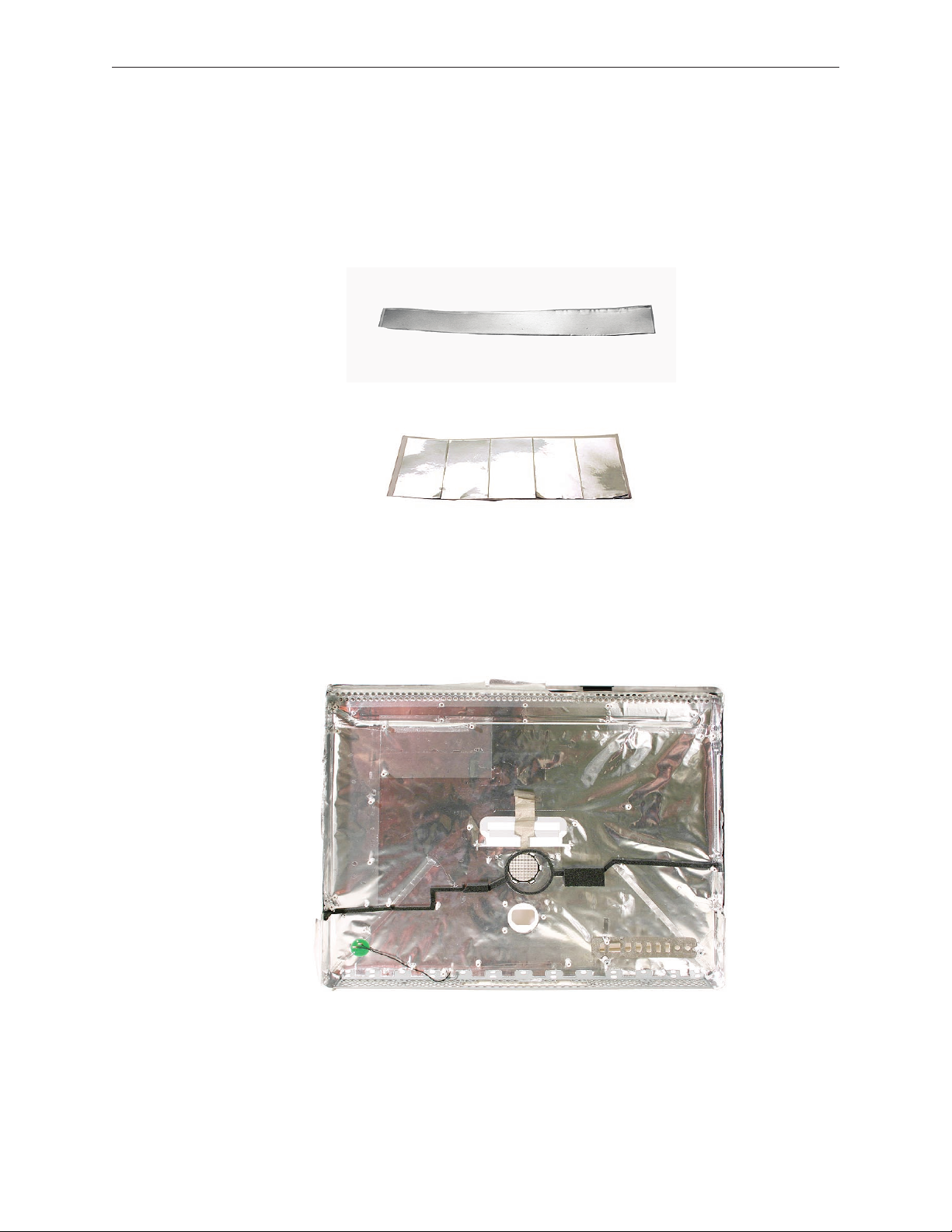
EMI Shielding
The iMac enclosure is wrapped in EMI shielding that is easily torn and damaged. To maintain
a properly shielded unit, you must repair all accidental tears and cracks to the shielding by
covering them with EMI tape. Order EMI tape, part number 922-4786 (a long, thin strip) or 9225026 (short, wide strips).
Cover nicks with EMI tape. Pay particular attention to the EMI shielding inside the rear housing,
shown below. The EMI shield is easily damaged when replacing modules.
•
iMac (20-inch Late 2006) Take Apart — General Information 14
Page 15

Lower EMI Shield
EMI tape covers the top and sides of the display panel, and the lower EMI shield covers the logic
board along the bottom of the unit. The EMI tape and lower EMI shield are easily damaged when
removed, and removal is necessary in order to access most components within the unit.
Should the EMI tape that seals the display, or the EMI shield covering the bottom of the enclosure
(see photo below) accidentally tear, use the EMI tape (922-4786 or 922-5026) to repair and
completely seal the unit.
iMac (20-inch Late 2006) Take Apart — General Information 15
Page 16

When properly repaired, all edges shown below will be wrapped by EMI tape, and the tape
securely adhered to all edges. Use a “black stick” to atten the EMI tape tightly and rub out air
pockets and wrinkles.
iMac (20-inch Late 2006) Take Apart — General Information 16
Page 17

What’s New
13 December 2007
Troubleshooting---> No Video--> Symptom 2: No Video, Boot Chime Heard, White LED ON: Step 4
was corrected to reference Step 7 instead of Step 8, which does not exist.
29 October 2007
A note was added to the Logic Board Replacement section to tell service providers to install the
iMac Firmware Update 1.2 (or later).
For proper performance and reliability of the Intel Core 2 Duo processors, apply the iMac •
rmware update after replacing the logic board. The rmware update allows Apple service
to consolidate the version 1 and version 2 logic boards.Refer to KBase article: Firmware
updates for Intel-based Macs.
The 661-4108 logic board will replaced by 661-4294•
The 661-4109 logic board will replaced by 661-4295•
The 661-4110 logic board will replaced by 661-4296•
The 661-4111 logic board will replaced by 661-4297•
16 October 2007
Corrected the Ambient Light Sensor part number on the Exploded View. diagram The correct •
part number is 922-7759.
23 April 2007
The • optical drive removal procedure has been updated. Using a screwdriver to release the
optical drive tabs is causing damage to the logic board. The updated procedure shows how
to remove the optical drive using a needlenose pliers.
Additional information on handling slot-load optical drives can be referenced in• Kbase
article 305282.
22 February 2007
Updated Upper Exploded View and created hyperlink to EEE code compatiblilty chart. •
16 February 2007
The AirPort Extreme Card and Logic Board sections in Take Apart have been updated with •
EEE code compatibility information. Before replacing either part, check for compatibility.
iMac (20-inch Late 2006) — What’s New 17
Page 18

12 January 2007
The “• No Power” symptom in Troubleshooting has been updated. If your computer won’t
turn on, try removing and reinstalling the SO-DIMMs.
4 December 2006
Troubleshooting has been updated with a new symptom, “• Display does not remain in its
intended position when tilted.”
11 November 2006
A drawing of the clutch mechanism (922-7002) was added to the Exploded View drawing.•
31 October 2006
Troubleshooting has been updated with a new symptom, “• Fans running at full speed after
computer turns on.” Note: The customer may have entered a diagnostic mode that causes
the fans to run at full speed. This symptom is very easy to resolve at the customer level.
29 September 2006
The inverter procedure was updated; the DC cable connection to the inverter changed.•
Photos of the EMI tape (922-44786 and 922-5026), used to repair torn and damaged EMI •
shielding, have been added to the EMI Shielding section in the General Information chapter
6 September 2006
Product Introduction: iMac (20-inch Late 2006)•
Logic board: Intel Core 2 Duo processor running at 2.16 or 2.33 GHz•
AirPort Extreme and Bluetooth antennas: Two AirPort antennas, one Bluetooth antenna •
Inverter Board : New service part, 661-4112. It serves as the at panel backlight controller.•
Camera Board: New service module, 661-4113, is smaller than previous camera boards.•
Memory: Accepts up to a 2 GB SO-DIMM in each of the two memory slots, but the iMac •
will only support 3 GB total memory
Rear cover and front bezel: New part numbers (922-7769 and 922-7875) with slight •
revisions to each part
DC-DC Board: There is no DC/DC board. The functionality previously accomplished on •
the DC/DC board has been integrated into the logic board
iMac (20-inch Late 2006) — What’s New 18
Page 19

Access Door
Tools
Phillips #2 screwdriver•
ESD-safe workstation and mat•
Soft , clean towel or cloth•
Preliminary Steps
Before you begin, lay the computer down so the panel is face down and the bottom is facing
you.
Part Location
iMac (Early 2006 20-inch) Take Apart — Access Door 19
Page 20

Removing the Access Door
Raise the stand and use a Phillips #2 screwdriver, to loosen the two captive access door 1.
screws.
Warning: The ambient light sensor is located to the left. Don’t mistake the ambient light
sensor for a screw. Sticking a screw driver or other sharp object in the ambient light sensor
could damage the computer.
Remove the access door. 2.
Replacing the Access Door
Position the access door on the rear housing over the memory compartment. 1.
Lift the stand out of the way.2.
Use a Phillips #2 screwdriver to tighten the captive screws.3.
iMac (Early 2006 20-inch) Take Apart — Access Door 20
Page 21

Front Bezel
Tools
This procedure requires the following tools:
Torx T8 screwdriver•
Access card tool 922-7172•
Preliminary Steps
Before you begin, remove the access door.
Part Location
iMac (20-inch Late 2006) Take Apart — Front Bezel 21
Page 22

922-7011 (x3)
922-7749 (x1)
Removing the Front Bezel
Position unit on rear cover with the stand facing you.1.
2. Tilt up the front bezel and remove four screws along the bottom. The longer screw is the
second screw from the right. It’s to the left of the ambient light sensor.
Warning: The ambient light sensor is located in the second hole from the right. Don’t
mistake the ambient light sensor for a screw. Sticking a screwdriver or other sharp object in
the ambient light sensor could damage the computer.
Locate the access card. Bending the upper quarter of the access tool card will help engage 3.
the latch. Note: Refer to AccessToolModication in the General Information chapter if the
bezel is dicult to open.
iMac (20-inch Late 2006) Take Apart — Front Bezel 22
Page 23

This picture shows how the access tool works. Pushing the tool up the vent on the rear cover 4.
releases the latches on the inside of the front bezel. Refer to the next step for the procedure.
Start on the left side (looking from the back of the unit). As you insert the card to disengage 5.
the latch, squeeze the top of the bezel, that will help take pressure o of the latch and
enable it to open easier. As the bezel releases, pull the bezel away from the rear housing.
Note: If the bezel won’t open, try cutting the card lengthwise into 3/4 inch or 1.5 cm strips.
Insert the card on a 45º angle, aimed toward the outer corner, and try again.
iMac (20-inch Late 2006) Take Apart — Front Bezel 23
Page 24

Repeat step 5 to release the locking latch in the right corner. Again, pull the bezel away as 6.
the card releases the latch.
If the bezel won’t release, pull the bottom of the bezel out a bit and insert the access card 7.
again.
iMac (20-inch Late 2006) Take Apart — Front Bezel 24
Page 25

Repeat step 7 for the left side. 8.
Once the access card has been removed, it is safe to open the bezel. Position the unit on an 9.
ESD mat, with the bottom facing toward you. Lift up the top of the bezel and pull it up and
slightly toward you. Caution: Make sure the memory eject levers are not protruding from the
access door when you lift the bezel up.
iMac (20-inch Late 2006) Take Apart — Front Bezel 25
Page 26

Swing the bezel up so you can disconnect two cables on the camera board at the top of the 10.
bezel.
Remove the any kapton tape and disconnect the camera and microphone cables from the 11 .
camera board.
Lift the front bezel o the computer. If replacing a damaged front bezel, also remove the 12.
camera board. Note the microphone is part of the front bezel assembly.
iMac (20-inch Late 2006) Take Apart — Front Bezel 26
Page 27

Replacing the Front Bezel
Make sure the black EMI shielding along the top of the LCD panel is not in the way of the 1.
locking mechanisms when you lower the front bezel onto the computer. Use a black stick to
press (re-stick) the EMI shielding along the top of the panel.
Connect the camera and microphone cables (on the camera board) to the cables sticking 2.
out of the top of the computer.
iMac (20-inch Late 2006) Take Apart — Front Bezel 27
Page 28

Tuck the cables neatly into the channel on the rear housing. 3.
Press the memory ejector levers into the closed position.4.
Continue to lower the font bezel down and press the top corners of the front bezel to 5.
connect the latches. Note: Check that the latches are connected by lifting the front bezel at
each corner.
Replace the four bezel mounting screws along the bottom of the computer.6.
Replace the access door; tighten the two captive screws.7.
iMac (20-inch Late 2006) Take Apart — Front Bezel 28
Page 29

Camera Board
Tools
Black stick •
ESD mat, soft , clean towel or cloth•
Preliminary Steps
Before you begin, remove the access door and front bezel.
Part Location
iMac (20-inch Late 2006) Take Apart — Camera Board 29
Page 30

Removing the Camera Board
The camera board and cables are visible as you lift the front bezel o the computer.1.
Remove any kapton tape on the cables. Disconnect the camera and microphone cables. 2.
Remove any kapton tape covering the camera board. With your ngernail or a black stick, 3.
gently lift/ip up the ex cable locking hinge to release the exible camera cable.
iMac (20-inch Late 2006) Take Apart — Camera Board 30
Page 31

With your ngers or black stick, ex the two black tabs forward to release the camera board 4.
from the camera bracket.
Remove the camera board from the front bezel. 5. Note: The ex cable, camera lens, and black
mounting bracket are part of the front bezel.
iMac (20-inch Late 2006) Take Apart — Camera Board 31
Page 32

Replacing the Camera Board
Position the camera board in the plastic bracket. Make sure the ex cable is not pinched as 1.
you install the board.
Snap the board into the mounting bracket and lock the ex cable into the connector with 2.
the locking hinge.
iMac (20-inch Late 2006) Take Apart — Camera Board 32
Page 33

Reapply the tape across the length of the camera board. 3.
Connect the two cables to the camera board. 4.
Tuck the camera board cables neatly into the channel on the rear housing. 5.
iMac (20-inch Late 2006) Take Apart — Camera Board 33
Page 34

Holding the memory ejector levers closed, lower the font bezel down.6.
Replace the bezel screws along the bottom of the computer.7.
Replace the access door; tighten the two captive screws.8.
iMac (20-inch Late 2006) Take Apart — Camera Board 34
Page 35

Lower EMI Shield
Tools
Black stick (or other nonconductive nylon or plastic at-blade tool).•
Preliminary Steps
Before you begin, remove the following:
A• ccess door
F• ront bezel
Part Location
iMac (20-inch Late 2006) Take Apart — Lower EMI Shield 35
Page 36

Removing the Lower EMI Shield
Carefully peel the lower EMI shield o the bottom edge of the rear housing. Use a black 1.
stick to help peel back the shield.
Gently lift the EMI shield to rest of the way to expose the other modules. 2.
iMac (20-inch Late 2006) Take Apart — Lower EMI Shield 36
Page 37

Replacing the Lower EMI Shield
Position the lower EMI shield over the bottom of the unit so that the holes (for the IR board 1.
and the LED) in the shield are properly aligned.
Press the sticky, edge of the EMI shield onto the bottom side of the display panel. The crease 2.
in the EMI shield should align with the edge of the panel.
Fold down the EMI shield and press it rmly over the bottom edge of the rear housing. Use a 3.
black stick to rub out any air bubbles and ensure that the EMI shield adheres rmly and
without wrinkles along all edges.
Make sure the memory eject levers are in the closed position before you replace the front 4.
bezel.
Replace the access door.5.
iMac (20-inch Late 2006) Take Apart — Lower EMI Shield 37
Page 38

IR Board
Tools
Torx T6 screwdriver.•
Preliminary Steps
Before you begin, remove the following:
A• ccess door
F• ront bezel
Lower EMI shield•
Part Location
iMac (20-inch Late 2006) Take Apart — IR Board 38
Page 39

922-7010
Removing the IR Board
1. Disconnect the IR cable and remove the two T6 screws on the IR board. Lift the IR board from
its mounting bracket.
922-7010
If necessary, 2. use a Torx T6 screwdriver to remove the IR board mounting bracket.
iMac (20-inch Late 2006) Take Apart — IR Board 39
Page 40

Note3. : If you are replacing the IR /camera cable, you must remove the optical drive and
disconnect the cable from the logic board.
iMac (20-inch Late 2006) Take Apart — IR Board 40
Page 41

Replacing the IR Board
If removed, route the IR/camera cable under the IR bracket. 1.
Install the IR board on the mounting bracket. Replace the T6 screws and connect the IR cable 2.
to the IR board.
iMac (20-inch Late 2006) Take Apart — IR Board 41
Page 42

Replace the lower EMI shield.3.
Position the memory eject levers into the closed position.4.
Replace the front bezel.5.
Replace the access door.6.
iMac (20-inch Late 2006) Take Apart — IR Board 42
Page 43

Battery
Tools
The only tool required for this procedure is a black stick.
Preliminary Steps
Before you begin, follow steps for removing the following:
A• ccess door
F• ront bezel
Lower EMI shiel• d
Part Location
iMac (20-inch Late 2006) Take Apart — Battery 43
Page 44

Removing the Battery
With a black stick, pry the battery from the battery slot. 1.
Replacing the Battery
Slide the battery (with voltage information face up) into the battery holder. 1.
Replace the lower EMI shield.2.
Replace the front bezel.3.
Replace the access door.4.
iMac (20-inch Late 2006) Take Apart — Battery 44
Page 45

LCD Display Panel
Tools
Torx T6 screwdriver.•
Torx T10 screwdriver•
Black stick (or other nonconductive nylon or plastic at-blade tool)•
Preliminary Steps
Before you begin, remove the following:
A• ccess door
F• ront bezel
Lower EMI shield•
Part Location
iMac (20-inch Late 2006) Take Apart — Display Panel 45
Page 46

Removing the Display Panel
Using the access tool, a black stick, or your ngers, peel the black EMI tape o the right and 1.
left sides of the panel.
Using the access tool or black stick, peel back the black EMI tape stuck along the entire 2.
length of the top panel.
iMac (20-inch Late 2006) Take Apart — Display Panel 46
Page 47

922-7010
3. Using a Torx T6 screwdriver, remove the two LVDS connector screws. Pull the black tab on the
connector to disconnect the LVDS cable from the logic board.
922-7023
4. Using a Torx T10 screwdriver, remove the four panel mounting screws.
iMac (20-inch Late 2006) Take Apart — Display Panel 47
Page 48

Lift the panel up just enough to see the inverter cables on the left side. 5.
Disconnect the two panel-to-inverter cables above the left speaker. 6. Replacement Note: The
cable connectors are marked with dots to indicate “right-side-up.”
iMac (20-inch Late 2006) Take Apart — Display Panel 48
Page 49

Raise the panel up the rest of the way. Disconnect the two inverter-to-display cables at the 7.
top of the inverter. Replacement Note: The cable connectors are marked with dots to
indicate “right-side up.”
Carefully separate the display from the sticky EMI shielding along the top of the display8. .
iMac (20-inch Late 2006) Take Apart — Display Panel 49
Page 50

Note9. : If replacing the display panel, remove the lower EMI shield, the display panel mounting
brackets (on each side), and the LVDS cable from the back of the display panel before
returning the module to Apple.
iMac (20-inch Late 2006) Take Apart — Display Panel 50
Page 51

Replacing the Display Panel
Replace the LVDS cable on the rear of the display panel.1.
If removed, replace the metal panel mounting brackets to each side of the display.2.
Connect the four inverter-to-display cable connectors. Remember the connectors are keyed; 3.
dot-side-up.
Replace the display panel with four mounting screws.4.
Connect the LVDS cable connector to the logic board and secure it with two screws.5.
Fold the EMI tape rmly over the left, top, and right edges of the display panel. Use your 6.
ngers or the black stick to adhere the tape rmly and rub out wrinkles. Note: If the tape
was ripped or damaged, replace the damaged EMI tape with new EMI tape
Replace the lower EMI shield. Press the EMI shield along the bottom and sides of the 7.
computer frame.
Replace the front bezel.8.
Replace the access door.9.
iMac (20-inch Late 2006) Take Apart — Display Panel 51
Page 52

Memory
Tools
Phillips #2 screwdriver•
ESD mat, soft , clean towel or cloth•
Preliminary Steps
Before you begin, remove the access door.
Part Location
iMac (20-inch Late 2006) Take Apart — Memory 52
Page 53

Removing the Memory
After removing the access door, touch the metal frame around the memory compartment to 1.
discharge any static electricity from your body.
Important: Always discharge static before you touch any parts such as the memory board.
To avoid generating static electricity, do not walk around the room until you have nished
replacing the memory.
Pull the two levers in the memory compartment toward you. If a memory module is installed 2.
in the slot, pulling the levers will dislodge it. Note: The levers are used to remove memory
not to install memory. Always install memory my hand.
a
Set the memory module aside.3.
iMac (20-inch Late 2006) Take Apart — Memory 53
Page 54

Replacing the Memory
Make sure the DIMM levers are all the way open. 1.
With the computer face down, orient the DIMM with the notch on the left. 2.
With your ngers, press the DIMM fully into the slot until you hear a click. After inserting the 3.
memory, fold the DIMM levers closed. There will be a slight resistance and you will hear a
click when they fold into the closed position.
Replace the access door on the memory compartment.4.
Use a Phillips #2 screwdriver to tighten the captive screws on the access door.5.
iMac (20-inch Late 2006) Take Apart — Memory 54
Page 55

iMac (20-inch Late 2006) Take Apart — Memory 55
Page 56

Speakers
Tools
Torx T10 screwdriver•
Preliminary Steps
Before you begin, remove the following:
A• ccess door
F• ront bezel
Lower EMI shield•
Display Pane• l
IR board•
Part Location
iMac (20-inch Late 2006) Take Apart — Speakers 56
Page 57

922-7014 (Left)
922-7015 (Right)
Removing the Speakers
1. Using a T10 torx screwdriver, remove the screws from the left and right speakers.
Replacement Note: The longer of the two speaker mounting screws is used to secure the
left speaker; the shorter screw secures the right speaker.
922-7010
2. Remove the tow T6 screws on the IR mounting bracket so the speaker cable insulation is not
sliced on the metal bracket.
iMac (20-inch Late 2006) Take Apart — Speakers 57
Page 58

If necessary, disconnect the hard drive cable (to the left of the IR bracket) from the logic 3.
board to allow easier removal of the speaker cable.
Note the speaker cable routing. The speaker wire runs below the heatsink and above the 4.
memory slot. Disconnect the speaker cable from the right side of the logic board.
Lift the speakers up and out of the computer. See the next photo for disconnecting the 5.
speaker.
iMac (20-inch Late 2006) Take Apart — Speakers 58
Page 59

Replacing the Speakers
Connect the speaker cable to the logic board. 1.
Install the speakers and route the speaker below the heatsink and above the memory slot.2.
Replace the IR mounting bracket making sure the speaker cable runs under the bracket. 3.
Replace the IR board.4.
Secure the right speaker with the smaller of the two mounting screws.5.
Secure the left speaker with the longer of the two mounting screws. 6.
Replace the display panel.7.
Replace the lower EMI shield.8.
Replace the front bezel.9.
Replace the access door.10.
iMac (20-inch Late 2006) Take Apart — Speakers 59
Page 60

AirPort Extreme Card
Tools
Torx T6 screwdriver•
Preliminary Steps
Before you begin, remove the following:
A• ccess door
F• ront bezel
Lower EMI shiel• d
Part Location
iMac (20-inch Late 2006) Take Apart — AirPort Extreme Card 60
Page 61

922-7010
Removing the AirPort Extreme Card
1. Disconnect the two AirPort antennas and remove the two T6 screws.
The board pops up when the screws are removed. Pull the AirPort Extreme card out of the 2.
slot in the direction of the arrow.
iMac (20-inch Late 2006) Take Apart — AirPort Extreme Card 61
Page 62

Replacing the AirPort Extreme Card
See the following section on compatibility to order the replacement part by EEE code.1.
Align the AirPort Extreme card with the slot on the logic board. Insert the board into the slot.2.
Replace the two T6 AirPort Extreme card screws.3.
Connect the antenna cables to the AirPort Extreme card.4.
Replace the lower EMI shield.5.
Replace the front bezel.6.
Replace the access door.7.
Checking Compatibility between AirPort Card and Logic Board
The iMac (Late 2006) computers were built with a number of logic boards and AirPort Extreme
cards. To avoid confusion identifying the correct logic board and AirPort Extreme card for the
system, refer to the table in this section which lists the corresponding EEE codes.
Locating the EEE Code
To locate the EEE code on the AirPort Extreme card, remove the card from the logic board. Turn
the card over, and look for the representative EEE code within the card’s serial number. Locate the
last four digits in the serial number. Drop the last digit (in this case, the letter “A”). The EEE code is
the next three digits. In this case it’s “VZL”, shown below.
iMac (20-inch Late 2006) Take Apart — AirPort Extreme Card 62
Page 63

To locate the EEE code on the logic board, locate the memory slot inside the computer. Locate
the last four digits in the serial number. Drop the last digit, in this case, the letter “A.” The EEE code
is the next three digits. In this case the EEE code is “WZH.”
EEE Code Table
Use the table below to identify the logic board and AirPort Extreme card EEE codes for the iMac
system. Order the correct service part based upon the corresponding EEE code. The table is
available in Knowledge Base article 305112-iMac(Late2006):AirPortCardDierences.
iMac Model Logic Board
Part #
iMac (20-inch Late
2006)
iMac (20-inch Late
2006)
661-4108,
Board , Logic,
2.16 GHz, 128
661-4109,
Board , Logic,
2.33 GHz, 128
Logic Board
EEE Code
VRG
VVA
WZF
WZH
W51
W53
WZK
WZM
AirPort
Extreme Card
Part #
661-4060,
B661-4060,
J661-4060,
KH661-4060,
PA661-4060,
Z661-4060
661-4060,
B661-4060,
J661-4060,
KH661-4060,
PA661-4060,
Z661-4060
AirPort
Extreme Card
EEE Code
VZL
VZM
VZN
VZR
VZP
VZQ
VZL
VZM
VZN
VZR
VZP
VZQ
iMac (20-inch Late 2006) Take Apart — AirPort Extreme Card 63
Page 64

iMac Model Logic Board
Part #
Logic Board
EEE Code
AirPort
Extreme Card
Part #
AirPort
Extreme Card
EEE Code
iMac (20-inch Late
2006)
iMac (20-inch Late
2006)
iMac (20-inch Late
2006)
iMac (20-inch Late
2006)
iMac (20-inch Late
2006
iMac (20-inch Late
2006
661-4110,
Board , Logic,
2.16 GHz, 256
661-4111,
Board , Logic,
2.33 GHz, 256
661-4294,
Board , Logic,
2.16 GHz, 128
661-4295,
Board , Logic,
2.33 GHz, 128
661-4296,
Board , Logic,
2.16 GHz, 256
661-4297,
Board , Logic,
2.33 GHz, 256
VV9
VVB
WZG
WZJ
W52,
W54
WZL
WZN
XYD
XYE
XYH
XYJ
XYF
XYG
XZM
XZN
661-4060,
B661-4060,
J661-4060,
KH661-4060,
PA661-4060,
Z661-4060
661-4060,
B661-4060,
J661-4060,
KH661-4060,
PA661-4060,
Z661-4060
661-4289,
B661-4289,
J661-4289,
KH661-4289,
PA661-4289,
Z661-4289
661-4289,
B661-4289,
J661-4289,
KH661-4289,
PA661-4289,
Z661-4289
661-4289,
B661-4289,
J661-4289,
KH661-4289,
PA661-4289,
Z661-4289
661-4289,
B661-4289,
J661-4289,
KH661-4289,
PA661-4289,
Z661-4289
VZL
VZM
VZN
VZR
VZP
VZQ
VZL
VZM
VZN
VZR
VZP
VZQ
WQX
WQY
WQZ
WR2
WR0
WR1
WQX
WQY
WQZ
WR2
WR0
WR1
WQX
WQY
WQZ
WR2
WR0
WR1
WQX
WQY
WQZ
WR2
WR0
WR1
iMac (20-inch Late 2006) Take Apart — AirPort Extreme Card 64
Page 65

Bluetooth Card
Tools
Torx T6 screwdriver•
Preliminary Steps
Before you begin, remove the following:
A• ccess door
F• ront bezel
Lower EMI shiel• d
Speaker• s
Part Location
iMac (20-inch Late 2006) Take Apart — Bluetooth Board 65
Page 66

922-7010
Removing the Bluetooth Board
1. Using a T6 torx screwdriver, remove the two screws on the Bluetooth board and disconnect
the antenna from the card.
Lift the card o the logic board. 2.
iMac (20-inch Late 2006) Take Apart — Bluetooth Board 66
Page 67

Replacing the Bluetooth Board
Press the Bluetooth board onto the logic board connector. 1.
Connect the Bluetooth antenna to the Bluetooth board. 2. Note: Make sure the card and
antenna are securely connected before installing the speakers.
Replace the two T6 Bluetooth board screws.3.
Replace the speakers and speaker screws. 4.
Replace the lower EMI shield.5.
Replace the front bezel.6.
Replace the access door.7.
iMac (20-inch Late 2006) Take Apart — Bluetooth Board 67
Page 68

Optical Drive
Tools
Torx T10 screwdriver•
Torx T6 screwdriver•
Needlenose pliers (with teeth)•
Preliminary Steps
Before you begin, remove the following:
A• ccess door
F• ront bezel
Lower EMI shield•
Display Pane• l
Part Location
iMac (20-inch Late 2006) Take Apart — Optical Drive 68
Page 69

922-7817
Removing the Optical Drive
1. Remove the two T6 wafer head screws from the optical drive ex cable. Disconnect the
exible cable and the optical drive sensor cable from the logic board.
Caution: Never press down on or grasp the body of the optical drive. Pressing or squeezing
the body of the optical drive could damage the mechanism.
Note2. : Make sure to use a needlenose pliers with teeth to remove the optical drive. The pliers
must have a textured surface to properly grasp the optical drive release tabs.
iMac (20-inch Late 2006) Take Apart — Optical Drive 69
Page 70

Locate the black tabs at each side of the plastic optical drive mounting bracket. Starting at 3.
the release tab that is furthest from the logic board, grasp the tab with needlenose pliers,
and ex the tab toward the optical drive exible cable. Use one nger underneath the edge
of the optical drive to gently lift up that corner of the drive.
Warning: iMac main logic boards returned with physical damage such as scratches, fractures,
or broken or missing components caused by improper servicing may be classied as
customer abuse. When using a tool to release the latches, be careful not to apply pressure to
the logic board or it may be damaged.
iMac (20-inch Late 2006) Take Apart — Optical Drive 70
Page 71

While avoiding the logic board, grasp the tab with needlenose pliers, and ex the tab toward 4.
the optical drive. Use one nger underneath the rear edge of the optical drive to gently tilt
up the end of the drive and remove the optical drive out of the housing.
iMac (20-inch Late 2006) Take Apart — Optical Drive 71
Page 72

This photo shows the optical drive out of the computer so you can visualize how the clips 5.
move. Pressing down (#1) releases the clips (#2) outward from the metal chassis.
Caution: Never press down on or grasp the body of the optical drive when removing or
installing it. Pressing or squeezing the body of the optical drive could damage the
mechanism.
6. If replacing the optical drive, use a T6 torx screwdriver to remove two ex cable screws
attaching to the optical drive. Note: Disconnect the ex cable and transfer it to the
replacement drive. Go on to the next step.
922-7817
iMac (20-inch Late 2006) Take Apart — Optical Drive 72
Page 73

If replacing the optical drive, disconnect the sensor cable from the optical sensor located on 7.
the underside of the optical drive. Transfer the sensor cable to the replacement drive.
iMac (20-inch Late 2006) Take Apart — Optical Drive 73
Page 74

922-7817
Replacing the Optical Drive
1. Install the ex cable to the optical drive with two T6 screws.
Insert the optical drive bezel into the rear housing, lining up the bezel with the slot opening 2.
(#1) . Be sure to align the two guide holes in the front bezel with guide posts at each end of
the drive access hole.
Push down on the mounting brackets (#2) to lock the optical drive securely into place on the
chassis.
Caution: Never press down on or grasp the body of the optical drive when installing it.
Pressing or squeezing the body of the optical drive could damage the mechanism.
iMac (20-inch Late 2006) Take Apart — Optical Drive 74
Page 75

Connect the optical sensor cable to the logic board. Route the sensor cable under the optical 3.
ex cable. Connect the ex cable to the logic board and replace the T6 screws.
Replace the display panel.4.
Replace the lower EMI shield.5.
Replace the front bezel.6.
Replace the access door.7.
iMac (20-inch Late 2006) Take Apart — Optical Drive 75
Page 76

Hard Drive
Tools
Torx T10 screwdriver•
Preliminary Steps
Before you begin, remove the following:
A• ccess door
F• ront bezel
Lower EMI shield•
Display Pane• l
Part Location
iMac (20-inch Late 2006) Take Apart — Hard Drive 76
Page 77

922-6800
Removing the Hard Drive
1. Remove the two T10 screws attaching the hard drive to the DC/DC inverter board
Disconnect the hard drive sensor cable from the connector on the logic board. Note 2. the
location of the sensor on the side of the hard drive and the routing of the sensor cable
under the heat pipes.
iMac (20-inch Late 2006) Take Apart — Hard Drive 77
Page 78

Holding the drive by the metal bracket, pull the hard drive toward the inverter and then up 3.
to release the hard drive mounting pins from the grommets on the chassis.
Disconnect the hard drive power and data cables from the end of the hard drive. 4.
iMac (20-inch Late 2006) Take Apart — Hard Drive 78
Page 79

922-7001
5. If you are replacing the hard drive, transfer the temperature sensor, mounting pins, and the
metal mounting bracket to the replacement drive.
iMac (20-inch Late 2006) Take Apart — Hard Drive 79
Page 80

Replacing the Hard Drive
Attach the hard drive sensor and sensor cable to the side of the hard drive. 1.
Attach the mounting bracket and pins if they were removed. Connect the hard drive data 2.
and power cables.
iMac (20-inch Late 2006) Take Apart — Hard Drive 80
Page 81

Route the hard drive sensor cable under the metal chassis. Connect the sensor cable to the 3.
logic board.
Insert the hard drive pins into the grommets. Lower the drive into the rear housing. 4.
iMac (20-inch Late 2006) Take Apart — Hard Drive 81
Page 82

Secure the two T10 screws on the hard drive mounting bracket to the inverter board. 5.
Replace the display panel.6.
Replace the lower EMI shield.7.
Replace the front bezel.8.
Replace the access door.9.
iMac (20-inch Late 2006) Take Apart — Hard Drive 82
Page 83

Power Supply
Tools
Torx T10 screwdriver•
Preliminary Steps
Before you begin, remove the following:
A• ccess door
F• ront bezel
Lower EMI shield•
Display Pane• l
Hard driv• e
Logic boar• d
Part Location
iMac (20-inch Late 2006) Take Apart —Power Supply, AC/DC 83
Page 84

Removing the AC/DC Power Supply
WARNING: The AC/DC power supply PCB remains powered up whenever the system is
plugged in, whether or not the system has been turned on. Use extreme caution when
troubleshooting the system with the front bezel removed.
Don’t work alone. In the event of an electrical shock it is important to have another •
individual present who can provide assistance.
Keep one hand in your pocket when working on any iMac (20-inch Late 2006) system •
that is plugged in. This will help ensure that your body does not provide a path to
ground in the event that you accidentally make contact with the line voltage.
Don’t wear jewelry, watches, necklaces, or other metallic articles that could present a •
risk if they accidentally make contact with the power supply circuitry.
1. Using a torx screwdriver, remove three self-tapping screws and one machine screw (bottom
right corner) on the power supply board. The top left screw also connects a ground cable to
the chassis; leave it attached to the chassis. Replacement Note: Install the machine screw
rst when installing the power supply.
922-7159 (x3)
922-6842
iMac (20-inch Late 2006) Take Apart —Power Supply, AC/DC 84
Page 85

Disconnect the two cables; the inverter cable on the left and the AC-DC power supply to AC 2.
power inlet cable on the right. The AC cable is tucked under the metal chassis. With your
ngers or a black stick, pry the cable free from the chassis and disconnect it. Lift the power
supply out of the chassis.
iMac (20-inch Late 2006) Take Apart —Power Supply, AC/DC 85
Page 86

Replacing the AC/DC Power Supply
WARNING: The AC/DC power supply PCB remains powered up whenever the system is
plugged in, whether or not the system has been turned on. Use extreme caution when
troubleshooting the system with the front bezel removed.
• Don’t work alone. In the event of an electrical shock it is important to have another
individual present who can provide assistance.
Keep one hand in your pocket when working on any iMac system that is plugged in. •
This will help ensure that your body does not provide a path to ground in the event
that you accidentally make contact with the line voltage.
Don’t wear jewelry, watches, necklaces, or other metallic articles that could present a •
risk if they accidentally make contact with the power supply circuitry.
iMac (20-inch Late 2006) Take Apart —Power Supply, AC/DC 86
Page 87

Connect the AC-DC power supply cable to the inverter on the left. Reconnect the power 1.
supply to AC power inlet cable. Tuck the AC power inlet cable under the metal chassis.
Replace the four power supply screws. Install the machine screw (bottom right corner) rst 2.
when installing the power supply.
Replace the hard drive.3.
iMac (20-inch Late 2006) Take Apart —Power Supply, AC/DC 87
Page 88

Replace the logic board.4.
Replace the display panel.5.
Replace the lower EMI shield.6.
Replace the front bezel.7.
Replace the access door.8.
Replace the display panel.9.
Replace the lower EMI shield.10.
Replace the front bezel.11.
Replace the access door.12.
iMac (20-inch Late 2006) Take Apart —Power Supply, AC/DC 88
Page 89

Logic Board
Tools
Torx T10 screwdriver•
Torx T6 screwdriver•
Preliminary Steps
Before you begin, remove the following:
A• ccess door
F• ront bezel
Lower EMI shield•
Display Pane• l
Optical Driv• e
Disconn• ect the IR board
Disco• nnect the AirPort antennas
Disconnect the Bluetooth antenn• a
Part Location
iMac (20-inch Late 2006) Take Apart —Logic Board 89
Page 90

Removing the Logic Board
Disconnect the eight cables from the connectors on the logic board. 1.
922-???? (extra
long screw)
922-6800
922-6842
2. Remove seven T10 screws. Screws are labeled below as self-tapping or machine screws.-
iMac (20-inch Late 2006) Take Apart —Logic Board 90
Page 91

922-7817
3. At the top of the heatsink, remove the two T6 screws that attach the logic board support
brackets (clips) to the chassis. Note: The L–shaped support brackets must be removed and
transferred to the heatsink on the replacement logic board.
Holding the board on each side, lift it up and toward the top of the computer. 4. Note: Remove
the memory module from the slot before returning the board to Apple
iMac (20-inch Late 2006) Take Apart —Logic Board 91
Page 92

Replacing the Logic Board
Replacement Note: iMac Firmware Update 1.2 (or later) Required
For proper performance and reliability of the Intel Core 2 Duo processors, apply the iMac
rmware update after replacing the logic board. Refer to KBase article: Firmware updates for
Intel-based Macs.
See the following section on 1. compatibility to order the replacement part by EEE code.
Position all the logic board cables out of the way so the logic board can be placed into the 2.
rear housing.
As you lower the board into the rear housing, make sure the memory levers are lowered 3.
through the access door opening and the logic board screw holes line up with the board.
At the top of the heatsink, re4. place the two T6 screws attaching the logic board support
bracket to the chassis. Note: The L–shaped support brackets must be transferred to the
replacement logic board.
iMac (20-inch Late 2006) Take Apart —Logic Board 92
Page 93

Make sure the hard drive sensor and the sensor cable are attached to the side of the hard 5.
drive. Route the sensor cable under the chassis and connect it to the logic board.
Connect the optical drive sensor cable, optical ex cable, optical clip, and replace the optical 6.
clip screws.
iMac (20-inch Late 2006) Take Apart —Logic Board 93
Page 94

Using a T10 torx screwdriver, replace the seven screws on the board. Always install the 7.
machine screws before installing the self-tapping screws.
iMac (20-inch Late 2006) Take Apart —Logic Board 94
Page 95

Connect the cables to the connectors on the logic board. 8.
Connect the AirPort and Bluetooth antennas.9.
Replace the speakers.10.
Replace the IR board and connect the IR cable.11.
Replace the display panel.12.
Replace the lower EMI shield.13 .
Replace the front bezel.14.
Replace the memory access door.15 .
Checking Compatibility between Logic Board and AirPort Card
The iMac (Late 2006) computers were built with a number of logic boards and AirPort Extreme
cards. To avoid confusion identifying the correct logic board and AirPort Extreme card for the
system, refer to the table in this section which lists the corresponding EEE codes.
Locating the EEE Code
To locate the EEE code on the AirPort Extreme card, remove the card from the logic board. Turn
the card over, and look for the representative EEE code within the card’s serial number. Locate the
last four digits in the serial number. Drop the last digit (in this case, the letter “A”). The EEE code is
the next three digits. In this case it’s “VZL”, shown below.
iMac (20-inch Late 2006) Take Apart —Logic Board 95
Page 96

To locate the EEE code on the logic board, locate the memory slot inside the computer. Locate
the last four digits in the serial number. Drop the last digit, in this case, the letter “A.” The EEE code
is the next three digits. In this case the EEE code is “WZH.”
iMac (20-inch Late 2006) Take Apart —Logic Board 96
Page 97

EEE Code Table
Use the table below to identify the logic board and AirPort Extreme card EEE codes for the iMac
system. Order the correct service part based upon the corresponding EEE code. The table is
available in Knowledge Base article 305112-iMac(Late2006):AirPortCardDierences.
iMac Model Logic Board
Part #
iMac (20-inch Late
2006)
iMac (20-inch Late
2006)
iMac (20-inch Late
2006)
iMac (20-inch Late
2006)
iMac (20-inch Late
2006)
661-4108,
Board , Logic,
2.16 GHz, 128
661-4109,
Board , Logic,
2.33 GHz, 128
661-4110,
Board , Logic,
2.16 GHz, 256
661-4111,
Board , Logic,
2.33 GHz, 256
661-4294,
Board , Logic,
2.16 GHz, 128
Logic Board
EEE Code
VRG
VVA
WZF
WZH
W51
W53
WZK
WZM
VV9
VVB
WZG
WZJ
W52
W54
WZL
WZN
XYD
XYE
AirPort
Extreme Card
Part #
661-4060,
B661-4060,
J661-4060,
KH661-4060,
PA661-4060,
Z661-4060
661-4060,
B661-4060,
J661-4060,
KH661-4060,
PA661-4060,
Z661-4060
661-4060,
B661-4060,
J661-4060,
KH661-4060,
PA661-4060,
Z661-4060
661-4060,
B661-4060,
J661-4060,
KH661-4060,
PA661-4060,
Z661-4060
661-4289,
B661-4289,
J661-4289,
KH661-4289,
PA661-4289,
Z661-4289
AirPort
Extreme Card
EEE Code
VZL
VZM
VZN
VZR
VZP
VZQ
VZL
VZM
VZN
VZR
VZP
VZQ
VZL
VZM
VZN
VZR
VZP
VZQ
VZL
VZM
VZN
VZR
VZP
VZQ
WQX
WQY
WQZ
WR2
WR0
WR1
iMac (20-inch Late 2006) Take Apart —Logic Board 97
Page 98

iMac Model Logic Board
Part #
Logic Board
EEE Code
AirPort
Extreme Card
Part #
AirPort
Extreme Card
EEE Code
iMac (20-inch Late
2006)
iMac (20-inch Late
2006
iMac (20-inch Late
2006
661-4295,
Board , Logic,
2.33 GHz, 128
661-4296,
Board , Logic,
2.16 GHz, 256
661-4297,
Board , Logic,
2.33 GHz, 256
XYH
XYJ
XYF
XYG
XZM
XZN
661-4289,
B661-4289,
J661-4289,
KH661-4289,
PA661-4289,
Z661-4289
661-4289,
B661-4289,
J661-4289,
KH661-4289,
PA661-4289,
Z661-4289
661-4289,
B661-4289,
J661-4289,
KH661-4289,
PA661-4289,
Z661-4289
WQX
WQY
WQZ
WR2
WR0
WR1
WQX
WQY
WQZ
WR2
WR0
WR1
WQX
WQY
WQZ
WR2
WR0
WR1
iMac (20-inch Late 2006) Take Apart —Logic Board 98
Page 99

AC Power Inlet
Tools
Torx T10 screwdriver•
Preliminary Steps
Before you begin, remove the following:
A• ccess door
F• ront bezel
Lower EMI shield•
Display Pane• l
Sp• eakers
Hard driv• e
Logic boar• d
CPU Fa• n
Part Location
iMac (20-inch Late 2006) Take Apart —AC Power Inlet 99
Page 100

922-6800
922-7069 (x1)
Removing the AC Line Filter
1. Using a torx T10 screwdriver, remove the three self-tapping screws from the power inlet and
the machine screw from the ground cable . Remove the EMI tape on the lter.
Disconnect the AC lter cable from the power supply. Notice the routing of the AC lter 2.
cable under the chassis.
Lift the AC lter out of the rear housing. 3.
iMac (20-inch Late 2006) Take Apart —AC Power Inlet 100
 Loading...