

Page 1
Service Source
iMac (17-inch Late 2006)
29 October 2007
© 2006 Apple Inc. All rights reserved.
Page 2

iMac (17-inch Late 2006)
Contents
Take Apart
General Information 6
Product View 6
Note About Images in This Manual 6
Tools Required 7
Serial Number Location 8
Safety 9
Opening the Computer 10
Access Tool Modication 11
EMI Shielding 13
What’s New 16
29 October 2007 16
23 April 2007 16
22 February 2007 16
16 February 2007 16
12 January 2007 16
11 November 2006 16
31 October 2006 17
29 September 2006 17
6 September 2006 17
Access Door 19
Memory 21
Front Bezel 24
Camera Board 33
Lower EMI Shield 37
IR Board 39
AirPort Extreme Card 42
Battery 47
LCD Display 50
ii
Page 3

LVDS Display Cable 57
Inverter 61
Speakers 64
Bluetooth Board 68
Optical Drive 70
Hard Drive 77
DC-DC Board 82
Power Supply 85
Logic Board 90
CPU Fan 99
Optical Drive Fan 101
Hard Drive Fan 104
AC Power Inlet 107
Ambient Light Sensor Board 111
Clutch Mechanism 114
AirPort Antennas 119
Bluetooth Antenna 123
Camera Cable 127
Chassis 131
Rear Housing 134
DC Power Cable 135
Troubleshooting
General Information 139
Serial Number 139
Block Diagram 139
Power On Self Test (POST) 14 0
Intel-based Mac computers such as the iMac (17-inch Late 2006) rely on a combination of
tones and blinking LEDs to display Power On Self Test (POST) error codes. 140
DDR Memory 141
iii
Page 4

How to Reset the System Management Controller (SMC) 142
Diagnostic LEDs 143
Symptom Charts 145
Power Issues 146
No Video 148
Display 151
Hard Drive 152
Optical Drive 154
Fan Sound 159
AirPort 162
Bluetooth 163
IR Remote 164
IR Sensor/Receiver 165
Built-in iSight Camera 166
Speakers 168
Mouse 169
Keyboard 170
Error Beep(s) 171
USB 172
Views
iMac (17-inch Late 2006)—Upper Exploded View 17 4
iMac (17-inch Late 2006)—Lower Exploded View 175
Screw Charts 176
Screw Charts 176
iv
Page 5

Service Source
Take Apart
iMac (17-inch Late 2006)
© 2006 Apple Computer, Inc. All rights reserved.
Page 6

Product View
General Information
Note About Images in This Manual
Because a pre-production model was used for most of the images shown in this manual, you may
notice small dierences in appearance between the image pictured and the computer you are
servicing. However, although the appearance diers, the steps and sequence are the same unless
noted.
iMac (17-inch Late 2006) Take Apart — General Information 6
Page 7

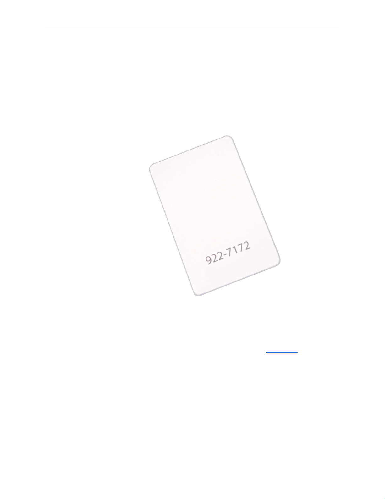
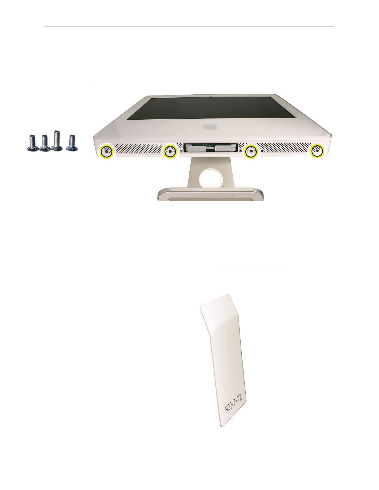
Tools Required
The following tools are required to service the computer. Note that a special access card (part
922-7172) is required to open the front bezel.
ESD-safe workstation and mat•
Soft, clean towel or cloth (to protect the display and removed parts from scratches)•
Access card (part 922-7172)•
Black stick (or other nonconductive nylon or plastic at-blade tool)•
Phillips #1 screwdriver•
Phillips #2 screwdriver•
Torx T8 screwdriver (magnetized)•
Torx T6 screwdriver (magnetized)•
Torx T10 screwdriver (magnetized)•
Flat-blade screwdriver•
iMac (17-inch Late 2006) Take Apart — General Information 7
Page 8
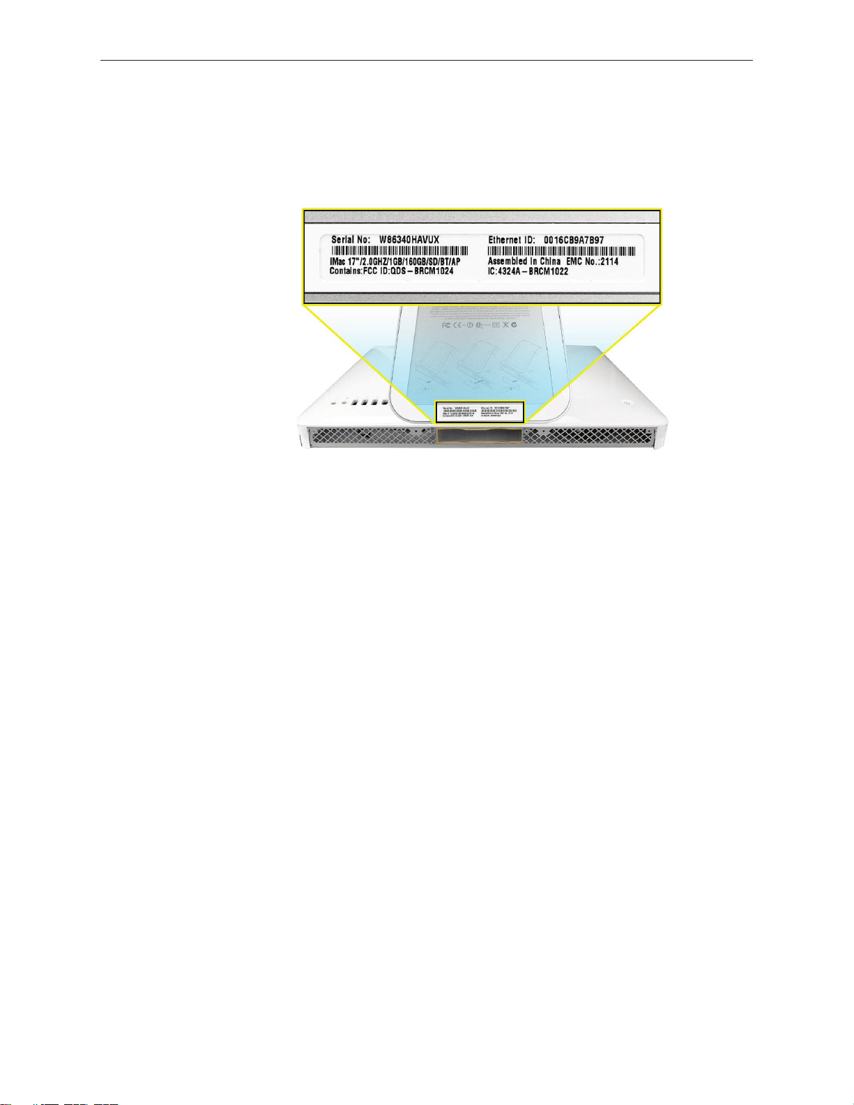
Serial Number Location
iMac serial numbers are located on the bottom of the computer stand.
iMac (17-inch Late 2006) Take Apart — General Information 8
Page 9
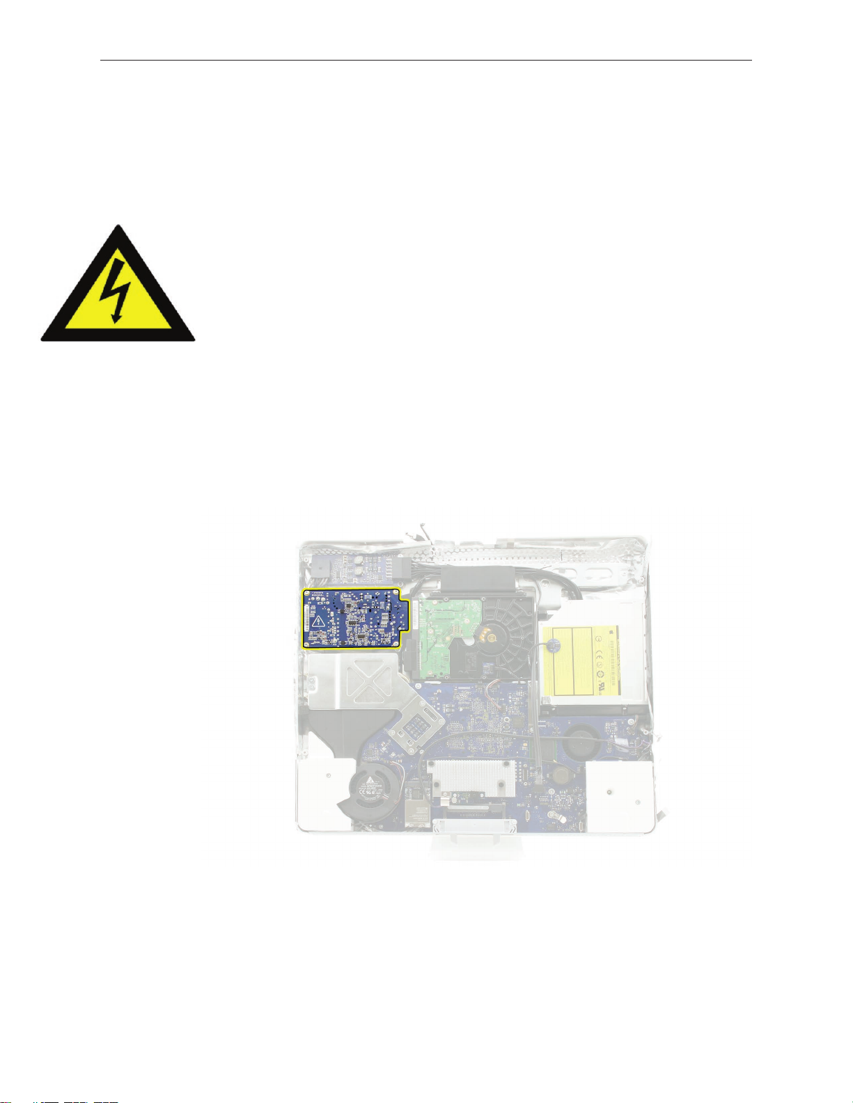
Safety
Warning: When the iMac is under power, be aware that the power supply contains high voltages
that pose a potential hazard to your personal safety. Never work on or near the power supply
with the unit powered on, and as a further precaution always make sure the unit is unplugged
when working on it with the front bezel removed.
WARNING: HIGH VOLTAGE
Text or photographs marked by this symbol indicate that a potential hazard to your personal
safety exists from a high voltage source.
The power supply board is a high voltage source with the unit under power, and remains
powered up whenever the system is plugged in, whether or not the system is turned on. Use
extreme caution when troubleshooting the system with the front bezel removed.
Disconnect power to the system before performing maintenance• .
Don’t work alone. In the even• t of an electrical shock it is important to have another
individual present who can provide assistance.
Keep one hand in your pocket when working on any iMac that is plugged in. This will •
help ensure that your body does not provide a path to ground in the event that you
accidentally make contact with the line voltage.
Don’t wear jewelry, watches, necklaces, or other metallic articles that could present a risk •
if they accidentally make contact with the power supply circuitry.
iMac (17-inch Late 2006) Take Apart — General Information 9
Page 10
Opening the Computer
Apple authorized, desktop certied technicians only should ever remove the front bezel on the
iMac. When the front bezel is removed, be sure to always ground yourself and follow ESD-safe
repair practices
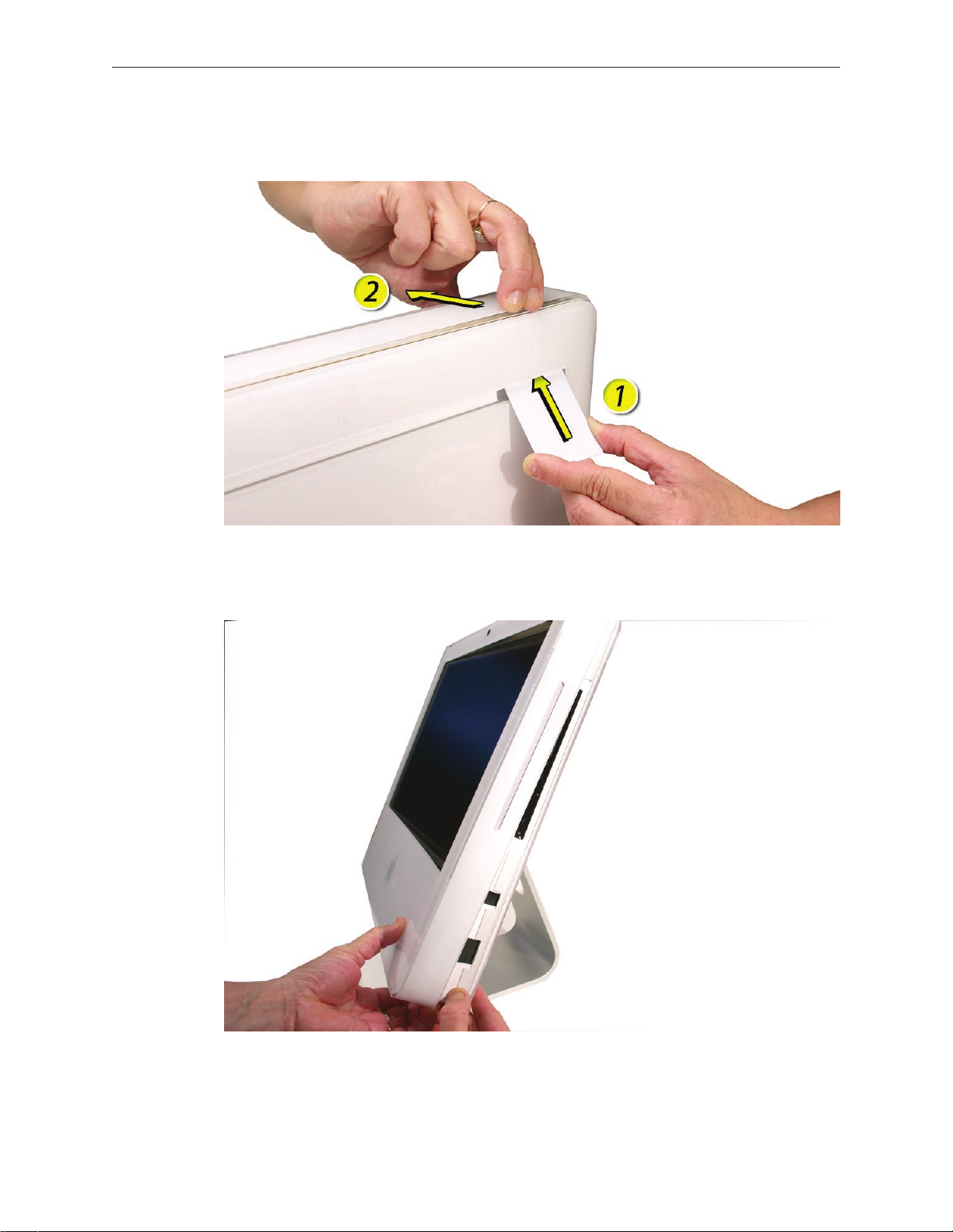
Removing the front bezel requires using a special access card (part 922-7172) to release latches
located inside the upper corners of the front bezel. Slightly bending the upper quarter of the
access tool card will help engage the latch more securely.
As you are inserting the card to disengage the latch squeeze the top of the bezel, that will help
take pressure o of the latch and enable it to open easier. Note: If the bezel won’t open, read the
next topic, Access Tool Modication.
Once the card has been released it is safe to open the bezel. See the Front Bezel Take Apart
procedure for more information.
iMac (17-inch Late 2006) Take Apart — General Information 10
Page 11
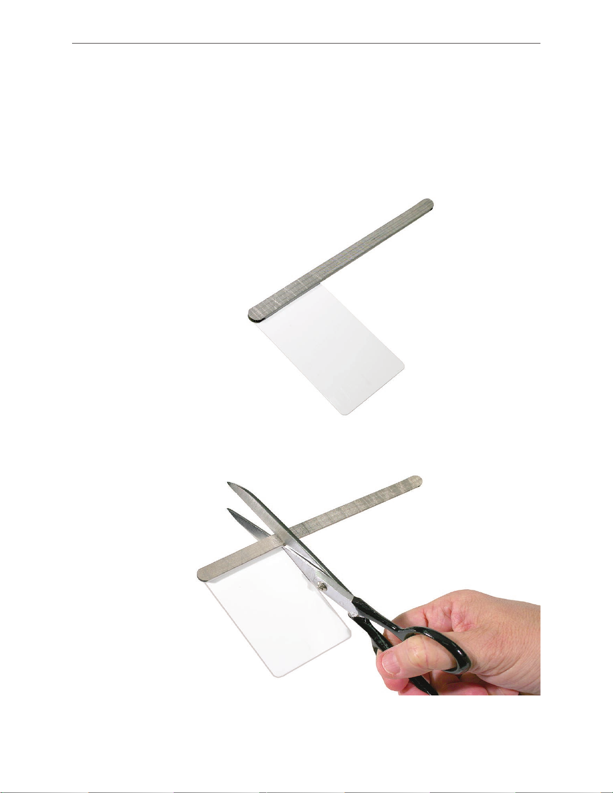
Access Tool Modication
If you wish to modify the access card tool, order kit 076-1213. The kit contains an access card and
a piece of EMI gasket that can be cut and added to the top of the card. The additional thickness
on the card will improve the contact with each bezel latch.
Remove the tape on the gasket to expose the sticky side of the gasket. Attach the sticky side 1.
of the EMI gasket to the top of the access card.
Cut the EMI gasket to the edge of the access card. 2.
iMac (17-inch Late 2006) Take Apart — General Information 11
Page 12
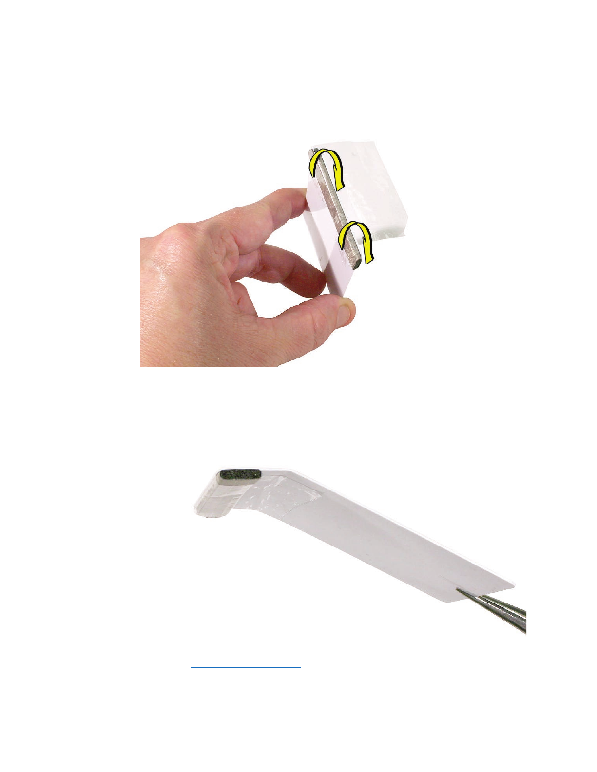
Using packing tape, or something equivalent, fold the tape over the EMI gasket to attach the 3.
gasket to the card.
Bend the card at a slight angle at the top to make sure the card makes contact with each 4.
latch.
Refer to 5. Removing the Front Bezel for the complete procedure.
iMac (17-inch Late 2006) Take Apart — General Information 12
Page 13
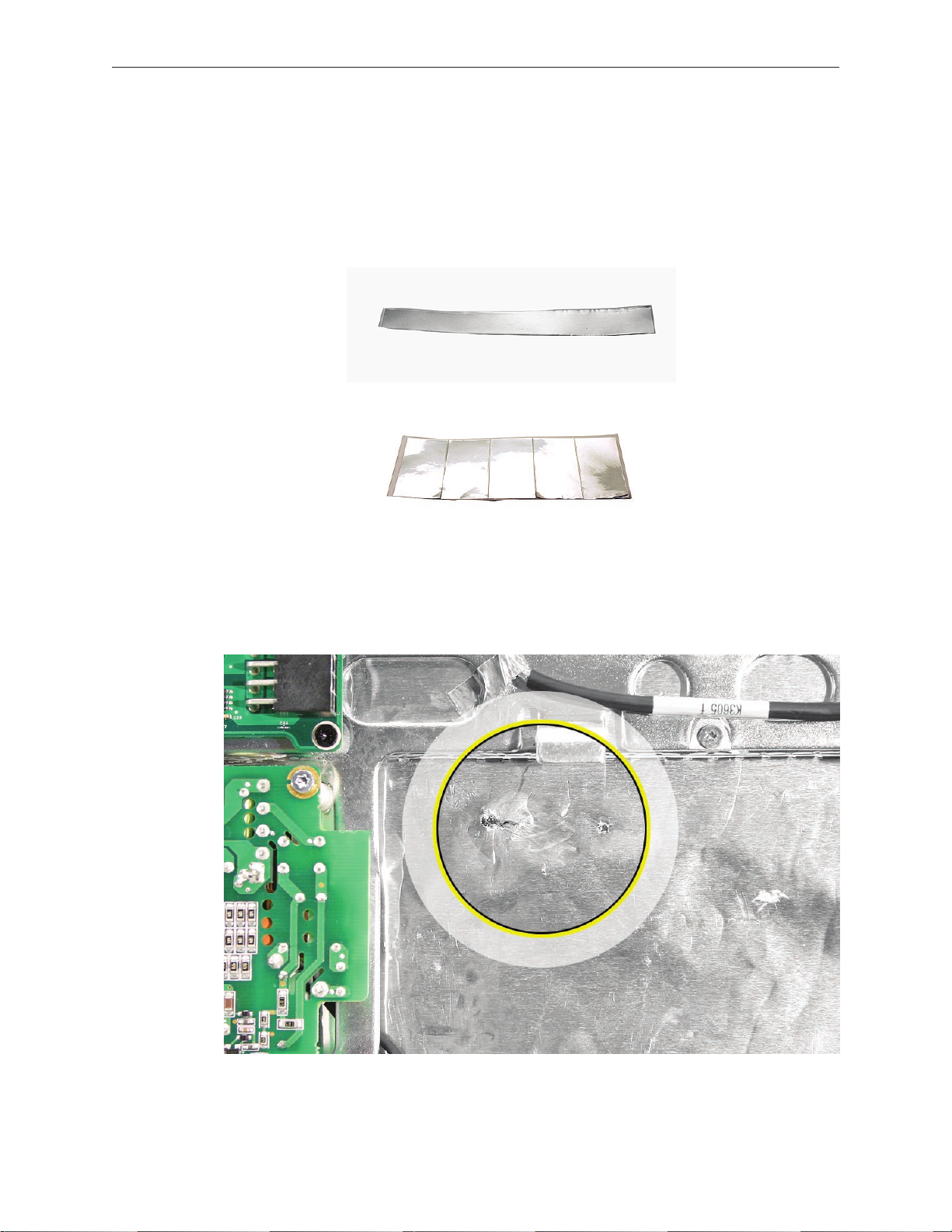
EMI Shielding
The iMac enclosure is wrapped in EMI shielding that is easily torn and damaged. To maintain a
properly shielded unit, you must repair all accidental tears and cracks to the shielding by
covering them with EMI tape. Order EMI tape, part number 922-4786 (a long, thin strip) or
922-5026 (short, wide strips).
Cover nicks, such as the those shown below, with EMI tape. Pay particular attention to the EMI
shielding inside the rear housing, shown below. The EMI shield is easily damaged when replacing
modules.
iMac (17-inch Late 2006) Take Apart — General Information 13
Page 14
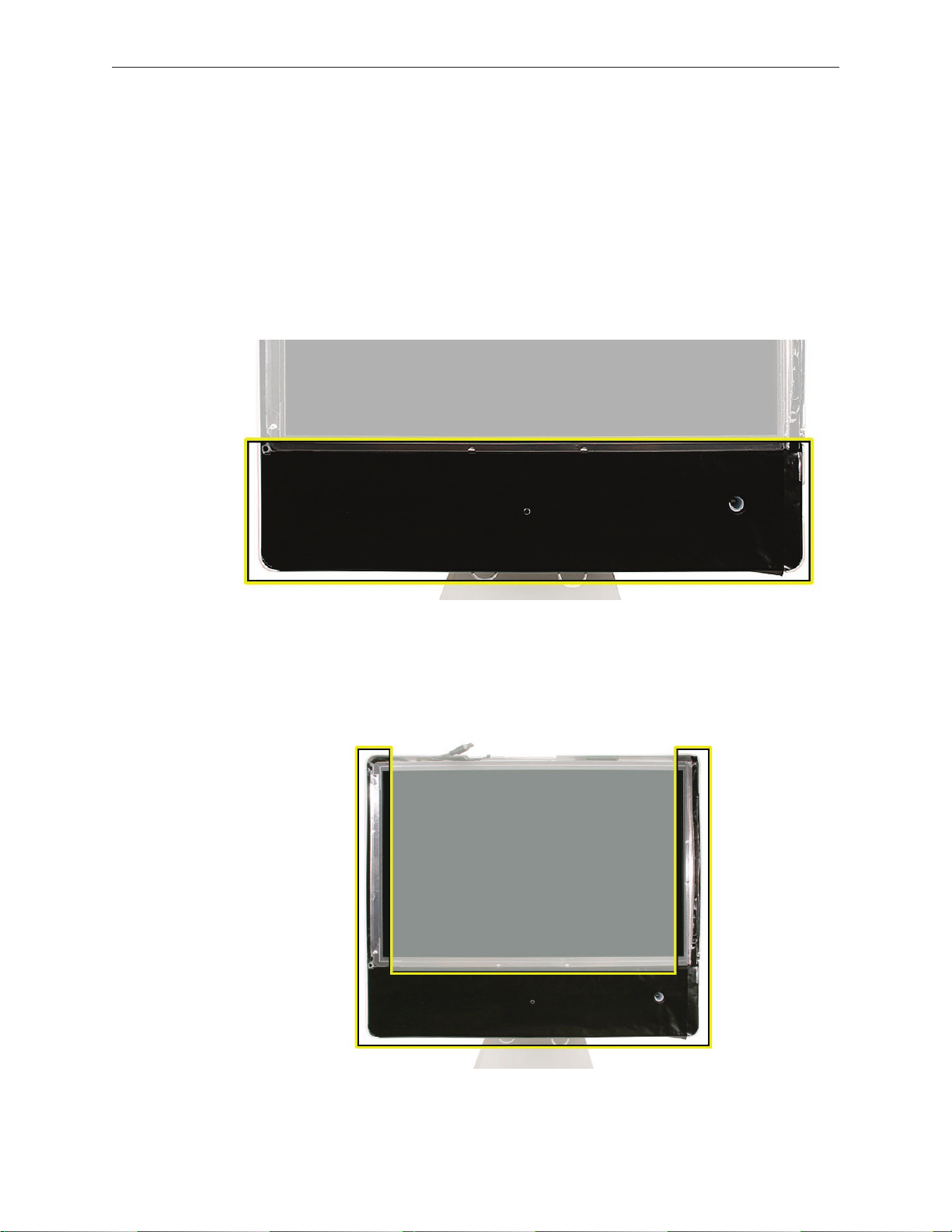
Lower EMI Shield
EMI tape covers the top and sides of the display panel, and the lower EMI shield covers the logic
board along the bottom of the unit. The EMI tape and lower EMI shield are easily damaged when
removed, and removal is necessary in order to access most components within the unit.
Should the EMI tape that seals the display, or the EMI shield covering the bottom of the
enclosure (see photo below) accidentally tear, use EMI tape (922-4786 or 922-5026) to repair and
completely seal the unit.
When properly repaired, all edges shown below will be wrapped by EMI tape, and the tape
securely adhered to all edges. Use a black stick to atten the EMI tape tightly and rub out air
pockets and wrinkles.
iMac (17-inch Late 2006) Take Apart — General Information 14
Page 15

iMac (17-inch Late 2006) Take Apart — General Information 15
Page 16

What’s New
29 October 2007
A note was added to the Logic Board Replacement section to inform service providers to install the
iMac Firmware Update 1.2 (or later)
For proper performance and reliability of the Intel Core 2 Duo processors, apply the iMac •
rmware update after replacing the logic board. The rmware update also allows Apple
service to consolidate the version 1 and version 2 logic boards. Refer to Kbase article:
Firmware updates for Intel-based Macs.
The 661-4105 logic board will be replaced by 661-4290•
The 661-4106 logic board will be replaced by 661-4291•
23 April 2007
The • optical drive removal procedure has been updated. Using a screwdriver to release the
optical drive tabs is causing damage to the logic board. The updated procedure shows how
to remove the optical drive using a needlenose pliers.
Additional information on handling slot-load optical drives can be referenced in• Kbase
article 305282.
22 February 2007
Updated Upper Exploded View and created hyperlink to EEE code compatiblilty chart. •
16 February 2007
The AirPort Extreme Card and Logic Board sections in Take Apart have been updated with •
EEE code compatibility information. Before replacing either part, check for compatibility.
12 January 2007
The “• No Power” symptom in Troubleshooting has been updated. If your computer won’t
turn on, try removing and reinstalling the SO-DIMMs.
11 November 2006
The clutch (922-7074) was renamed “clutch mechanism” in the Exploded View drawing.•
iMac (17-inch Late 2006) Take Apart — General Information 16
Page 17

31 October 2006
Troubleshooting has been updated with a new symptom, “• Fans running at full speed after
computer turns on.” Note: The customer may have entered a diagnostic mode that causes
the fans to run at full speed. This symptom is very easy to resolve at the customer level.
29 September 2006
Photos of the EMI tape (922-44786 and 922-5026), used to repair torn and damaged EMI •
shielding, have been added to the EMI Shielding section in the General Information chapter.
The logic board section has been updated with new photos for screw and cable locations. •
The inverter and display panel sections have an updated photo showing the clear tape •
locations on the back of the panel.
The display panel section has been updated to show the placement location of three pieces •
of EMI tape that attach from the bottom of the panel to the lower EMI shield.
6 September 2006
Product Introduction: iMac (17-inch Late 2006)
Logic board, 2GHz Intel Core 2 Duo processor•
Two built-in AirPort Extreme wireless antennas •
Built-in wireless Bluetooth 2.0 module standard •
1GB of 667MHz DDR2 SDRAM standard, PC2-5300, supports up to 3.0 GB system •
memory
160, 250, 500 GB hard drive with serial ATA•
Troubleshooting LED• s are located under the SATA drive cable and to the left of the
battery
iMac (17-inch Late 2006) Take Apart — General Information 17
Page 18

iMac (17-inch Late 2006) Take Apart — General Information 18
Page 19
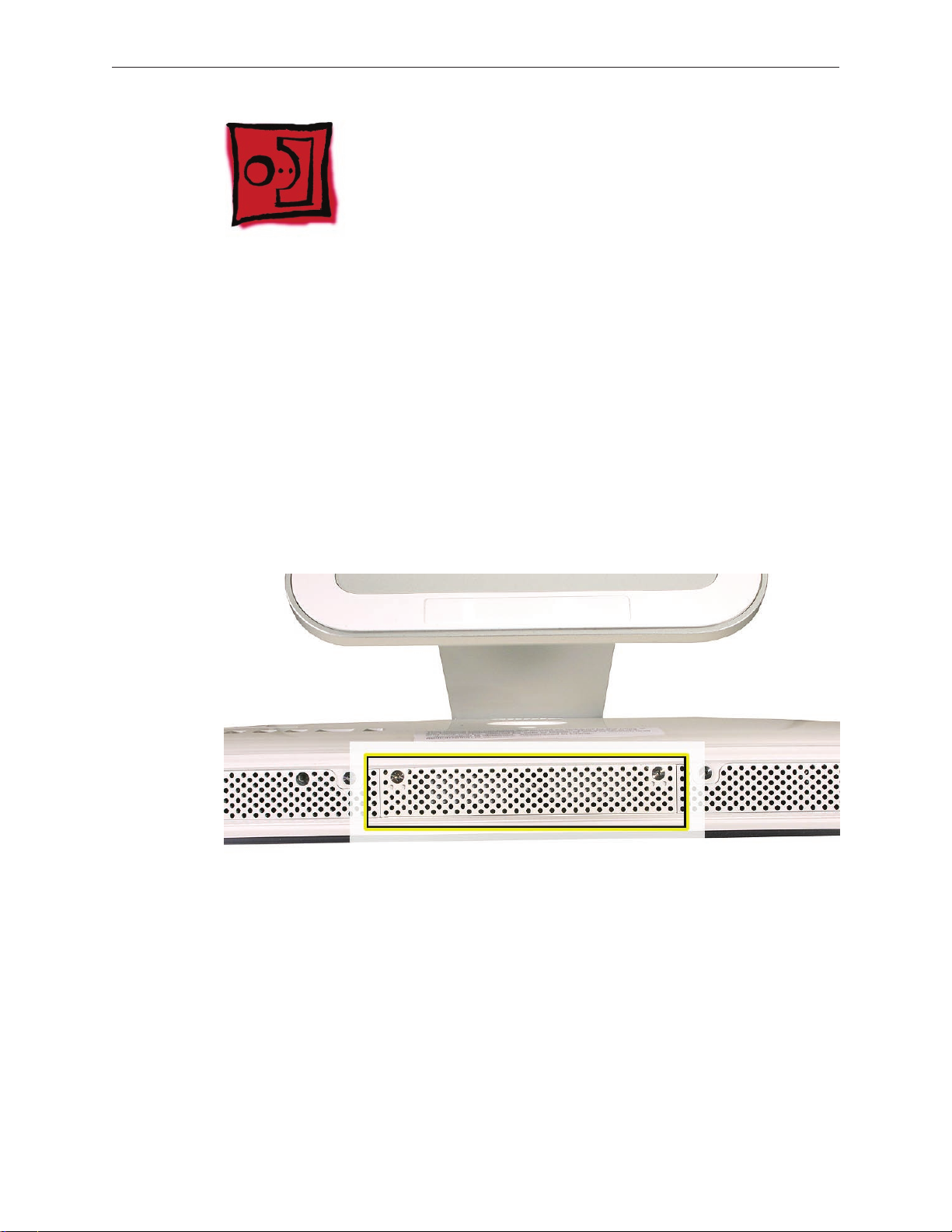
Access Door
Tools
Phillips #2 screwdriver•
ESD-safe workstation and mat •
Soft, clean towel or cloth•
Preliminary Steps
Before you begin, lay the computer down so the panel is face down and the bottom is facing
you.
Part Location
iMac (17-inch Late 2006) Take Apart — Access Door 19
Page 20
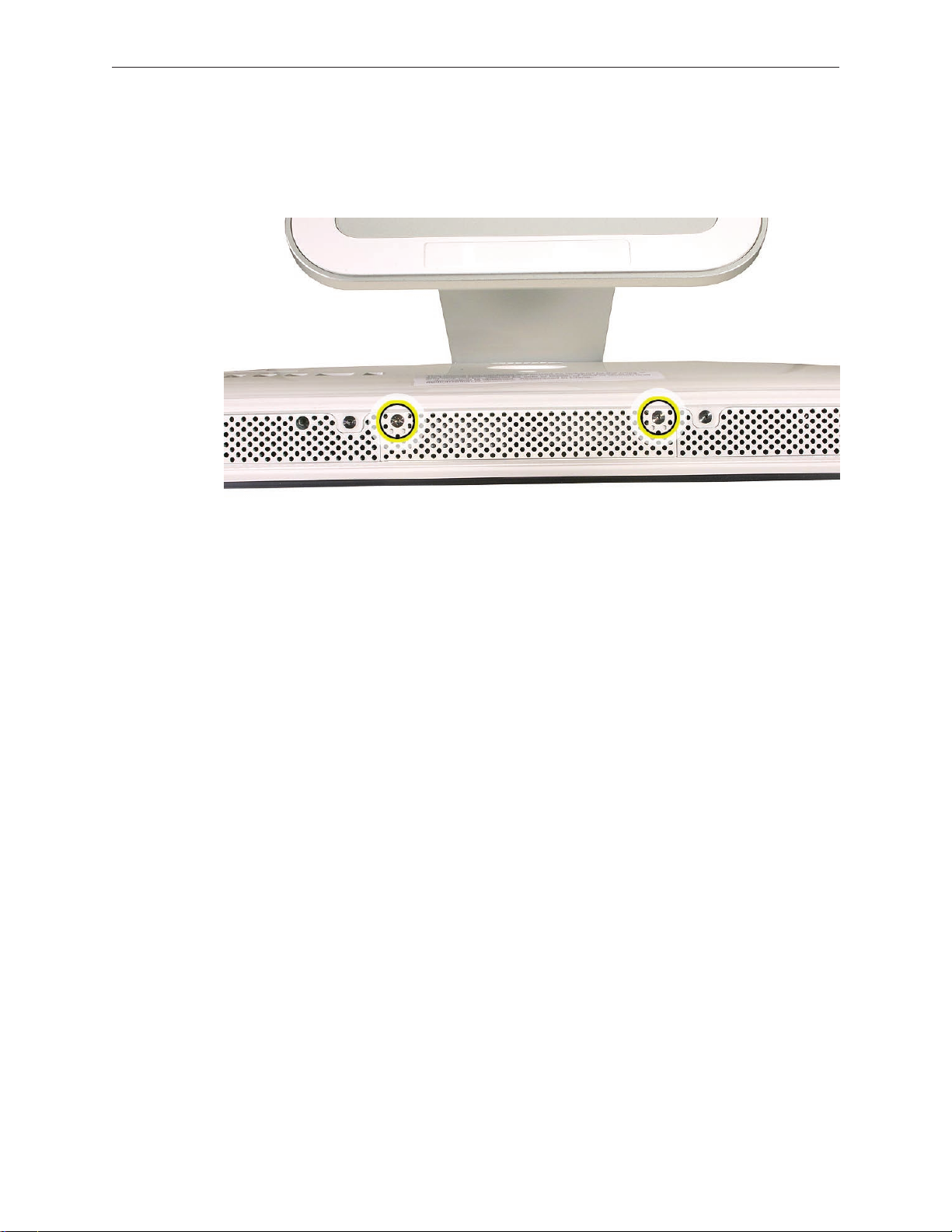
Removing the Access Door
Raise the stand and use a Phillips #2 screwdriver to loosen the two captive screws that 1.
secure the memory access door. Remove the access door.
Replacing the Access Door
Make sure the memory ejector tabs are in the closed position before attaching the access 1.
door.
Position the access door on the rear housing over the memory compartment. 2.
Lift the stand out of the way. 3.
Use a Phillips #2 screwdriver to tighten the captive screws. 4.
iMac (17-inch Late 2006) Take Apart — Access Door 20
Page 21
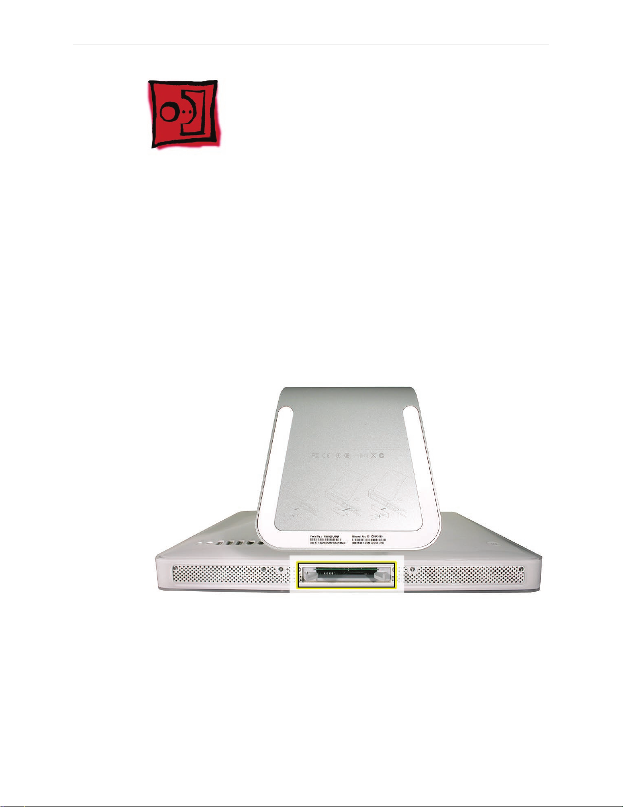
Memory
Tools
Phillips #2 screwdriver•
ESD-safe workstation and mat•
Soft, clean towel or cloth•
Preliminary Steps
Before you begin, lay the computer down so the panel is face down and the bottom is facing
you.
Part Location
iMac (17-inch Late 2006) Take Apart — Memory 21
Page 22
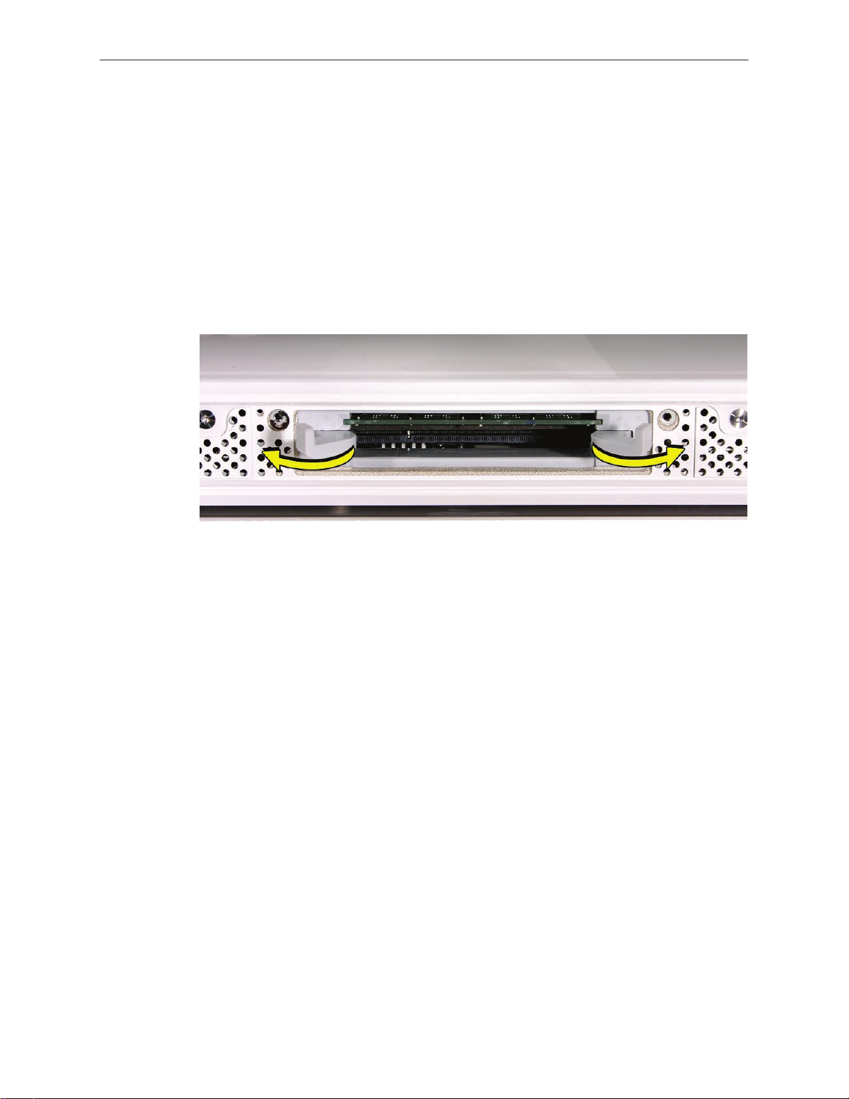
Removing the Memory
After removing the access door, touch the metal frame around the memory compartment to 1.
discharge any static electricity from your body.
Important: Always discharge static before you touch any parts such as the memory board.
To avoid generating static electricity, do not walk around the room until you have nished
replacing the memory.
Pull the two levers in the memory compartment toward you. If a memory module is installed 2.
in the slot, pulling the levers will dislodge it. Note: The levers are used to remove memory
not to install memory. Always install memory with your ngers.
Set the memory modules aside.3.
iMac (17-inch Late 2006) Take Apart — Memory 22
Page 23
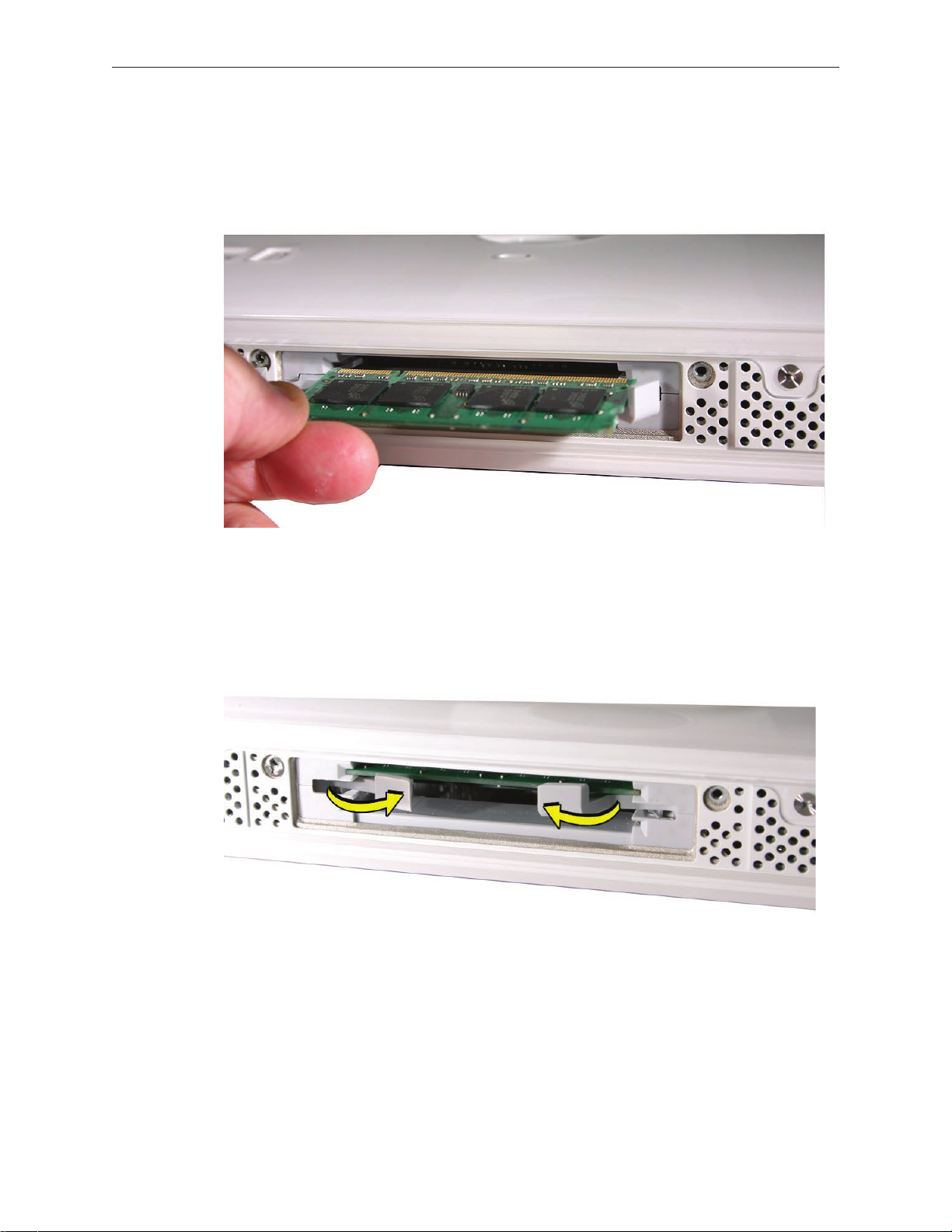
Replacing the Memory
Make sure the DIMM levers are all the way open. 1.
With the computer face down, orient the DIMM with the notch on the left. 2.
With your ngers, press the DIMM fully into the slot until you hear a click. After inserting the 3.
memory, fold the DIMM levers closed. There will be a slight resistance and you will hear a
click when they fold into the closed position.
Replace the access door on the memory compartment.4.
Use a Phillips #2 screwdriver to tighten the captive screws on the access door.5.
iMac (17-inch Late 2006) Take Apart — Memory 23
Page 24
Front Bezel
Tools
Access card tool 922-7172•
Torx T8 screwdriver•
Preliminary Steps
Before you begin, remove the access door and the memory.
Part Location
iMac (17-inch Late 2006) Take Apart — Front Bezel 24
Page 25
922-7011 (x3)
922-7749 (x1)
Removing the Front Bezel
1. With the bottom facing toward you use a T8 torx screwdriver to remove the four bezel
mounting screws. The screws are shown in the order they were removed, left to right.
Stand the computer upright.2.
Located the access card tool. Bend the upper quarter of the access tool card slightly to 3.
engage the front bezel latches. Note: Refer to AccessToolModication in the General
Information chapter if the bezel is dicult to open.
iMac (17-inch Late 2006) Take Apart — Front Bezel 25
Page 26
This picture shows how the access tool pushes the latch. Go on to the next step to use the 4.
tool.
Start on the left side (looking from the back of the unit). Insert the card to disengage the 5.
latch. Squeeze the top of the bezel, that will help take pressure o of the latch and enable it
to open easier. As the bezel releases, pull the bezel away from the rear housing.
iMac (17-inch Late 2006) Take Apart — Front Bezel 26
Page 27
Repeat step 5 to release the locking latch in the right corner. Again, pull the bezel away as 6.
the card releases the latch.
If the bezel won’t release, pull the bottom of the bezel out a bit and insert the access card 7.
again.
iMac (17-inch Late 2006) Take Apart — Front Bezel 27
Page 28
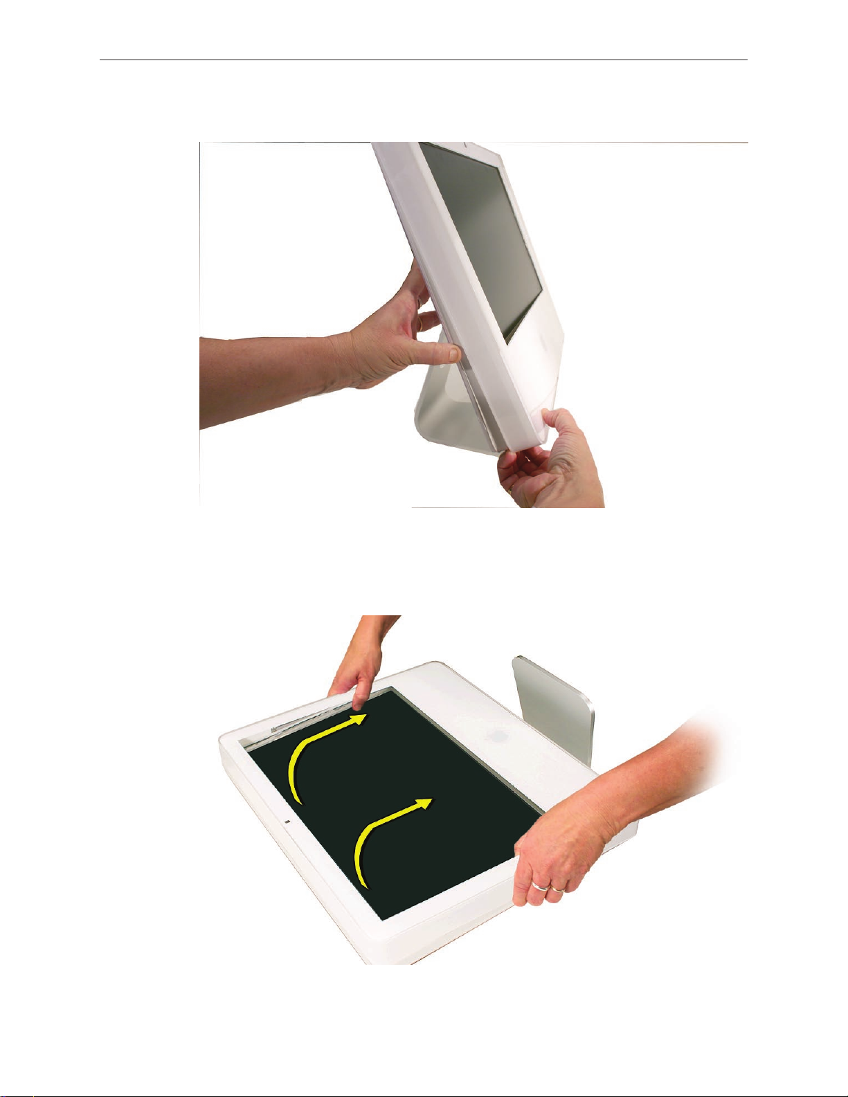
Repeat step 7 for the left side. 8.
Once the access card has been removed, it is safe to open the bezel. Position the unit on an 9.
ESD mat, with the bottom facing toward you. Caution: Make sure the memory levers are
closed and not protruding from the bezel when removing the bezel.
iMac (17-inch Late 2006) Take Apart — Front Bezel 28
Page 29
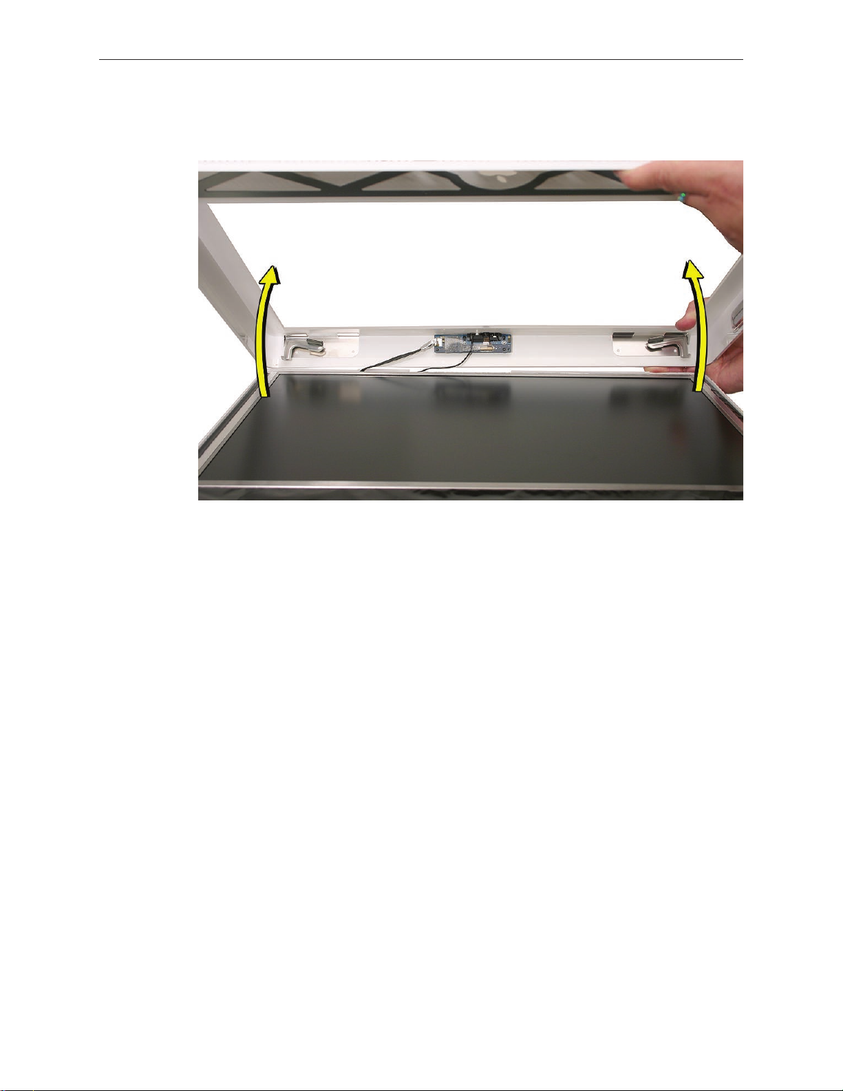
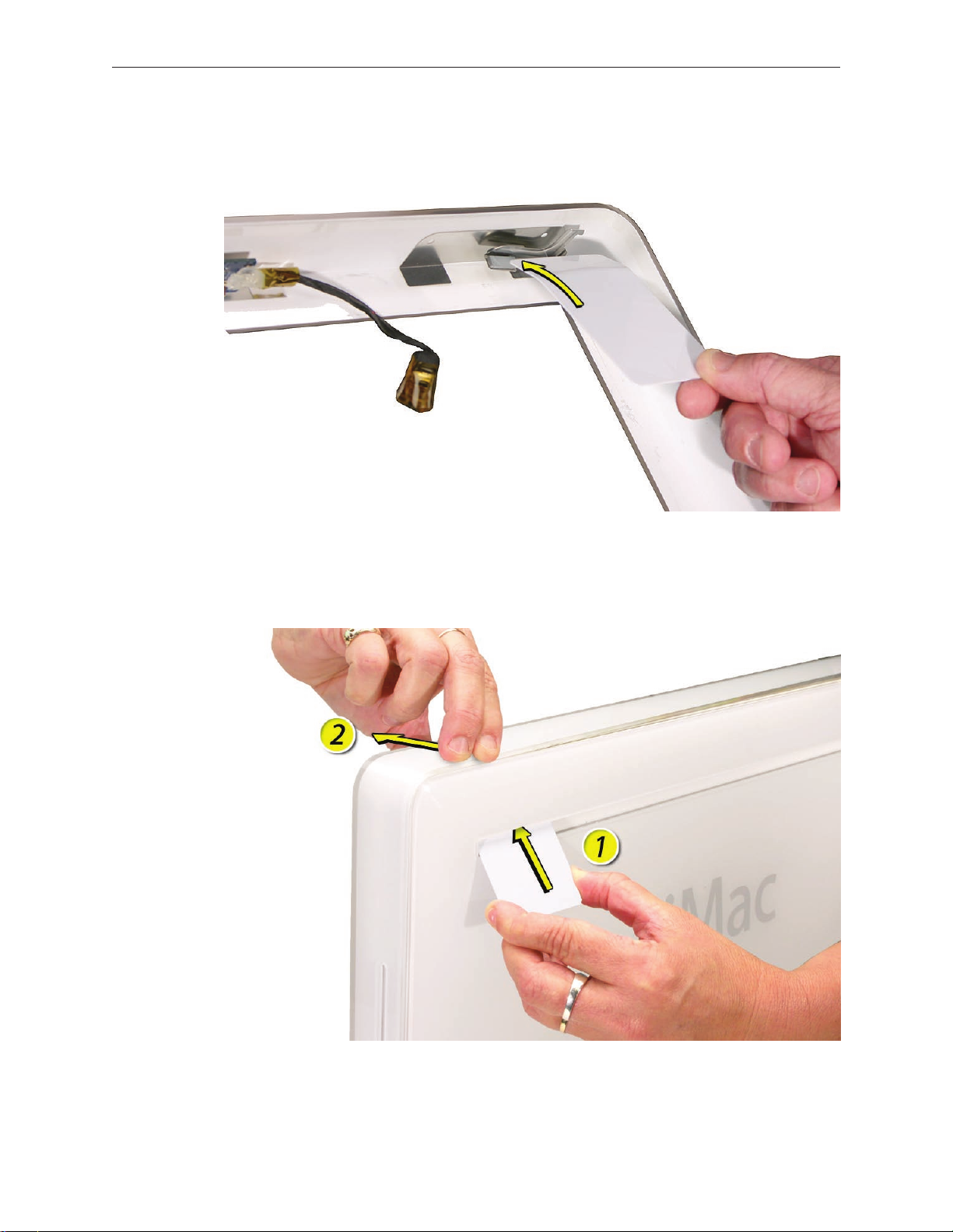
Lift the bottom of the front bezel straight up to remove it, and swing the bezel over onto its 10.
top edge. Disconnect the two cables attached to the top of the bezel.
iMac (17-inch Late 2006) Take Apart — Front Bezel 29
Page 30
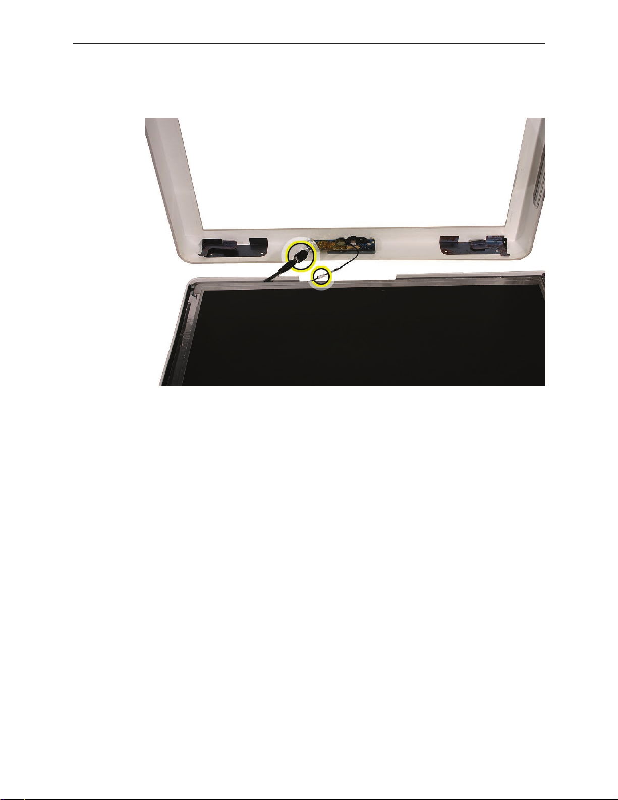
Swing the bezel up so you can disconnect the two camera board cables Remove the any 11.
kapton tape and disconnect the camera and microphone cables from the camera board..
If replacing a damaged front bezel, remove the camera board.12.
iMac (17-inch Late 2006) Take Apart — Front Bezel 30
Page 31

Replacing the Front Bezel
Position the front bezel near the top edge of the unit and connect the two camera board 1.
connectors.
Make sure the black EMI shielding along the top of the LCD panel is not in the way of the 2.
locking mechanisms when you lower the front bezel onto the computer. Use a black stick to
press (re-stick) the EMI shielding along the top of the panel.
Wrap the cables with kapton tape then tuck the cables neatly into the channel on the rear 3.
housing.
iMac (17-inch Late 2006) Take Apart — Front Bezel 31
Page 32

Make sure the memory ejector levers are in the closed position (as shown) before lowering 4.
the front bezel over the ejectors.
Continue to lower the font bezel down and press the top corners of the front bezel to 5.
connect the latches. Note: Check that the latches are connected by lifting the front bezel at
each corner.
Replace the four bezel screws along the bottom of the computer.6.
Replace the access door and tighten the two captive screws.7.
Install any removed DIMMS after the unit is fully assembled. 8. Important: Memory DIMMs
must be installed by hand. Do not use the memory ejector levers to install memory.
iMac (17-inch Late 2006) Take Apart — Front Bezel 32
Page 33

Camera Board
Tools
The only tool required for this procedure is a T6 screwdriver.
Preliminary Steps
Before you begin, follow steps for remove:
A• ccess door
M• emory
F• ront bezel
Part Location
iMac (17-inch Late 2006) Take Apart — Camera Board 33
Page 34

Removing the Camera Board
The camera board and cables are visible as you lift the front bezel o the computer. 1.
Remove any kapton tape wrapped around the cables. Disconnect the camera and 2.
microphone cables.
iMac (17-inch Late 2006) Take Apart — Camera Board 34
Page 35

922-7713
3. Using a T6 screwdriver, remove the two camera board mounting screws.
Pull the camera board straight out of the lens aperture opening in the bezel. 4.
iMac (17-inch Late 2006) Take Apart — Camera Board 35
Page 36

Replacing the Camera Board
Carefully insert the camera lens in the bezel opening. 1.
2. Install the camera board to the bezel with two T6 mounting screws.
922-7713
Replace the front bezel.3.
Replace the access door.4.
iMac (17-inch Late 2006) Take Apart — Camera Board 36
Page 37

Lower EMI Shield
Tools
Black stick (or other nonconductive nylon or plastic at-blade tool).•
Preliminary Steps
Before you begin, remove:
Access doo• r
Front beze• l
Part Location
iMac (17-inch Late 2006) Take Apart — Lower EMI Shield — 37
Page 38

Removing the Lower EMI Shield
Carefully peel the lower EMI shield o the bottom edge and side of the rear housing. Use a 1.
black stick to help peel back the shield.
If replacing a torn or damaged lower EMI shield, peel the lower EMI shield o the bottom 2.
edge of the display.
Replacing the Lower EMI Shield
Position the lower EMI shield over the bottom of the unit so that the holes in the shield are 1.
properly aligned.
Press the sticky, top edge of the EMI shield onto the bottom side of the display panel. The 2.
crease in the EMI shield should align with the edge of the panel.
Fold down the EMI shield and press it rmly over the bottom edge of the rear housing. Use a 3.
black stick to rub out wrinkles and ensure that the EMI shield adheres rmly along all edges.
Replace the front bezel.4.
Replace the access door.5.
iMac (17-inch Late 2006) Take Apart — Lower EMI Shield — 38
Page 39

IR Board
Tools
Torx T8 screwdriver (magnetized)•
Preliminary Steps
Before you begin, remove:
Access doo• r
Front beze• l
Lower EMI shiel• d
Part Location
iMac (17-inch Late 2006) Take Apart — IR Board 39
Page 40

Removing the IR Board
Disconnect the IR cable from the IR board. 1.
922-7010
2. Using a Torx T6 screwdriver, remove the two IR screws. Lift the IR board from its mounting
bracket.
iMac (17-inch Late 2006) Take Apart — IR Board 40
Page 41

Replacing the IR Board
Install the IR board and two T6 mounting screws.1.
Connect the IR cable to the IR board connector.2.
Replace the lower EMI shield.3.
Replace the front bezel.4.
Replace the access door.5.
iMac (17-inch Late 2006) Take Apart — IR Board 41
Page 42

AirPort Extreme Card
Tools
Torx T6 screwdriver (magnetized)•
Preliminary Steps
Before you begin, remove:
Access doo• r
Front beze• l
Lower EMI shiel• d
Part Location
iMac (17-inch Late 2006) Take Apart — AirPort Card 42
Page 43

Removing the AirPort Extreme Card
Disconnect the two antenna cables from the AirPort Extreme card. 1.
922-7010
2. Remove the two T6 screws from the AirPort Extreme card.
iMac (17-inch Late 2006) Take Apart — AirPort Card 43
Page 44

The card will spring up when the screws are removed. Grab the card from the connector end 3.
and pull the card from the socket on the logic board.
Replacing the AirPort Extreme Card
See the following section on compatibility to order the replacement part by EEE code.1.
Install the AirPort Extreme card into the logic board socket. 2.
Install the two T6 mounting screws securing the card to the logic board.3.
Connect the AirPort antenna cables to the connectors on the card.4.
Replace the lower EMI shield.5.
Replace the front bezel.6.
Replace the access door.7.
Checking Compatibility between AirPort Card and Logic Board
The iMac (Late 2006) computers were built with a number of logic boards and AirPort Extreme
cards. To avoid confusion identifying the correct logic board and AirPort Extreme card for the
system, refer to the table in this section which lists the corresponding EEE codes.
Locating the EEE Code
To locate the EEE code on the AirPort Extreme card, remove the card from the logic board. Turn
the card over, and look for the representative EEE code within the card’s serial number. Locate the
last four digits in the serial number. Drop the last digit (in this case, the letter “A”). The EEE code is
the next three digits. In this case it’s “VZL”, shown below.
iMac (17-inch Late 2006) Take Apart — AirPort Card 44
Page 45

To locate the EEE code on the logic board, locate the memory slot inside the computer. Locate
the last four digits in the serial number. Drop the last digit, in this case, the letter “A.” The EEE code
is the next three digits. In this case the EEE code is “WZH.”
EEE Code Table
Use the table below to identify the logic board and AirPort Extreme card EEE codes for the iMac
system. Order the correct service part based upon the corresponding EEE code. The table is
available in Knowledge Base article 305112-iMac(Late2006):AirPortCardDierences.
iMac Model Logic Board
Part #
iMac (17-inch Late
2006)
iMac (17-inch Late
2006)
661-4290,
Board , Logic,
2.0 GHz
661-4105,
Board , Logic,
2.0 GHz
Logic Board
EEE Code
XYA
XYB
XYC
VX6
VX7
VX8
AirPort
Extreme Card
Part #
661-4289,
B661-4289,
J661-4289,
KH661-4289,
PA661-4289,
Z661-4289
661-4060,
B661-4060,
J661-4060,
KH661-4060,
PA661-4060,
Z661-4060
AirPort
Extreme Card
EEE Code
WQX
WQY
WQZ
WR2
WR0
WR1
VZL
VZM
VZN
VZR
VZP
VZQ
iMac (17-inch Late 2006) Take Apart — AirPort Card 45
Page 46

iMac Model Logic Board
Part #
Logic Board
EEE Code
AirPort
Extreme Card
Part #
AirPort
Extreme Card
EEE Code
iMac (17-inch Late
2006)
iMac (17-inch Late
2006)
661-4106,
Board , Logic,
2.16 GHz
661-4291,
Board , Logic,
2.16 GHz
W4Y
W4Z
W50
XDH
XHE
XHF
661-4060,
B661-4060,
J661-4060,
KH661-4060,
PA661-4060,
Z661-4060
661-4289,
B661-4289,
J661-4289,
KH661-4289,
PA661-4289,
Z661-4289
VZL
VZM
VZN
VZR
VZP
VZQ
WQX
WQY
WQZ
WR2
WR0
WR1
iMac (17-inch Late 2006) Take Apart — AirPort Card 46
Page 47

Battery
Tools
Black stick•
Preliminary Steps
Before you begin, remove:
Access doo• r
Front beze• l
Lower EMI shiel• d
Part Location
iMac (17-inch Late 2006) Take Apart — Battery 47
Page 48

Removing the Battery
Using a black stick, pry the battery from the battery slot. 1.
Replacing the Battery
Slide the battery (with voltage information face up) into the battery holder. Press the battery 1.
into place.
Replace the lower EMI shield.2.
Replace the front bezel.3.
Replace the access door.4.
iMac (17-inch Late 2006) Take Apart — Battery 48
Page 49

iMac (17-inch Late 2006) Take Apart — Battery 49
Page 50

LCD Display
Tools
Torx T10 screwdriver•
Torx T6 screwdriver •
Black stick (or other nonconductive nylon or plastic at-blade tool)•
Preliminary Steps
Before you begin, remove:
Access doo• r
Front beze• l
Lower EMI shiel• d
Part Location
iMac (17-inch Late 2006) Take Apart — Display Panel 50
Page 51

Removing the LCD Display
Using the black stick, or access tool, carefully peel back the EMI shielding from the left, right, 1.
and bottom edges of the computer
922-7010
2. Using a Torx T6 screwdriver, remove the two LVDS cable connector screws. Disconnect the
LVDS display cable from the logic board.
iMac (17-inch Late 2006) Take Apart — Display Panel 51
Page 52

To the right of the battery is the inverter cable connector. Disconnect the inverter cable from 3.
the logic board.
922-7023
4. Using the access card or a black stick, peel the EMI tape away from each side of the panel.
Remove the four panel mounting screws with a T10 screwdriver.
iMac (17-inch Late 2006) Take Apart — Display Panel 52
Page 53

Pivot the panel up, as shown, then carefully peel the top edge of the panel away from the 5.
EMI shield. Note: Continue with steps 6-12 if you are replacing the display panel.
922-7158
Note: If replacing a bad LCD display, you will need to remove the lower EMI shield (if still
attached), the display panel mounting brackets, and the LVDS cable as follows.
Peel the lower EMI shield o the bottom edge of the display panel.6.
7. Using a torx T10 screwdriver, push the tape aside and remove two screws from the left side
panel mounting bracket. Repeat for the other side.
iMac (17-inch Late 2006) Take Apart — Display Panel 53
Page 54

Peel back the clear tape and disconnect the two inverter-to-display cable connectors. 8.
To access the LVDS cable connector, peel back the clear tape and the black mylar (if 9.
necessary). Pinch together the connector locking levers, and disconnect the LVDS cable
connector.
Return the panel to Apple. 10.
iMac (17-inch Late 2006) Take Apart — Display Panel 54
Page 55

Replacing the LCD Display
Replace the LVDS cable on the rear of the display panel. 1.
Secure the LVDS cable with clear tape and the black mylar. 2.
Replace the right panel mounting bracket on the display panel with two T8 screws.3.
Replace the left bracket on the display panel with two T8 screws. 4.
Connect the two inverter-to-display cable connectors and tape them to the back of the 5.
display panel.
iMac (17-inch Late 2006) Take Apart — Display Panel 55
Page 56

Turn over the panel. If the lower EMI shield was removed, reattach the lower EMI shield 6.
across the bottom of the panel.
Attach the three pieces of aluminum tape along the bottom of the panel. The tape comes 7.
with the replacement panel. The tape should attach to the panel on one side and to the
lower EMI shield on the other side.
Position the panel into the rear housing. Make sure the inverter cable and the LVDS cable are 8.
accessible and not tucked under the panel.
Secure the panel with four T10 mounting screws.9.
Connect the inverter cable connector to the logic board.10.
Connect the LVDS cable connector to the logic board and secure it with two T6 screws.11 .
Fold the EMI tape rmly over the left, top, and right edges of the display panel. Use the black 12.
stick to adhere the tape rmly and rub out wrinkles.
Replace the front bezel.13 .
Replace the access door.14.
iMac (17-inch Late 2006) Take Apart — Display Panel 56
Page 57

LVDS Display Cable
Tools
No tools are required.
Preliminary Steps
Before you begin, remove
Access doo• r
Front beze• l
Lower EMI shiel• d
LCD Displa• y
Part Location
iMac (17-inch Late 2006) Take Apart — LVDS Cable 57
Page 58

Remove the LVDS Cable
Locate the LVDS cable on the back side of the display panel. Remove the piece of tape that 1.
secures the cable to the panel.
Pinch together the connector locking levers, and disconnect the LVDS cable connector. 2.
iMac (17-inch Late 2006) Take Apart — LVDS Cable 58
Page 59

Replacing the LVDS Cable
Attach the LVDS cable on the back of the display panel as shown. 1.
If you are replacing the display, a piece of black mylar is enclosed in the box with the display 2.
module. The dotted lines below show the correct placement of the clear tape and black
mylar.
(
Replace the lower EMI shield.3.
Lower the display into place. Replace the four display screws.4.
iMac (17-inch Late 2006) Take Apart — LVDS Cable 59
Page 60

Replace the front bezel.5.
Replace the access door.6.
iMac (17-inch Late 2006) Take Apart — LVDS Cable 60
Page 61

Inverter
Tools
Flat-blade screwdriver•
Preliminary Steps
Before you begin, follow steps for removing the following:
Access doo• r
Front beze• l
Lower EMI shiel• d
LCD Displa• y
Part Location
iMac (17-inch Late 2006) Take Apart — Inverter 61
Page 62

Removing the Inverter
Remove three pieces of tape that secure the inverter cables to the back of the display panel, 1.
and disconnect the two white inverter connectors shown.
Using a at-blade screwdriver as shown, pry up the inverter to remove it from inside the 2.
display panel mounting bracket.
iMac (17-inch Late 2006) Take Apart — Inverter 62
Page 63

Replacing the Inverter
Insert the long, black inverter cable through a hole at the back center of the right mounting 1.
bracket, and press the sticky side of the replacement inverter onto the back edge of the
bracket.
Connect the inverter-to-display cables and tape them to the back of the display panel. 2.
.
Replace the display panel.3.
Replace the lower EMI shield.4.
Replace the front bezel.5.
Replace the access door.6.
iMac (17-inch Late 2006) Take Apart — Inverter 63
Page 64

Speakers
Tools
Torx T10 screwdriver (magnetized)•
Torx T6 screwdriver (magnetized)•
Preliminary Steps
Before you begin, follow steps for removing the following:
Access doo• r
Front beze• l
Lower EMI shiel• d
LCD Displa• y
Part Location
iMac (17-inch Late 2006) Take Apart — Speaker 64
Page 65

922-7067
922-7068
Removing the Speakers
1. Using a T10 torx screwdriver, remove the screws from the left and right speakers.
Replacement Note: The longer of the two speaker mounting screws is used to secure the
left speaker; the shorter screw secures the right speaker.
Lift up the right speaker. The speaker cable routes under the Bluetooth board. Remove the 2.
two T6 screws on the Bluetooth board. Lift the Bluetooth board to access the speaker cable.
iMac (17-inch Late 2006) Take Apart — Speaker 65
Page 66

Disconnect the speaker cable located to the right of the Bluetooth board.3.
Replacing the Speakers
Connect the speaker cable to the connector on the logic board. 1.
Route the speaker cable under the Bluetooth board. Replace the two T6 screws.2.
iMac (17-inch Late 2006) Take Apart — Speaker 66
Page 67

Install the speakers and position the speaker wire above the heatsink. 3.
Secure the right speaker with the shorter of the two mounting screws.4.
Secure the left speaker with the longer of the two mounting screws. 5.
Replace the display panel.6.
Replace the EMI shield.7.
Replace the front bezel.8.
Replace the access door.9.
iMac (17-inch Late 2006) Take Apart — Speaker 67
Page 68

Bluetooth Board
Tools
Torx T6 screwdriver (magnetized)•
Preliminary Steps
Before you begin, follow steps for removing the following:
Access doo• r
Front beze• l
Lower EMI shiel• d
LCD Displa• y
Speaker• s
Part Location
Note: The Bluetooth board is located under the right speaker.
iMac (17-inch Late 2006) Take Apart — Bluetooth Board
Page 69

922-7010
Remove the Bluetooth Board
1. Using a T6 torx screwdriver, remove the mounting screws from Bluetooth card and gently
disconnect the Bluetooth antenna from the connector on the card.
Lift the Bluetooth card straight up and o the logic board connector.2.
Replacing the Bluetooth Board
Connect the Bluetooth board to the logic board.1.
Attach the Bluetooth antenna to the Bluetooth board.2.
Replace the two T6 screws on the Bluetooth board. 3.
Connect the speaker cable connector to the logic board, 4.
Secure the right speaker with the smaller of the two mounting screws.5.
Secure the left speaker with the longer of the two mounting screws. 6.
Replace the display panel.7.
Replace the EMI shield.8.
Replace the front bezel.9.
Replace the access door.10.
iMac (17-inch Late 2006) Take Apart — Bluetooth Board
Page 70

Optical Drive
Tools
Torx T10 screwdriver (magnetized)•
Torx T6 screwdriver (magnetized)•
Needlenose pliers (with teeth)•
Preliminary Step
Before you begin, follow steps for removing the following:
Access doo• r
Front beze• l
Lower EMI shiel• d
LCD Displa• y
Part Location
iMac (17-inch Late 2006) Take Apart — Optical Drive 70
Page 71

922-6842
Removing the Optical Drive
1. Disconnect the sensor cable from the temperature sensor on top of the optical drive and
remove the two T10 screws from the optical drive clip on the logic board.
Note2. : Make sure to use a needlenose pliers with teeth to remove the optical drive. The pliers
must have a textured surface to properly grasp the optical drive release tabs.
iMac (17-inch Late 2006) Take Apart — Optical Drive 71
Page 72

Locate the black tabs at each side of the plastic optical drive mounting bracket. Starting at 3.
the release tab that is furthest from the logic board, grasp the tab with needlenose pliers,
and ex the tab toward the optical drive exible cable. (Note: This graphic shows a dierent
iMac model, but the removal procedure is the same for each model.) Use one nger
underneath the edge of the optical drive to gently lift up that corner of the drive.
Caution: Never press down on or grasp the body (silver) of the optical drive when removing
or installing it. Depressing the body of the optical drive could damage the mechanism. Grasp
the optical drive by its mounting bracket only.
iMac (17-inch Late 2006) Take Apart — Optical Drive 72
Page 73

Warning4. : iMac main logic boards returned with physical damage such as scratches, fractures,
or broken or missing components caused by improper servicing may be classied as
customer abuse. When using a tool to release the latches, be careful not to apply pressure to
the logic board or it may be damaged.
While avoiding the logic board, grasp the tab with needlenose pliers, and ex the tab toward
the optical drive. Use one nger underneath the rear edge of the optical drive to gently tilt
up the end of the drive and remove the optical drive out of the housing. Note: This graphic
shows a dierent iMac model, but the removal procedure is the same.
iMac (17-inch Late 2006) Take Apart — Optical Drive 73
Page 74

922-7656
Caution:5. Never press down on or grasp the body (silver) of the optical drive when removing
or installing it. Depressing the body of the optical drive could damage the mechanism. Grasp
the optical drive by its mounting bracket only.
Lift the rear of the drive and pull the front bezel of the drive straight back and out of the disc 6.
opening in the rear housing.
7. If replacing a bad optical drive, use a T6 torx screwdriver to remove two optical drive board
mounting screws. Disconnect and keep the board for installation on the replacement drive.
If replacing a bad optical drive the replacement drive will have a new sensor installed. 8.
iMac (17-inch Late 2006) Take Apart — Optical Drive 74
Page 75

Replacing the Optical Drive
If removed, install the optical drive board to the optical drive with two T6 screws.1.
Insert the optical drive “bezel-end-rst” into the opening in the housing. Be sure to align the 2.
two guide holes in the front bezel with guide posts at each end of the bezel opening.
Push down on the black mounting bracket to lock the optical drive securely into place on
the chassis.
Caution: Never press down on or grasp the body (silver) of the optical drive when removing
or installing it. Depressing the body of the optical drive could damage the mechanism. Grasp
the optical drive by its mounting bracket only.
Secure the optical drive board to the logic board with the metal mounting clip and two T10 3.
screws.
Connect the optical cable to the optical sensor on one end and to the logic board on the 4.
other end.
Replace the display panel.5.
Replace the lower EMI shield.6.
Replace the front bezel.7.
Replace the access door.8.
iMac (17-inch Late 2006) Take Apart — Optical Drive 75
Page 76

iMac (17-inch Late 2006) Take Apart — Optical Drive 76
Page 77

Hard Drive
Tools
Torx T8 screwdriver (magnetized)•
Flat-blade screwdriver•
Preliminary Steps
Before you begin, follow steps for removing the following:
Access doo• r
Front beze• l
Lower EMI shiel• d
LCD Displa• y
Part Location
iMac (17-inch Late 2006) Take Apart — Hard Drive 77
Page 78

Remove the Hard Drive
Disconnect the hard drive sensor from the top of the hard drive. 1.
Position yourself at the base of the computer closest to the stand.2.
Pull in on the edge of the mounting bracket until you feel it release from the chassis. Pull 3.
HARD! The hard drive bracket will release on the end near your hands.
iMac (17-inch Late 2006) Take Apart — Hard Drive 78
Page 79

Disconnect the hard drive power and data cables. Set the hard drive aside. 4.
Transfer the temperature sensor from the bad drive to the replacement hard drive. 5. Note:
If you are replacing a hard drive, also remove the mounting bracket and the mounting pins
shown in the following steps.
iMac (17-inch Late 2006) Take Apart — Hard Drive 79
Page 80

922-7019
922-7001
6. Using a T8 torx screwdriver, remove two screws and the mounting bracket from the drive.
7. Using a T8 torx screwdriver, remove two mounting pins from the other side of the drive.
iMac (17-inch Late 2006) Take Apart — Hard Drive 80
Page 81

Replacing the Hard Drive
Install the temp sensor on the replacement drive.1.
If necessary, install two mounting pins on side of the hard drive mounting bracket.2.
If necessary, install the mounting bracket to the top of the hard drive with two screws.3.
Connect the temp sensor cable to sensor and to the logic board connector. 4.
Connect the hard drive power and data cables.5.
Insert the hard drive mounting pins and position the drive on the chassis. Make sure the 6.
hard drive power and data cables are routed correctly and don’t get pinched as you lower
the drive into the chassis. Press down on the mounting bracket to lock it in place on the
chassis.
Replace the display panel.7.
Replace the lower EMI shield.8.
Replace the front bezel.9.
Replace the access door.10.
iMac (17-inch Late 2006) Take Apart — Hard Drive 81
Page 82

DC-DC Board
Tools
Torx T10 screwdriver (magnetized)•
Preliminary Steps
Before you begin, remove:
Access doo• r
Front beze• l
Lower EMI shiel• d
LCD Displa• y
Part Location
iMac (17-inch Late 2006) Take Apart — DC-DC Board
Page 83

Removing the DC-DC Board
Disconnect the power supply cable and the DC power cable from the DC-DC board. 1.
922-7159 (bottom
left)
922-7157
(bottom right)
922-6842
2. Using a T10 torx screwdriver, remove the two self-tapping screw from the bottom corners of
the board and the machine screw in the top right corner.
iMac (17-inch Late 2006) Take Apart — DC-DC Board
Page 84

Replacing the DC-DC Board
Position the DC-DC board and install the long black self-tapping screw in the lower right 1.
corner, the other self-tapping screw in the lower left corner, and the machine screw in the
top right corner.
Connect the DC power cable and the power supply cable to connectors on the DC-DC board.2.
Replace the display panel.3.
Replace the lower EMI shield.4.
Replace the front bezel.5.
Replace the memory access door.6.
iMac (17-inch Late 2006) Take Apart — DC-DC Board
Page 85

Power Supply
Tools
Torx T8 screwdriver (magnetized)•
Torx T10 screwdriver (magnetized)•
Black stick•
Preliminary Steps
Before you begin, follow steps for removing the following:
Access doo• r
Front beze• l
Lower EMI shiel• d
LCD Displa• y
Hard Driv• e
Part Location
iMac (17-inch Late 2006) Take Apart — Power Supply 85
Page 86

About the Power Supply
Warning: When the iMac is under power, be aware that the power supply contains high voltages
that pose a potential hazard to your personal safety. Never work on or near the power supply
with the unit powered on, and as a further precaution always make sure the unit is unplugged
when working on it with the front bezel removed.
WARNING: HIGH VOLTAGE
Text or photographs marked by this symbol indicate that a potential hazard to your personal
safety exists from a high voltage source.
The AC/DC power supply board is a high voltage source with the unit under power, and remains
powered up whenever the system is plugged in, whether or not the system is turned on. Use
extreme caution when troubleshooting the system with the front bezel removed.
Disconnect power to the system before performing maintenance.•
Don’t work alone. In the even of an electrical shock it is important to have another •
individual present who can provide assistance.
Keep one hand in your pocket when working on any iMac that is plugged in. This will •
help ensure that your body does not provide a path to ground in the event that you
accidentally make contact with the line voltage.
Don’t wear jewelry, watches, necklaces, or other metallic articles that could present a risk •
if they accidentally make contact with the power supply circuitry.
iMac (17-inch Late 2006) Take Apart — Power Supply 86
Page 87

Removing the Power Supply
1. WARNING: HIGH VOLTAGE
Disconnect the AC power inlet connector on the right side of the power supply board. The
power supply to AC cable connector is tucked under the chassis. Pry the cable from under
the chassis with a black stick. Next, disconnect the power supply-to-DC board on the left
side the DC-DC board.
922-7066 (x1)
922-7159 (x3)
2. Using a T10 screwdriver, remove the three self-tapping screws (top right and the two on the
left side) and the one machine screw on the lower right corner of the board.
iMac (17-inch Late 2006) Take Apart — Power Supply 87
Page 88

Remove the power supply from the enclosure.3.
If you are replacing the power supply-to-logic board cable, disconnect the cable from the 4.
logic board and remove the cable from the enclosure.
Note: To disconnect the cable, do the following:
• Rotate the computer so that the stand is away from you.
• Locate the power supply connector underneath the logic board.
• Pinch the tab and pull the connector to the left to release the connector.
iMac (17-inch Late 2006) Take Apart — Power Supply 88
Page 89

Replacing the Power Supply
1. WARNING: HIGH VOLTAGE
Position the power supply loosely in its mounting location.
Connect the power supply-to-AC power inlet cable. Tuck the cable beneath the chassis and 2.
away from the hard drive bay.
Connect the DC-DC cable to the power supply board and to the underside of the logic board 3.
(if previously disconnected).
Install the four power supply screws, starting with the machine screw in the lower right 4.
corner of the power supply. Then install the other screws (see photo above for locations).
Replace the hard drive.5.
Replace the display panel.6.
Replace the lower EMI shield.7.
Replace the front bezel.8.
Replace the access door.9.
iMac (17-inch Late 2006) Take Apart — Power Supply 89
Page 90

Logic Board
Tools
Torx T10 screwdriver (magnetized)•
Torx T6 screwdriver (magnetized)•
Preliminary Steps
Before you begin, follow steps for removing the following:
Access doo• r
Front beze• l
Lower EMI shiel• d
LCD Displa• y
Hard Driv• e
O• ptical drive
Bluetooth Board•
Speaker• s
Memor• y
Part Location
iMac (17-inch Late 2006) Take Apart — Logic Board 90
Page 91

Removing the Logic Board
Disconnect the ten cables from their connectors on the logic board. 1.
Using a T10 torx screwdriver, remove the screws from the logic board. The locations of the 2.
three self-tapping screws are marked by and “S” in the photo. The remaining three screws, are
machine screws; they are marked with an “M”. Note: Transfer the small metal grounding
(located two screws below the battery) clip to the replacement logic board.
iMac (17-inch Late 2006) Take Apart — Logic Board 91
Page 92

Rotate the unit so the top of the rear housing is facing you. With a black stick, disconnect the 3.
power supply cable on the underside of the logic board.
Pull the board toward you and gently lift the board up. 4. Note: The I/O ports t tightly into the
port hole openings on the rear cover. You may have to wiggle with the board to free the
ports from the rear cover.
iMac (17-inch Late 2006) Take Apart — Logic Board 92
Page 93

Replacing the Logic Board
Note: iMac Firmware Update 1.2 (or later) Required
For proper performance and reliability of the Intel Core 2 Duo processors, apply the iMac
rmware update after replacing the logic board. The rmware update also allows Apple service
to consolidate two logic boards. The 661-4105 logic board will replaced by 661-4290 and the
661-4106 will be replaced by the 661-4291.
See the following section on compatibility to order the replacement part by EEE code.1.
Route all the cables so they are o to the side and out of the way of the logic board. Lower 2.
the logic board into the rear housing. Connect the DC power cable on the underside of the
board.
iMac (17-inch Late 2006) Take Apart — Logic Board 93
Page 94

Check that the screw holes are aligned with the screw mounts in the chassis. 3. Replacement
Note: The logic board should rest on the screw mounts without any binding or bowing—if it
doesn’t, adjust any cables that are interfering with the logic board. Reconnect the ten logic
board cables.
Secure the logic board by installing the machine screws rst and then the self-tapping 4.
screws, marked with an “S”.
iMac (17-inch Late 2006) Take Apart — Logic Board 94
Page 95

Install the optical drive.5.
Replace the hard drive.6.
Replace the speakers.7.
Connect the AirPort antennas to the AirPort Extreme card. 8. Replacement Note: Add new info
here
Replace the Bluetooth board.9.
Connect the Bluetooth antenna to the Bluetooth board.10.
Replace the display panel.11.
Replace the lower EMI shield.12.
Replace the front bezel.13 .
Replace the memory.14.
Replace the memory access door.15 .
iMac (17-inch Late 2006) Take Apart — Logic Board 95
Page 96

Checking Compatibility between AirPort Card and Logic Board
The iMac (Late 2006) computers were built with a number of logic boards and AirPort Extreme
cards. To avoid confusion identifying the correct logic board and AirPort Extreme card for the
system, refer to the table in this section which lists the corresponding EEE codes.
Locating the EEE Code
To locate the EEE code on the AirPort Extreme card, remove the card from the logic board. Turn
the card over, and look for the representative EEE code within the card’s serial number. Locate the
last four digits in the serial number. Drop the last digit (in this case, the letter “A”). The EEE code is
the next three digits. In this case it’s “VZL”, shown below.
iMac (17-inch Late 2006) Take Apart — Logic Board 96
Page 97

To locate the EEE code on the logic board, locate the memory slot inside the computer. Locate
the last four digits in the serial number. Drop the last digit, in this case, the letter “A.” The EEE code
is the next three digits. In this case the EEE code is “WZH.”
iMac (17-inch Late 2006) Take Apart — Logic Board 97
Page 98

EEE Code Table
Use the table below to identify the logic board and AirPort Extreme card EEE codes for the iMac
system. Order the correct service part based upon the corresponding EEE code. The table is
available in Knowledge Base article 305112-iMac(Late2006):AirPortCardDierences.
iMac Model Logic Board
Part #
iMac (17-inch Late
2006)
iMac (17-inch Late
2006)
iMac (17-inch Late
2006)
iMac (17-inch Late
2006)
661-4290,
Board , Logic,
2.0 GHz
661-4105,
Board , Logic,
2.0 GHz
661-4106,
Board , Logic,
2.16 GHz
661-4291,
Board , Logic,
2.16 GHz
Logic Board
EEE Code
XYA
XYB
XYC
VX6
VX7
VX8
W4Y
W4Z
W50
XDH
XHE
XHF
AirPort
Extreme Card
Part #
661-4289,
B661-4289,
J661-4289,
KH661-4289,
PA661-4289,
Z661-4289
661-4060,
B661-4060,
J661-4060,
KH661-4060,
PA661-4060,
Z661-4060
661-4060,
B661-4060,
J661-4060,
KH661-4060,
PA661-4060,
Z661-4060
661-4289,
B661-4289,
J661-4289,
KH661-4289,
PA661-4289,
Z661-4289
AirPort
Extreme Card
EEE Code
WQX
WQY
WQZ
WR2
WR0
WR1
VZL
VZM
VZN
VZR
VZP
VZQ
VZL
VZM
VZN
VZR
VZP
VZQ
WQX
WQY
WQZ
WR2
WR0
WR1
iMac (17-inch Late 2006) Take Apart — Logic Board 98
Page 99

CPU Fan
Tools
No tools are required to remove the CPU fan.
Preliminary Steps
Before you begin, follow steps for removing the following:
Access doo• r
Front beze• l
Lower EMI shiel• d
LCD Displa• y
Hard Driv• e
O• ptical drive
Speaker• s
Memor• y
Logic Board•
Part Location
iMac (17-inch Late 2006) Take Apart — CPU Fan 99
Page 100

Removing the CPU Fan
Lift the CPU fan o the white mounting posts. 1.
Replacing the CPU Fan
Align the CPU fan with the two mounting posts in the rear housing, and push it straight 1.
down onto the posts. Note: Route the antenna cable under the fan (as shown above), but
pull it aside (to the left side) when installing the logic board.
Replace the logic board. 2.
Connect the CPU fan cable and the rest of the cables to the logic board.3.
Replace the speakers.4.
Replace the display panel.5.
Replace the lower EMI shield.6.
Replace the front bezel.7.
Replace the memory.8.
Replace the access door.9.
iMac (17-inch Late 2006) Take Apart — CPU Fan 100
 Loading...