


 Loading...
USER’S GUIDE network management card
®
Contents
Introduction 1
Product Description . . . . . . . . . . . . . . . . . . . . . . . . . . . . . . . . . . 1
Internal Management Features. . . . . . . . . . . . . . . . . . . . . . . . . . . 3
Front Panel . . . . . . . . . . . . . . . . . . . . . . . . . . . . . . . . . . . . . . . . 5
Watchdog Features . . . . . . . . . . . . . . . . . . . . . . . . . . . . . . . . . . 7
Control Console 8
How To Log On . . . . . . . . . . . . . . . . . . . . . . . . . . . . . . . . . . . . . 8
How to Recover from a Lost Password. . . . . . . . . . . . . . . . . . . . . 11
Main Screen. . . . . . . . . . . . . . . . . . . . . . . . . . . . . . . . . . . . . . . 12
Control Console Menus . . . . . . . . . . . . . . . . . . . . . . . . . . . . . . . 15
Web Interface 18
Introduction . . . . . . . . . . . . . . . . . . . . . . . . . . . . . . . . . . . . . . 18
How to Log On . . . . . . . . . . . . . . . . . . . . . . . . . . . . . . . . . . . . 20
Summary Page . . . . . . . . . . . . . . . . . . . . . . . . . . . . . . . . . . . . . 22
Navigation Menu . . . . . . . . . . . . . . . . . . . . . . . . . . . . . . . . . . . 24
Network Menu 28
Introduction . . . . . . . . . . . . . . . . . . . . . . . . . . . . . . . . . . . . . . 28
Option Settings . . . . . . . . . . . . . . . . . . . . . . . . . . . . . . . . . . . . 29
System Menu 35
Introduction . . . . . . . . . . . . . . . . . . . . . . . . . . . . . . . . . . . . . . 35
Option Settings . . . . . . . . . . . . . . . . . . . . . . . . . . . . . . . . . . . . 37
DC Power Plant & Device Manager Menus 41
Status Options . . . . . . . . . . . . . . . . . . . . . . . . . . . . . . . . . . . . . 41
Management Options . . . . . . . . . . . . . . . . . . . . . . . . . . . . . . . . 44
i

USER’S GUIDE network management card
®
Event-Related Menus 66
Introduction . . . . . . . . . . . . . . . . . . . . . . . . . . . . . . . . . . . . . . 66
Event Log . . . . . . . . . . . . . . . . . . . . . . . . . . . . . . . . . . . . . . . . 68
Event Actions (Web Interface only) . . . . . . . . . . . . . . . . . . . . . . . 72
Event Recipients. . . . . . . . . . . . . . . . . . . . . . . . . . . . . . . . . . . . 75
E-mail Feature . . . . . . . . . . . . . . . . . . . . . . . . . . . . . . . . . . . . . 76
How to Configure Individual Events . . . . . . . . . . . . . . . . . . . . . . 80
Data Menu (Web Interface Only) 81
Log Option . . . . . . . . . . . . . . . . . . . . . . . . . . . . . . . . . . . . . . . 81
Configuration Option . . . . . . . . . . . . . . . . . . . . . . . . . . . . . . . . 82
Security 83
Security Features . . . . . . . . . . . . . . . . . . . . . . . . . . . . . . . . . . . 83
Authentication . . . . . . . . . . . . . . . . . . . . . . . . . . . . . . . . . . . . . 85
Troubleshooting 86
Management Card . . . . . . . . . . . . . . . . . . . . . . . . . . . . . . . . . . 86
Product Information 88
Warranty and Service . . . . . . . . . . . . . . . . . . . . . . . . . . . . . . . . 88
Life-Support Policy . . . . . . . . . . . . . . . . . . . . . . . . . . . . . . . . . . 90
Specifications. . . . . . . . . . . . . . . . . . . . . . . . . . . . . . . . . . . . . . 92
Index 93
APC Worldwide Customer Support 101
ii

USER’S GUIDE network management card
®
Introduction
Product Description
Features
The APC AP9617 Network Management Card EX is a web-based management product that uses multiple, open standards such as Telnet, HTTP, and SNMP to provide full management of supported devices:
•The following is a list of some of this Management Card’s features:
–Provides a Data Log accessible by FTP or a Web browser.
–Provides an Event Log accessible by Telnet, FTP, or a Web browser
–Detects connection speed of 10/100 MB per second.
–Generates e-mail notifications for DC Power Plant events and system events.
–Limits SNMP traps and e-mail notifications based on the severity level of the DC Power Plant or system events
–For Magnum models, can be managed through InfraStruXure Manager.
Initial set-up
You must define three TCP/IP settings for the Network Management Card before it can operate on the network.
•IP address of the Management Card
•Subnet mask
•IP address of the default gateway
To configure the TCP/IP settings, see the Network Management Card Quick-Start Manual (.\doc\en\Qckguide), provided in printed form, and in PDF on the APC Network Management Card utility CD.
1
USER’S GUIDE network management card
®
Network management features
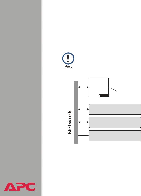
The Management Card can perform a variety of tasks. The figure that follows identifies and briefly describes the network management applications that can work with a DC Power Plant that connects to the network through the Management Card.
The APC Management Card Wizard identified in the following figure can be used to configure multiple Management Cards, either serially or over the network. It cannot be used to download firmware upgrades.
UDP
FTP |
DC Power |
|
||
HTTP |
Plant |
The Management Card connects the DC Power Plant to the network. |
||
SNMP |
|
|
||
SNMP |
|
|
Uses SNMP OIDs to provide SETs and |
|
MIB Browser |
||||
|
||||
|
GETs on a DC Power Plant. |
|||
|
|
|
||
HTTP |
Web Browser |
Provides a graphical UI to the DC |
||
|
Power Plant through a standard Web |
|||
|
|
browser. |
FTP |
Management Card Wizard |
Configures multiple Management Cards |
|
||
|
over a network. |
|
|
|
2

USER’S GUIDE network management card
®
Internal Management Features
Overview
The Management Card has two internal interfaces (control console and Web interface) which provide menus with options that allow you to manage the DC Power Plant and the Management Card. The Management Card’s SNMP interface also allows you to use an SNMP browser with the PowerNet® Management Information Base (MIB) to manage the DC Power Plant.
For more information about the Management Card’s internal user interfaces, see Control Console and Web Interface.
To use the PowerNet MIB with an SNMP browser, see the
PowerNet® SNMP Management Information Base (MIB)
Reference Guide (\doc\en\Dcmibgde.pdf), which is provided on See also the APC Network Management Card utility CD.
Access priority for logging on
Only one user at a time can log onto the Management Card to use its internal user interface features. The priority for access is as follows:
•Local access to the control console from a computer with a direct serial connection to the Management Card always has the highest priority.
•Telnet access to the control console from a remote computer has priority over Web access.
•Web access either directly or through the InfraStruXure Manager (for InfraStruXure-compatible products), has the lowest priority.
f
For information about how SNMP access to the Management Card is controlled, see SNMP.
3

USER’S GUIDE network management card
®
Types of user accounts
The Management Card has two levels of access (Administrator and Device Manager), both of which are protected by Password and User Name requirements.
•An Administrator can use all of the management menus available in the control console and the Web interface. The Administrator’s default
User Name and Password are both apc.
•A Device Manager can use only these menus:
–The Device Manager menu and its sub-menus in the control console, and all menus in the top section of the navigation panel of the Web Interface (System, Power Modules, Distribution, Batteries, I/O)
–the Log option in the Events menu and in the Data menu in the Web interface. (A Device Manager can also access the Event Log in the control console by pressing CTRL-L)
A Device Manager cannot access the Network menu or the System menu that are in the second part of the navigation panel in the Web interface and are sub-menus of the main Control Console menu in the control console.
The Device Manager’s default User Name is device, and the default
Password is apc.
For information about how to set Administrator and Device
Manager User Name and Password settings, see User
Manager.
4
USER’S GUIDE network management card
®
Front Panel
Introduction
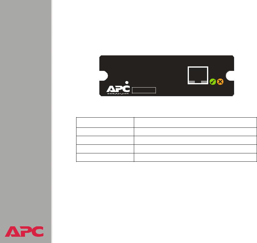
The front-panel features of the Network Management Card (AP9617) include Status LEDs, a Reset button, and a 10/100Base-T connector.
10/100Base-T
Reset |
Link - RX/TX |
Status |
|
10/100 |
|
|
Smart Slot AP9617 Network Management Card EX |
|
m |
|
|
Features |
|
|
Feature |
Description |
|
Reset button |
Resets the Management Card while power remains on. |
|
10/100 Base-T connector |
Connects the Management Card to the Ethernet network. |
|
Link-RX/TX (10/100) LED |
See Link-RX/TX (10/100) LED. |
|
Status LEDs |
See Status LEDs. |
|
5

USER’S GUIDE network management card
®
Link-RX/TX (10/100) LED
This LED indicates the network status.
Condition |
Description |
|
|
Off |
Either the Management Card is receiving no network traffic, or the |
|
device which connects the Management Card to the network is |
|
turned off or not operating correctly. |
|
|
Flashing Green |
The Management Card is receiving data packets from the network |
|
at 10 Megabits per second (Mbps). |
|
|
Flashing Orange |
The Management Card is receiving data packets from the network |
|
at 100 Megabits per second (Mbps). |
|
|
Status LEDs
These LEDs indicate the Management Card’s status.
Condition |
Description |
|
|
Off |
The Management Card has no power. |
|
|
Solid Green |
The Management Card has valid TCP/IP settings. |
|
|
Flashing Green |
The Management Card does not have valid TCP/IP settings.1 |
|
|
Solid Orange |
A hardware failure has been detected in the Management Card. |
|
Contact APC Worldwide Customer Support. |
|
|
Flashing Orange |
The Management Card is making BOOTP2 requests. |
|
|
1.If you do not use a BOOTP server, see the Network Management Card Quick-Start Manual (.\doc\en\Qckguide) provided in printed format and in PDF on the APC Network Management Card utility CD for information about how to configure the Management Card’s TCP/IP settings.
2.To use a BOOTP server, see the Management Card Addendum (.\doc\Addendum.pdf) on the APC Network Management Card utility CD.
6

USER’S GUIDE network management card
®
Watchdog Features
Overview
To detect internal problems and recover from unanticipated inputs, the Management Card uses internal, system-wide watchdog mechanisms. When it reboots itself to recover from an internal problem, a System:
Warmstart event is recorded in the Event Log.
Network interface watchdog mechanism
The Management Card implements internal watchdog mechanisms to protect itself from becoming inaccessible over the network. For example, if the Management Card does not receive any network traffic for 9.5 minutes (either direct traffic, such as SNMP, or broadcast traffic, such as an Address Resolution Protocol [ARP] request), it assumes that there is a problem with its network interface and reboots itself.
Resetting the network timer
To ensure that the Management Card does not reboot if the network is quiet for 9.5 minutes, the Management Card attempts to contact the Default Gateway every 4.5 minutes. If the gateway is present, it responds to the Management Card, and that response restarts the 9.5-minute timer. If your application does not require or have a gateway, specify the IP address of a computer that is running on the network most of the time and is on the same subnet. The network traffic of that computer will restart the 9.5-minute timer frequently enough to prevent the Management Card from rebooting.
7

USER’S GUIDE network management card
®
Control Console
How To Log On
Overview
You can use either a local (serial) connection, or a remote (Telnet) connection with a computer on the Management Card’s subnet to access the control console.
Use case-sensitive User Name and Password entries to log in (by default, apc and apc, for an Administrator, or device and apc, for a Device Manager).
If you cannot remember your User Name or Password, see How to Recover from a Lost Password.
Remote access to the control console
You can use Telnet to log into the control console from any computer on the same subnet as the Management Card.
1.At a command prompt, type telnet and the Management Card’s System IP address, and then press ENTER. For example:
telnet 139.225.6.133
2.Enter your User Name and Password.
8
USER’S GUIDE network management card
®
Local access to the control console
You can use a local computer that connects to the Management Card through the Management Card’s serial port. The type of cable to use depends on the location of the Management Card in the DC Power Plant:
•Type 1: The Management Card is an integrated part of the DC System Controller. The DC System Controller front panel has the following connectors:
–A female DB-9 connector for connection to the control console.
–An RJ-45 10/100BaseT connector for connection to the network. For Type 1 equipment, use the straight-through serial cable (940-0085 or 0129-6) supplied with the DC Power Plant.
•Type 2: The Management Card is not a part of the DC System Controller. It is installed separately from the controller. The female DB-9 connector for connection to the control console is next to the Management Card.
For Type 2 equipment use a smart-signaling (advanced signaling) cable (940-0024 or 940-1524) supplied with the DC Power Plant.
To connect Type 1 equipment:
1.Select a serial port at the local computer, and disable any service that uses that port.
2.Use the Type 1 cable (940-0085 or 0129-6) to connect the selected port to the serial port on the DC System Controller.
9

USER’S GUIDE network management card
®
To connect Type 2 equipment:
1.Select a serial port at the local computer, and disable any service that uses that port.
2.Use the smart-signaling (advanced signaling) cable (940-0024 or 940-1524) to connect the selected port to the serial port on the mounting bracket of the Management Card.
Do not attach the cable to the serial port on the front panel of the DC System Controller
To continue the procedure for either type of equipment:
3.Run a terminal program (such as HyperTerminal®), and configure the selected port for 2400 bps, 8 data bits, no parity, 1 stop bit, and no flow control, and save the changes.
4.Press ENTER to display the User Name prompt.
5.Enter your user name and, at the Password prompt, your password.
10

USER’S GUIDE network management card
®
How to Recover from a Lost Password
You can use a local computer that connects to the Management Card through the serial port at the Management Card’s mounting bracket to access the control console.
1.Select a serial port at the local computer, and disable any service which uses that port.
2.Use the type 1 or type 2 serial cable as described in Local access to the control console to connect the selected port to the Management Card’s serial port.
3.Run a terminal program (such as HyperTerminal®), and configure the selected port for 2400 bps, 8 data bits, no parity, 1 stop bit, and no flow control, and save the changes.
4.Press ENTER to display the User Name prompt.
5.Press the Reset button on the Management Card, which causes the Management Card to restart, a process that typically takes approximately 15 seconds.
6.Press ENTER as many times as necessary to redisplay the User Name prompt, then use apc for the user name and password. (If you take longer than 30 seconds to log on after the User Name prompt is redisplayed, you must start the login procedure again at step 4.)
7.From the Control Console menu, select System, then User Manager.
8.Select Administrator, and change the User Name and Password settings, both of which are now defined as apc.
9.Press CTRL-C and log off.
Reconnect any cable that you disconnected in step 2 and restart any service that you disabled in step 1.
11

USER’S GUIDE network management card
®
Main Screen
Example main screen
The following is an example of the screen that appears when you log onto the control console at a Network Management Card (AP9617).
User Name: apc
Password : ***
American Power Conversion |
Network Management Card AOS |
v1.0.7 |
<c> Copyright 2004 All Rights Reserved |
MX28B DC APP |
v1.1.1 |
-------------------------------------------------------------------------------
Name |
: Plant1 |
|
Date: 04/15/2004 |
Contact |
: Tom_Adams |
Time: 05:49:30 |
|
Location |
: TestLab |
|
User: Administrator |
Up Time |
: 1 Day 4 |
Hours 5 Minutes |
Stat: P+ N+ A+ |
DC Power Plant : No Alarms Present
-------- Control Console ------------------------------------------------------
1- Device Manager
2- Network
3- System
4- Logout
<ESC>- Main Menu, <ENTER>- Refresh, <CTRL-L>- Event Log
>
12

USER’S GUIDE network management card
®
Information and status fields
Main screen information fields.
•Two fields identify the APC operating system (AOS) and application (APP) firmware versions. The application firmware uses a name that identifies the type of DC Power Plant that the Management Card connects to the network. In the Example main screen, the Management Card uses the application firmware for the DC Power Plant.
Network Management Card AOS |
v1.0.7 |
MX28B DC APP |
v1.1.1 |
•Three fields identify the system Name, Contact, and Location values.
Name : Plant1
Contact : Tom_Adams
Location : TestLab
To set the Name, Contact, and Location values, see
System Menu.
•An Up Time field reports how long the Management Card has been running since it was last turned on or reset.
Up Time : 1 Day 4 Hours 5 Minutes
•Two fields identify when you logged on, by Date and Time.
Date : 04/15/2004 Time : 05:49:30
•A User field identifies whether you logged on as an Administrator or
Device Manager.
User : Administrator
13

USER’S GUIDE network management card
®
Main screen status fields.
•A Stat field reports the Management Card status.
Stat : P+ N+ A+
P+ |
The APC operating system (AOS) is functioning properly. |
|
|
N+ |
The network is functioning properly. |
|
|
N? |
A BOOTP request cycle is in progress. |
|
|
N– |
The Management Card failed to connect to the network. |
|
|
N! |
Another device is using the Management Card’s IP address. |
|
|
A+ |
The application is functioning properly. |
|
|
A– |
The application has a bad checksum |
|
|
A? |
The application is initializing |
|
|
A! |
The application is not compatible with the AOS. |
|
|
If the AOS status is not P+, contact APC Worldwide
Customer Support, even if you can still access the
Management Card.
•A DC model and name field reports the status of the DC Power Plant. For example:
DC Power Plant : No Alarms Present
14

USER’S GUIDE network management card
®
Control Console Menus
Overview
The control console dynamically expands to provide options that you use to manage a Management Card and the DC Power Plant.
Main menu
The main Control Console menu has options that provide access to the control console’s management features:
1- Device Manager
2- Network
3- System
4- Logout
s
When you log on as Device Manager, you can access only the Device Manager menus and the Logout menu.
15

USER’S GUIDE network management card
®
Menu structure
The menus in the control console list options by number and name. To use an option, type the option’s number and press ENTER, then follow any onscreen instructions.
Some options access a new menu; other options allow you to change a setting. Menus that allow you to change a setting have an Accept Changes option which you must use before you exit a menu to save the changes you made.
While in a menu, you can also do the following:
•Type ? and press ENTER, to access brief menu option descriptions (if the menu has help available)
•Press ENTER, to refresh the menu
•Press ESC, to go back to the menu from which you accessed the current menu
•Press CTRL-C, to return to the main (Control Console) menu
•Press CTRL-L, to access the Event Log.
For information about the Event Log, see Event-Related
Menus.
Device Manager option
This option accesses the Device Manager menu. This menu’s options allow you to select the device that you want to manage. For example:
1- DC Power Plant
16

USER’S GUIDE network management card
®
Network option
To do any of the following tasks, see Network Menu:
•Configure the Management Card’s TCP/IP settings.
•Use the Ping utility
•Define settings that affect the Management Card’s FTP, Telnet, Web interface, SNMP, e-mail, and DNS features
System option
To do any of the following tasks, see System Menu:
•Control Administrator and Device Manager access
•Define the system Name, Contact, and Location values
•Set the Date and Time used by the Management Card
•Reboot the Management Card
•Reset control console settings to their default values
•Access system information about the Management Card
17
USER’S GUIDE network management card
®
Web Interface
Introduction
Overview
The Web interface provides options that you use to manage a Management Card and the DC Power Plant.
Web menu options
Two Web menu options affect access to the Web interface.
•Access: Enables (by default) or disables the Web interface.
•Port: Defines the Web-server port (80, by default) used for the Web interface.
For more information about the Access and Port options, see FTP Server, and Telnet & Web options.
18
USER’S GUIDE network management card
®
Supported Web browsers
As your browser, you can use Microsoft® Internet Explorer (IE) 5.0 (and higher) or Netscape® 4.0.8 (and higher) to access the Management Card through its Web interface.
Some Web interface features (data verification, Event Log, and Data Log) require that you enable the following for your Web browser:
•JavaScript
•Java
•Cookies
In addition, the Management Card cannot work with a proxy server. Therefore, before you can use a Web browser to access its Web interface, you must do one of the following:
•Configure the Web browser to disable the use of a proxy server for the Management Card
•Configure the proxy server so that it does not proxy the specific IP address of the Management Card
19

USER’S GUIDE network management card
®
How to Log On
Overview
You can use a Management Card’s DNS name or System IP address for the URL address of the Web interface. Use your case-sensitive User Name and Password settings to log on (by default, apc and apc, for an Administrator, or device and apc, for a Device Manager).
For information about the Web page that appears when you log onto the Web interface, see Summary Page.
20

USER’S GUIDE network management card
®
URL address formats
Type the Management Card’s DNS name or IP address in the Web browser’s URL address field and press ENTER. Except as noted below, http:// is automatically added by the browser.
If the error “You are not authorized to view this page” occurs (Internet Explorer only), someone is logged onto the Web interface or control console. If the error “No Response” (Netscape) or “This page cannot be displayed” (Internet Explorer) occurs, Web access may be disabled, or the Management Card may use a non-default Web-server port that you did not specify correctly in the address.
For more information, see FTP Server, and Telnet & Web options.
•For a DNS name of Web1, the entry would be: http://Web1
•For a System IP address of 158.205.12.114, when the Management Card uses the default port (80) at the Web server, the entry would be: http://158.205.12.114
•For a System IP address of 158.205.12.114, when the Management Card uses a non-default port (5000, in this example) at the Web server, the entry would be:
http://158.205.12.114:5000
For Internet Explorer, you must type http:// as part of the address when any port other than 80 is used. Omitting http://causes the error “This page cannot be displayed.” For more information, see FTP Server, and Telnet & Web options.
21

Summary Page
Example Web page
The following is an example of the navigation menu (see Navigation Menu) and Summary page that appear when you log onto the Web interface at a Network Management Card.
USER’S GUIDE network management card
®
22

USER’S GUIDE network management card
®
Summary page fields
The Summary page has two sections:
•The DC section reports the status of a connected DC Power Plant.
•The Management Card section reports the following information:
–The Name, Contact and Location information for the Management Card
–The login Date and Time
–Type of User (Administrator or Device Manager)
–How long (Up Time) the Management Card has been continuously running since it was turned on or reset
–The Status of the Management Card
Help icon on quick status tab
Click on the question mark (?) in the quick status tab in the upper-right corner of any Web interface page to access the online help for that page.
23

USER’S GUIDE network management card
®
Navigation Menu
Overview
When you log onto the Web interface, the navigation menu (left frame) includes the following elements:
•The Management Card’s IP address
•DC menus to manage the DC Power Plant and its components
–System menu with DC Parameters and Active Alarms as options
–Power Modules menu, with Rectifiers and Converters as options
–Distribution menu, with Breakers and Fuses as options
–Batteries menu, with Parameters and LVD as options.
–I/O menu, with Input and Output as options.
•Menus to manage the logs, network connection, system parameters
–Events menu
–Data menu
–Network menu
–System menu
When you log on as a Device Manager, the Network and
System menus do not appear in the navigation menu.
•Logout option
•Help menu
•Links menu
24

USER’S GUIDE network management card
®
Selecting a menu to perform a task
Use the menus to perform tasks as follows:
•To manage a DC Power Plant, see DC Power Plant & Device Manager Menus
•To do the following, see Event-Related Menus:
–Access the Event Log
–Configure the actions to be taken based on an event’s severity level
–Configure SNMP Trap Receiver settings for sending event-based traps
–Define who will receive e-mail notifications of events
•To do the following, see Data Menu (Web Interface Only):
–Access the Data Log
–Define the log interval (how often data will be sampled and recorded) for the Data Log
•To do the following, see Network Menu:
–Configure new TCP/IP settings for the Management Card
–Identify the Domain Name Service (DNS) Server and test the network connection to that server
–Define settings that affect FTP, Telnet, the Web interface, SNMP, and E-mail
For information about how the Network menu’s Telnet/Web option can affect access to the Web interface, see Web menu options.
25

USER’S GUIDE network management card
®
•To do the following, see System Menu.
–Control Administrator and Device Manager access
–Define the system Name, Contact, and Location values
–Set the Date and Time used by the Management Card
–Reboot the Management Card
–Reset control console settings to default settings
–Select Fahrenheit or Celsius for temperature displays
–Define the URL addresses used by the Web interface’s user and APC logo links, as described in Links menu
Help menu
When you click Help, the Contents for the online help is automatically displayed to provide for easy navigation to a specific online help topic. However, from any of the Web interface pages, you can use the question mark (?) that appears in the quick status bar to link to the section of the online help that covers that page’s content.
The Help menu also has an About System option you use to view information about the Management Card’s Model Number, Serial Number,
Hardware Revision, Manufacture Date, MAC Address, Application Module and APC OS (AOS) Module, including the date and time these modules were loaded.
In the control console, the About System option, which is a System menu option, identifies the Flash Type used.
26

USER’S GUIDE network management card
®
Links menu
Provides three user-definable URL link options. By default, these links access the following APC Web pages:
•APC’s Web Site accesses the APC home page
•Testdrive Demo accesses a demonstration page where you can use samples of APC web-enabled products
•APC Monitoring accesses the “APC Remote Monitoring Service” page where you can find more information about pay-for-monitoring services available from APC
You can use the following procedure to redefine these links so that they point to other URLs.
1.Click on Links in the System menu.
2.Define any new names for the User Links.
3.Define any new URL addresses that you want the User Links to access.
4.Click Apply.
27
USER’S GUIDE network management card
®
Network Menu
Introduction
Overview
The Network menu has the options that you use to do the following tasks:
•Define TCP/IP settings, including BOOTP server settings, when a BOOTP server is used to provide the needed TCP/IP values
•Use the Ping utility
•Define settings that affect the Management Card’s FTP, Telnet, Web interface, SNMP, e-mail, and DNS features
Only an Administrator has access to the Network menu.
Menu options
Unless noted, the following menu options are available in the control console and Web interface:
•TCP/IP
•DNS
•Send DNS Query (Web interface only)
•Ping utility (control console)
•FTP Server, and Telnet & Web options
•SNMP
28
Loading...