


BK350
APC, PowerChute, and Back-UPS VS are registered trademarks of
American Power Conversion Corporation
Switch On and Test the UPS
Press the On/Off switch to power the unit.
A lit On Line (green) indicator confirms the UPS is On and
utility power is available. All outlets are now powered.
Self Test - The UPS has a Self-Test capability to verify
that the UPS is fully prepared for a utility outage. A UPS
Self-Test is performed whenever the unit is switched On
and every two weeks of continuous operation. Details
about Self-Test are provided in the Self Test section.
Battery Charging - The UPS charges the battery
whenever it is connected to utility power, whether the UPS
is turned On or Off. See the APC website for estimated
battery runtime based on the computer system plugged into
the UPS.
7
APC strongly advises you to reconfigure your
system by running this wizard.
1. Insert the APC PowerChute Personal Edition
Software CD-ROM into the computer’s CD-
ROM drive.
2. Choose “Start” and then the “Run” option.
Type: <CD-ROM drive letter>:\setup.exe.
Click “OK” and follow the instructions.
Microsoft
®
Windows
®
XP Users
Please visit the APC website at www.apc.com/
windowsxp for updates on the availability of
Windows XP software.
Mac OS 9 (9.0.4/9.1 or higher) Users
APC PowerChute Personal Edition Software has
been designed specifically to work with Mac OS
9 (9.0.4/9.1 or higher). There are builds of Mac
OS prior to Mac OS 9.0.4/9.1 with power drivers
that have known problems, so please make sure
that you have the most up to date version of Mac
OS 9 (9.0.4/9.1 or higher).
Insert the APC PowerChute Personal Edition
Software CD-ROM into the CD-ROM drive. An
icon called “APC Shutdown Manager v1.0.1”
will appear on your desktop. Open the folder and
Connect Battery
In compliance with Department of Transportation (DOT) regulations, the Uninterruptible Power Supply (UPS)
is shipped with one battery wire disconnected. The UPS will not operate until the wire is connected to the
battery. To connect the battery, proceed as follows:
Note: Small sparks may occur during battery connection. This is normal.
2
1. Press in the two tabs on the UPS bottom.
2. Slide the plastic cover off of the UPS.
3. Flex the battery retainer to the right so that the
battery can be lifted out of the housing.
4. Connect the battery wire solidly to the
connector on the battery.
5. Insert the battery (left side first) into the
battery compartment
6. Slide the plastic cover to the left until the
locking tabs are in place.
Installation
Back-UPS
500
990-2106B 2/02
VS
User’s Manual
®
w
w
w
.apc.com
®
double-click the “ReadMe” file. Make sure your hardware
matches the requirements stated in the ReadMe file.
Double-click on “APC Shutdown Manager v1.0.1” to
begin the installation of the software. At the first dialog,
click on “Continue”. Read the displayed license
agreement and click “Accept” if you agree to the terms.
Click on “Install” to begin. After installation, click on the
“Restart” dialog button to restart your computer.
All Other Users
The software is designed for the Windows and Macintosh
operating systems mentioned in this section. If you do not
have one of these operating systems, your unit will still
provide these primary features:
• Battery backup, surge protection, and telephone line
protection to protect your entire desktop from
lightning and power surges.
• Runtime needed for you to work through brief power
disturbances: this gives you time to manually save
your data and shut down safely.
Installation of the APC PowerChute Personal Edition
Software is not mandatory. However, other features
provided by the software include unattended automatic
operating system shutdown, as well as application data
saving. To activate these features, install the software as
previously discussed.
Power / Check Building
Wiring Fault Indicator
1. Plug the UPS directly into the power outlet: not
into a surge protector or power strip.
Additionally, the UPS may not work with all
fuel powered generators.
2. If the red Building Wiring Fault indicator is lit, the
building wiring presents a potential shock
hazard that should be corrected by a qualified
electrician .
Note: Improper building wiring will not prevent the
UPS from operating, but will limit its
protection capability. It may also result in
equipment damage not covered by APC (see
APC’s Equipment Protection Policy).
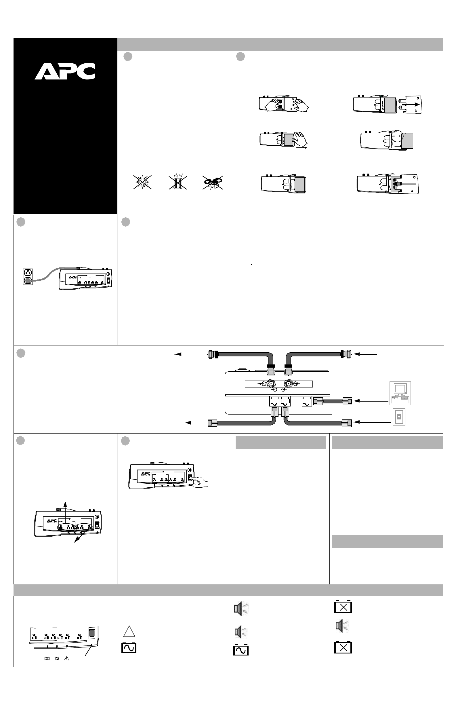
Connect Modem / Phone /
DSL / Fax / 10/100Base-T /
HPNA / Cable Modem / CATV
or DSS to Surge Protection
The Back-UPS protects a single line (2-wire) phone
(including Digital Suscriber Line - DSL), Home
Phoneline Networking Association (HPNA) type
equipment, modem, 10/100Base-T Ethernet, or fax
machines from surges when connected through the
UPS as shown in the drawing on the right.
The UPS also protects a cable modem, CATV
converter, or DSS receiver from surges when it is
connected through the UPS coaxial connectors as
shown in the drawing on the right.
3
I
O
4
When the On Battery indicator is lit, follow this
procedure to shut down the computer, UPS and any
equipment connected to the Battery Power Supplied
outlets:
1. Save any open files and close all applications.
2. Perform an orderly shut down of the operating
system.
3. Switch off all equipment connected to the UPS.
4. Switch Off the UPS to maintain battery capacity.
Note: This procedure needs to be completed before the
battery is fully discharged. Loss of data or corruption of
the operating system is possible if this procedure is not
completed before the battery is fully discharged.
Battery Power Supplied
On Line
The information on the right defines the visual and
associated audible indicators used to determine the
status of the UPS. See the Troubleshooting section for
additional information.
On Line (green)
The UPS is switched On and is supplying
utility power to the Battery Power Supplied
outlets.
Building Wiring Fault (red)
The building wiring is faulty.
On Battery (yellow)
Utility power is outside acceptable limits. The
battery is powering only the Battery Power
Supplied outlets.
Flashing On Battery (yellow)
Continuous Tone - Battery Power
Supplied outlets are overloaded.
Single Beep
- A brief power loss has
occurred (UPS is on battery).
4 Beeps / 30 Seconds - Utility power
is unacceptable. The battery is
supplying power.
Continuous Beeping - Battery
capacity is low. Connected devices
will lose power shortly.
Replace Battery (Red)
See the audible indication below.
Continuous Short Beeps for 1 minute,
repeats every 5 hours. The battery may
need to be replaced.
Flashing Replace Battery (Red)
A UPS internal battery charger fault has
occurred. See the Troubleshooting section.
!
Order Replacement Battery
Replacement batteries can be ordered from local retailers
(a valid credit card may be required), APC or the APC
website (http://www.apc.com). When ordering, please
specify part number RBC21.
Unpack, Inspect, Place or
Mount
1. Unpack and inspect the Back-UPS for damage.
Report any damage to APC Customer Service.
2. Inspect the contents of the box for the following
items:
• Back-UPS VS 500
• Software CD-ROM
• USB Cable (RJ-45 to USB)
• Telephone Cable (with RJ-11 connectors)
• This manual.
• Warranty Registration Card
3. Place the UPS to avoid:
• Direct sunlight
• Excessive heat
• Excessive humidity or contact with fluids
• Excessive dust.
4. Mount the UPS on a wall (optional) or other sur-
face as defined in Wall Mounting of UPS on the
back page.
1
The Self Test is designed to determine:
• If the battery is healthy or if it needs to be
replaced.
• If the Battery Power Supplied outlets are
overloaded.
The Self Test can be initiated at any time and is
performed automatically every two weeks of
continuous operation. A Self Test should be
performed whenever a device is first connected
to a Battery Power Supplied Outlet, to confirm
that a new device will not overload the UPS.
Procedure:
1. Perform steps 1 and 2 of the Manual
Computer Shutdown procedure. Do not
switch Off the computer or any connected
device.
2. Switch the UPS Off and then On.
3. Watch the visual indicators and listen for
any audible indicators during the test, to
note possible fault indications.
See the Indicators section for an
explanation of all visual and audible
indications associated with the operation of
the UPS.
Self Test
Connect other Equipment
to the UPS
Battery Power Supplied Outlets
These three outlets are powered whenever the UPS is
switched On. During power outage or other utility
problems (brownouts, over-voltages), these outlets
will be powered for a limited time by the battery in
the UPS. Plug a PC, monitor, and one other data-
sensitive device (Zip drive or modem for example)
into these outlets.
6
Full-Time Surge Protection Outlets
All outlets provide surge protection. These 3 outlets
are powered whenever utility power is available -
regardless of whether the UPS power switch is On or
Off. Plug a printer, fax machine, scanner or other
peripherals that do not need battery power
during an outage, into these outlets.
Manual Computer Shutdown
Indicators
Connect USB Cable and
Install Software (optional)
Note: The Back-UPS software CD-ROM provides data
reporting and unattended shutdown of computers
connected to the device. The User’s Guide contains
additional information about the Back-UPS software. The
User’s Guide is contained in the main folder on the
software CD-ROM.
For other Microsoft
®
Windows or Macintosh
®
operating
systems, please follow the steps below, as appropriate:
Windows
®
98 and Windows
®
Me Users
Please insert the APC PowerChute Personal Edition
Software CD-ROM included with your Back-UPS into the
CD-ROM drive of your computer. The installation
program will load automatically. Please follow the on-
screen instructions to install the software.
Windows
®
2000 Users
The APC PowerChute Personal Edition Software CD-
ROM included with your UPS contains a “wizard” that
optimizes your system’s power settings for operation with
your Back-UPS. It does this by changing various settings
in Power Options Properties in the Control Panel.
5
CABLE OUT CABLE IN
DSL / MODEM / NETWORK WALL OUTLET DATA PORT
OUT TO
CABLE MODEM,
CATV CONVERTER,
INTERNET SERVICE
PROVIDER (ISP),
CATV, or DSS
TO COMPUTER
USB PORT
FROM WALL JACK
OUT TO DSL, MODEM,
PHONE, or NETWORK
(HPNA or 10/100BASE-T)
INPUT CABLE
or DSS INPUT
 Loading...