


 Loading...
Interface
Expander
AP9607
®

Thank You!
Thank you for selecting the UPS Interface Expander (AP9607). It has been designed for many years of reliable, maintenance-free service in combination with your American Power Conversion (APC) uninterruptible power supply (UPS). APC is dedicated to the development of high-performance electrical power conversion and control products. We hope that you will find this product a valuable, convenient addition to your computing system.
Please read this manual! It provides important safety, installation, and operating instructions that will help you get the most from your Interface Expander.
Save this manual! It includes instructions for obtaining warranty service.
Radio frequency interference
WARNING: Changes or modifications to this unit not expressly approved by the party responsible for compliance could void the user’s authority to operate this equipment.
NOTE: This equipment has been tested and found to comply with the limits for a Class B digital device, pursuant to part 15 of the FCC Rules. These limits are designed to provide reasonable protection against harmful interference in a residential installation. This equipment generates, uses and can radiate radio frequency energy and, if not installed and used in accordance with the instructions, may cause harmful interference to radio communications. However, there is no guarantee that interference will not occur in a particular installation. If this equipment does cause harmful interference to radio or television reception, which can be determined by turning the equipment off and on, try to correct the interference by one or more of the following measures:
•Reorient or relocate the receiving antenna.
•Increase the separation between the equipment and receiver.
•Connect the equipment into an outlet on a circuit different from that to which the receiver is connected.
•Consult the dealer or an experienced radio/TV technician for help.
Shielded communications cables must be used with this unit to ensure compliance with the Class B FCC limits.
This Class B digital apparatus complies with Canadian ICES-003.
Cet appareil numérique de la classe B est conforme à la norme NMB-003 du Canada.

Contents
Introduction . . . . . . . . . . . . . . . . . . . . . . . . . . . . . . . . . . . . . . 1
Overview 1
Features of the Interface Expander 2
Hardware and software requirements 3
Choosing cables 4
Safety warning 4
Product Description . . . . . . . . . . . . . . . . . . . . . . . . . . . . . . . . 5
Interface Expander panel 5
Basic monitoring ports 5
Configuration DIP switches 5
Status LED 6
Key Concepts . . . . . . . . . . . . . . . . . . . . . . . . . . . . . . . . . . . . . 7
Simple versus smart signaling 7
Master server versus Interface Expander servers 8
Configuring PowerChute plus for simple signaling 9
Low Battery signal 10
Scheduled shutdowns 10
Setup overview 11
Multiple SmartSlot Installation . . . . . . . . . . . . . . . . . . . . . . . . 12
Introduction 12
Priority of SmartSlot devices 12
If your UPS has one SmartSlot accessory slot 13
Installation in the APC Triple Chassis 13
Installation in the Symmetra PowerArray 14
Daisy chains 14
Installation . . . . . . . . . . . . . . . . . . . . . . . . . . . . . . . . . . . . . . 15
Warning 15
Reminder 15
Installation procedure 15
i

Contents continued
Connecting to Protected Devices . . . . . . . . . . . . . . . . . . . . . . 17
Connection procedure 17
Connecting the Interface Expander 18
Configuring the Interface Expander . . . . . . . . . . . . . . . . . . . 19
Shutdown modes 19
DIP switches 19
Confirmed shutdown mode 20
PowerChute plus support for Confirmed shutdown mode 20
Behavior of Confirmed mode 21
Confirmed shutdown mode and the Advanced port 21 Until Low Battery shutdown mode 22
Timer shutdown mode 22
Testing the Interface Expander 23
Warranty Information . . . . . . . . . . . . . . . . . . . . . . . . . . . . . . 24
Limited warranty 24
Obtaining service 24
Warranty limitations 25
Troubleshooting . . . . . . . . . . . . . . . . . . . . . . . . . . . . . . . . . . 26
If you have problems with your Interface Expander 26
Troubleshooting 26
If problems persist 28
Life-Support Policy . . . . . . . . . . . . . . . . . . . . . . . . . . . . . . . . 29
General policy 29
Examples of life-support devices 29
Specifications . . . . . . . . . . . . . . . . . . . . . . . . . . . . . . . . . . . . 30
Basic port pin assignments 30
Basic port pin assignments 31
Product specifications 32
ii

Introduction
Overview |
The UPS Interface Expander (AP9607) is an American |
|
Power Conversion (APC) SmartSlot™ accessory that pro- |
|
vides two additional computer interface ports for your APC |
|
UPS equipped with a SmartSlot accessory slot. It allows the |
|
UPS to work in conjunction with your power management |
|
software to provide safe system shutdown in extended |
|
power outages for up to three network servers or other |
|
devices. |
|
Since the computer interface port of the UPS remains avail- |
|
able while using the Interface Expander, it is possible to |
|
provide advanced UPS and power management functions to |
|
all protected devices. You can provide power management |
|
with APC PowerChute© plus software and UPS accessories |
|
such as the APC Web/SNMP Management Card (AP9606) |
|
for network connectivity and the Call-UPS© II (AP9208, |
|
AP9608) remote management device. |
|
The Interface Expander draws power from the UPS. It |
|
monitors the UPS and reports power conditions (e.g., On |
|
Battery, Low Battery, On Line) to all attached devices. |
|
|
|
Continued on next page |
1

Introduction continued
Features of
the Interface
Expander
The Interface Expander:
•Mounts in all APC devices equipped with a SmartSlot accessory slot.
•Works well in a heterogeneous network. Servers running different operating systems can monitor the same UPS simultaneously.
•Supports advanced or simple signaling on the advanced port of the UPS.
•Can delay shutdown of the UPS until all servers have shut down gracefully.
•Allows you to restart hung servers.
•Has operating modes that cause the UPS to shut down after confirmation from all protected devices or after an interval set by the user. See “Configuring the Interface Expander” on page 19.
•Does not depend on the operation of the network to protect connected devices. As a hard-wired accessory, the Interface Expander reliably conveys important status messages during poor power conditions.
Continued on next page
2

Introduction continued
Hardware and
software
requirements
The Interface Expander requires:
•An APC device equipped with a SmartSlot accessory slot. SmartSlot devices include—but are not limited to—the APC UPSs in the next item.
•An APC UPS of one the following models:
–Smart- UPS® , except models AP250, AP400, AP600, AP900, AP1250, AP2000, SUVS420, SUVS650, SUVS1000, SUVS1400, SU620.
–Matrix- UPS™ , except models with serial numbers less than x9412.
– Symmetra ™ PowerArray™ .
•APC PowerChute software (simple signaling) or PowerChute plus (advanced or simple signaling) software. See “Simple versus smart signaling: Table 3” on page 7.
•A serial cable (for each connected device) that monitors shutdown signals. See “Choosing cables: Table 1” on page 4.
Continued on next page
3

Introduction |
continued |
|
|
|
|
|
|
Choosing |
This table lists the cables for use with the systems supported |
||
cables: |
by the Interface Expander. When ordering a cable, provide |
||
Table 1 |
the Part Number. |
|
|
|
|
|
|
|
IF you want to |
|
Part |
|
connect the Interface |
THEN order… |
|
|
Number |
||
|
Expander to a(n)… |
|
|
|
|
|
|
|
|
|
|
|
Windows or NetWare |
UPS LAN Manager Cable |
940-0020 |
|
server |
|
|
|
|
|
|
|
UNIX server |
UNIX Basic Signaling |
AP9823 |
|
|
Cable |
|
|
|
|
|
|
IBM AS/400 |
AS/400 Cable Model 9402/ |
940-0006 |
|
|
9404 |
|
|
|
|
|
|
Macintosh Apple- |
PowerChute for Macintosh |
AP9001 |
|
Share server |
(software and cable) |
|
|
|
|
|
|
15-ft extension cable |
UPS Interface Extension |
AP9815 |
|
|
|
|
|
50-ft extension cable |
Isolated Extension Cable |
AP9825 |
|
|
|
|
|
|
|
|
Safety warning The Interface Expander is to be used only in conjunction with an APC UPS. Use only APC UPS monitoring cables. Do not connect a computer to any Interface Expander port using a “straight-through” wired extending cable. Connections using a UPS or cable made by any other manufacturer may cause damage or improper operation of the the Interface Expander unit, the UPS, or the computer.
Do not operate the Interface Expander where the ambient temperature or humidity is outside the limits listed in “Product specifications: Table 7” on page 32.
4
Product Description
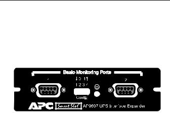
Interface Expander panel: Figure 1
The following figure shows the front panel of the Interface Expander. The panel contains:
•2 Basic monitoring ports
•4 Configuration DIP switches
•a status LED
|
|
|
|
|
|
|
|
|
|
|
|
|
|
|
|
|
|
|
|
Basic |
The two computer interface ports on the Interface Expander |
||
monitoring |
are called Basic ports because they supply simple UPS sig- |
||
ports |
naling for On Battery and Low Battery conditions in the |
||
|
UPS. For further information see “Simple versus smart sig- |
||
|
naling: Table 3,” on page 7. |
||
|
|
|
|
Configuration |
The Interface Expander Configuration DIP switches control |
||
DIP switches |
the shutdown operation of the unit. See “Configuring the |
||
|
Interface Expander” on page 19. |
||
|
|
|
|
|
|
|
Continued on next page |
5

Product Description continued
Status LED: The Interface Expander status LED provides important Table 2 information concerning operation of the unit. Refer to the
table below for a description of the conditions indicated by the LED.
Status |
Description |
|
|
On |
Normal operation. The Interface |
|
Expander is on and communicating |
|
with the UPS. |
|
|
Mostly on, with a single |
The Interface Expander is signaling a |
blink off |
UPS On Battery condition to the con- |
|
nected servers. |
|
|
Mostly on, with two |
The Interface Expander is signaling |
blinks off |
On Battery and Low Battery condi- |
|
tions to the connected servers, and will |
|
eventually shut down the UPS. |
|
|
Flashing continuously |
Shutdown of the UPS is imminent. |
|
|
Mostly off, with a single |
UPS outputs are off— UPS is in Sleep |
flash on |
mode. |
|
|
Blinking slowly and |
The Interface Expander failed its self- |
continuously |
test. |
|
|
Off |
The Interface Expander is powered off |
|
or is not able to communicate with the |
|
UPS. |
|
|
|
|
6
Key Concepts
Simple versus The communication between an APC UPS and a connected smart signaling: server can be of two types: simple signaling or smart signal- Table 3 ing. This table provides information that distinguishes the
two types.
|
Communication Types |
||
Item |
|
|
|
Simple Signaling |
Smart Signaling |
||
|
|||
|
|
|
|
UPS mon- |
–On Batter y signal |
–On Batter y signal |
|
itoring |
–Low Batter y signal |
–Low Batter y signal |
|
features |
|
–Continuous advanced |
|
|
|
monitoring visible in |
|
|
|
PowerChute plus |
|
|
|
graphs |
|
|
|
|
|
Software |
PowerChute |
PowerChute plus |
|
used |
(or PowerChute plus |
configured for smart sig- |
|
|
configured for simple |
naling |
|
|
signaling) |
|
|
|
|
|
|
Port type |
Basic |
Advanced or Basic |
|
|
|
|
|
UPS |
–Back-UPS |
–Smart-UPS, |
|
models |
–Smart-UPS † |
–Matrix-UPS, and |
|
supported |
–Matrix-UPS |
–S ymmetra PowerArray |
|
|
–S ymmetra PowerArray |
|
|
|
|
|
|
Communi- |
Cables in the interface |
Cable supplied with |
|
cation |
kit associated with each |
PowerChute plus |
|
cables |
OS. See “Choosin g |
|
|
|
cables: Table 1” on page |
|
|
|
4. |
|
|
|
|
|
|
†See “Hardware and software requirements,” on pa ge 3 for a listing of APC UPSs that do not support simple signaling with the Interface Expander.
Continued on next page
7

Key Concepts continued
Master server |
A “master” server is a server connected to the (Advanced) |
versus Interface |
computer interface port of the UPS. This server uses |
Expander |
PowerChute plus, configured for smart signaling, to moni- |
servers |
tor and control the UPS. Although the Advanced port on the |
|
UPS can provide simple signaling, we strongly recommend |
|
using it for smart signaling with the advanced capabilities of |
|
PowerChute plus. |
|
Servers connected to the Basic ports of the Interface |
|
Expander use simple signaling with PowerChute or |
|
PowerChute plus to provide UPS shutdown capabilities and |
|
advanced notification features. If you are running |
|
PowerChute plus on these servers, you must configure it for |
|
simple signaling. See “Configuring PowerChute plus for |
|
simple signaling” on page 9. |
|
|
|
Continued on next page |
8

Key Concepts continued
Configuring |
To use PowerChute plus on a server connected to the Inter- |
|
PowerChute plus face Expander, configure PowerChute plus for simple |
||
for simple |
signaling. Use either one of these procedures. |
|
signaling |
1 |
(Re)install PowerChute plus. When the installation |
|
|
program prompts for the UPS Type, select “Back- |
|
|
UPS” and continue with the installation, including |
|
|
a reboot of the system. |
|
2 |
Run PowerChute plus and connect to the UPS. |
|
3 |
Verify that the status line on the PowerChute plus |
|
|
screen shows “On Line.” Proceed with Step 4 |
|
|
below. |
|
|
OR |
|
1 |
With PowerChute plus running, select Communi- |
|
|
cation Parameters from the Configuration |
|
|
menu. |
|
2 |
Click Simple Signalling. Click OK. |
|
3 |
Close PowerChute plus. |
|
4 |
If the UPS had previously been connected using |
|
|
smart signaling: |
|
|
a Unplug the UPS. |
|
|
b Turn off the UPS output by pressing the Off |
|
|
button for at least 5 seconds. |
|
|
c Change communication cables, using the sim- |
|
|
ple signaling cable from the interface kit. (See |
|
|
“Choosing cables: Table 1” on page 4.) |
|
5 |
Restart PowerChute plus and attach the server to |
|
|
the UPS. |
|
6 |
Verify that the status of the UPS on the |
|
|
PowerChute plus screen shows “On Line.” |
Continued on next page
9
Loading...