


 Loading...
Installation and Start-Up
InfraStruXure®
For Medium Data Centers
40 kW 208/480/600 V

About this Manual
This manual covers basic installation and start-up procedures for certified electricians, American Power Conversion (APC®) Field Service Engineers, or APC-trained installers of a 40 kW InfraStruXure® system.
For information about installing specific components in your InfraStruXure system, see the documentation included with each component. Before installing or operating any component, refer to the safety instructions in the component’s manual or safety sheet.
Note: The illustrations of products in this manual may vary slightly from the products in your InfraStruXure system.
InfraStruXure System - Installation and Start-Up

Contents
Safety................................................................................ |
1 |
IMPORTANT SAFETY INSTRUCTIONS
- SAVE THESE INSTRUCTIONS . . . . . . . . . . . . . . . . . . . . . . . . . . . . . .1
Symbols used in this manual . . . . . . . . . . . . . . . . . . . . . . . . 1
Warnings . . . . . . . . . . . . . . . . . . . . . . . . . . . . . . . . . . . . . . . . . . . . . . . .2
Installation/Maintenance . . . . . . . . . . . . . . . . . . . . . . . . . . . |
2 |
Maintenance performed while the PDU is receiving input power . 2 |
|
Total Power Off . . . . . . . . . . . . . . . . . . . . . . . . . . . . . . . . . |
3 |
DANGER—Risk of Electric Shock! . . . . . . . . . . . . . . . . . . . . |
4 |
Emergency Power Off (EPO) . . . . . . . . . . . . . . . . . . . . . . . . |
4 |
EMI . . . . . . . . . . . . . . . . . . . . . . . . . . . . . . . . . . . . . . . . . |
4 |
Site Planning.................................................................... |
5 |
Space Considerations. . . . . . . . . . . . . . . . . . . . . . . . . . . . . |
. . . . . . . . .5 |
Installation Procedures................................................... |
7 |
Installation Procedure Overview . . . . . . . . . . . . . . . . . . . . . . . . . . . . .7
Tools Required . . . . . . . . . . . . . . . . . . . . . . . . . . . . . . . . . 9
Level the PDU, UPS, NetShelter, and XR Battery Enclosures. . . . .10 Exchange Side Panels . . . . . . . . . . . . . . . . . . . . . . . . . . . . . . . . . . . .11
Exchange Side Panels . . . . . . . . . . . . . . . . . . . . . . . . . . . 11
Connect Battery Enclosure communication cables . . . . . . . . |
12 |
Join the PDU, UPS, and XR Battery Enclosures. . . . . . . . . . . . . . . .13 Connect Utility Conductors to the PDU. . . . . . . . . . . . . . . . . . . . . . .14
Access the PDU Main Input switch . . . . . . . . . . . . . . . . . . . 14
Attach conduit to the PDU for the input conductors . . . . . . . . 14
Install a circuit breaker . . . . . . . . . . . . . . . . . . . . . . . . . . . 15
Route the input conductors to the Main Input switch . . . . . . . 16
Connect input conductors . . . . . . . . . . . . . . . . . . . . . . . . . 16
Connect AC Power and Control Wiring. . . . . . . . . . . . . . . . . . . . . . .18
InfraStruXure System - Installation and Start-Up |
i |
Connect DC Power Wiring, if Applicable . . . . . . . . . . . . . . . . . . . . . 20
Cascade XR Battery Enclosures . . . . . . . . . . . . . . . . . . . . . 20
Connect power cables from the XR Battery Enclosure to the
Symmetra PX UPS . . . . . . . . . . . . . . . . . . . . . . . . . . . . . . 21
Connect an Emergency Power Off Switch . . . . . . . . . . . . . . . . . . . . 22
Overview . . . . . . . . . . . . . . . . . . . . . . . . . . . . . . . . . . . . |
22 |
Connect an EPO switch to the user connection plate . . . . . . . 23
Connect User Input Contacts and Relay Outputs to the
User Connection Plate . . . . . . . . . . . . . . . . . . . . . . . . . . . . . . . . . . . . 24
Overview . . . . . . . . . . . . . . . . . . . . . . . . . . . . . . . . . . . |
24 |
Route and Attach Power Cables to the Racks. . . . . . . . |
. . . . . . . . . 25 |
Overhead Wiring . . . . . . . . . . . . . . . . . . . . . . . . . . . . . . . |
25 |
Under Floor Wiring . . . . . . . . . . . . . . . . . . . . . . . . . . . . . |
26 |
Route Data Cables to the InfraStruXure Manager Hub (or Switch) 28 |
|
Start-Up Procedure........................................................ |
29 |
Apply power to the system . . . . . . . . . . . . . . . . . . . . . . . . . . . . . . . . 29
Safety warnings . . . . . . . . . . . . . . . . . . . . . . . . . . . . . . . 29
Verify UPS battery operation . . . . . . . . . . . . . . . . . . . . . . . 32
Verify proper voltage and phase rotation at the UPS . . . . . . . 34
Start the UPS . . . . . . . . . . . . . . . . . . . . . . . . . . . . . . . . . 34
Verify bypass operation . . . . . . . . . . . . . . . . . . . . . . . . . . 36
Power the PDU Distribution Breakers . . . . . . . . . . . . . . . . . 38
Configure the InfraStruXure Manager . . . . . . . . . . . . . . . . . 39
Specifications ................................................................ |
41 |
40 kW InfraStruXure PDU. . . . . . . . . . . . . . . . . . . . . . . . . . . . . . . . . . 41
ii |
InfraStruXure System - Installation and Start-Up |
Safety
IMPORTANT SAFETY INSTRUCTIONS - SAVE THESE INSTRUCTIONS
This manual contains important instructions that must be followed during installation, operation, and maintenance of the InfraStruXure System.
Symbols used in this manual
Electrical Hazard: Indicates an electrical hazard which, if not avoided, could result in injury or death.
Danger: Indicates a hazard which, if not avoided, could result in severe personal injury or death.
Warning: Indicates a hazard which, if not avoided, could result in personal injury or damage to product or other property.
Heavy: Indicates a heavy load that should not be lifted without assistance.
Caution: Indicates a potential hazard which, if not avoided, could result in damage to the equipment or other property.
Tip Hazard: This equipment is easily tipped. Use extreme caution when unpacking or moving.
Note: Indicates important information.
Indicates that more information is available on the same subject.
InfraStruXure System - Installation and Start-Up |
1 |

Warnings
Installation/Maintenance
Only a certified electrician can perform these tasks:
•Connect the Power Distribution Unit (PDU) to utility power
•Install an upstream circuit breaker
•Route and connect the power cables for under-floor wiring
•Connect a switch to the Emergency Power Off (EPO) interface on the PDU Only a certified electrician or an APC Field Service Engineer can perform these tasks:
•Connect the PDU to the Symmetra PX UPS
•Perform maintenance of the PDU
Install a circuit breaker to protect the PDU against over-current when you connect the PDU to utility power.
See “Specifications” on page 41 to determine the type of circuit breaker to install.
Maintenance performed while the PDU is receiving input power
APC does not recommend that you perform maintenance of the PDU while it is receiving input power. However, due to the critical nature of data center loads, this may occur. If you must perform maintenance while the PDU is receiving input power, observe the following precautions to reduce the risk of electric shock:
1.Never work alone.
2.Perform the maintenance only if you are a certified electrician who is trained in the hazards of live electrical installation.
3.Know the procedure for disconnecting electricity to the PDU and the data center in case of an emergency.
4.Wear appropriate personal protective equipment.
5.Use double-insulated tools.
6.Always follow local and site regulations when working on the PDU.
2 |
InfraStruXure System - Installation and Start-Up |
Safety: Warnings
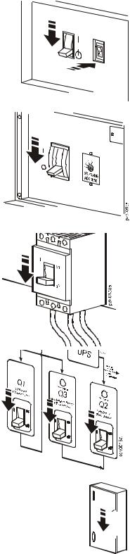
Total Power Off
Set the UPS DC Disconnect circuit breaker and System Enable switch to OFF.
px0003a
If applicable, set the XR Battery Enclosure DC Disconnect circuit breaker to OFF.
Set the PDU Main Input circuit breaker (or switch) to OFF.
Open (turn OFF) the Q1, Q2, and Q3 circuit breakers on the PDU.
Set the upstream input utility circuit breaker to the OFF or Locked Out position.
 gen0137a
InfraStruXure System - Installation and Start-Up |
3 |

Safety: Warnings
DANGER—Risk of Electric Shock!
Electrical Hazard: Hazardous, live parts inside the Symmetra PX UPS are energized from the battery supply even when the AC power is disconnected.
Hazardous, live parts may exist inside the InfraStruXure PDU because of the Symmetra PX UPS inverter even when the AC power is disconnected. Test any electrical parts before touching them.
Emergency Power Off (EPO)
Hazardous voltage from the branch circuit must be isolated from the 24VAC, 24VDC, and contact closure. 24VAC and 24VDC are considered Class 2 circuits as defined in Article 725 of the National Electrical Code (NFPA 70) and Section 16 of the Canadian Electrical Code (C22.1).
A Class 2 circuit is a source having limited voltage and energy capacity as follows:
a.If an Inherently Limited Power Source, voltage and energy are limited to less than 30VAC, less than 30VDC, and 8A.
b.If not an Inherently Limited Power Source, voltage and energy are limited to less than 30VAC, less than 60VDC, 250VA, and the current is limited to 1000/Vmax. The fuse is limited to 5A if less than 20VAC or 20VDC, or 100/Vmaximum if less than 30VAC or 60VDC.
If you choose to use a 24VAC, 24VDC, or contact closure connection to the EPO, use one of the following UL-listed wire types:
•CL2 Class 2 cable for general purpose use
•CL2P Plenum cable for use in ducts, plenums, and other space used for environmental air
•CL2R Riser cable for use in a vertical run shaft from floor to floor
•CL2X Limited Use cable for use in dwellings and for use in a raceway
•For installation in Canada, the cable should be CSA Certified, type ELC (extra-low-voltage control cable).
If you do not use a CL2 cable, route the EPO wiring in conduit that does not contain any branch circuit wiring.
EMI
This equipment has been tested and found to comply with the limits for a Class A digital device, pursuant to part 15 of the FCC Rules. These limits are designed to provide reasonable protection against harmful interference when the equipment is operated in a commercial environment. This equipment generates, uses, and can radiate radio frequency energy and, if not installed and used in accordance with this user manual, may cause harmful interference to radio communications. Operation of this equipment in a residential area is likely to cause harmful interference. The user will bear sole responsibility for correcting such interference.
This Class A digital apparatus complies with Canadian ICES-003.
Cet appareil numerique de le class A est conforme a la norme NMB-003 du Canada.
4 |
InfraStruXure System - Installation and Start-Up |
Site Planning
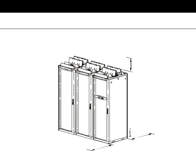
Space Considerations
Use the figure below to determine the space requirements for installing the InfraStruXure PDU, Symmetra PX UPS, and XR Battery Enclosure. Consult local codes and the NEC for additional requirements.
Ceiling Clearance
>304 mm/12 in
Minimum Rear Clearance
208 V: 914 mm/36 in
Minimum Front Clearance |
480 V: 1067 mm/42 in |
208 V 914 mm/36 in
480 V: 1067 mm/42 in
InfraStruXure System - Installation and Start-Up |
5 |
Installation Procedures
Installation Procedure Overview
This section provides the basic steps to install the InfraStruXure power and rack components. Follow the references provided with each step for detailed instructions.
Warning: Do not begin installing your InfraStruXure system without an APC Field Service Engineer present.
Note: Search all boxes and packaging to make sure that they are empty before discarding.
1.Determine the correct placement of the system components by studying the InfraStruXure Configure-To-Order (CTO) report. Move the Symmetra PX UPS, InfraStruXure PDU, XR Battery Enclosure, and NetShelter VX Enclosures to their final location.
Warning: If installing InfraStruXure on a raised floor, make sure that the raised-floor structure has a in2/lb rating that will support the full weight of the InfraStruXure installation. See “Specifications” on page 41.
2.Level the PDU, UPS, NetShelter, and XR Battery Enclosures, using the 13/14-mm wrench included with each unit.
See “Level the PDU, UPS, NetShelter, and XR Battery Enclosures” on page 10 for detailed instructions.
3. Exchange side panels and run battery communication cables, if applicable.
See “Exchange Side Panels” on page 11 for detailed instructions.
4. Join adjacent enclosures.
For instructions on joining the PDU, UPS, and XR Battery Enclosure see “Join the PDU, UPS, and XR Battery Enclosures” on page 13.
For instructions on joining adjacent NetShelter VX Enclosures, see the installation manual included with your enclosures.
5. Ensure total power off.
See “Total Power Off” on page 3 for detailed instructions.
InfraStruXure System - Installation and Start-Up |
7 |

Installation Procedures: Installation Procedure Overview
6. Connect utility conductors to the PDU.
For instructions, see “Connect Utility Conductors to the PDU” on page 14.
7. Connect AC power and control wiring.
See “Connect AC Power and Control Wiring” on page 18 for detailed instructions.
8. Connect DC power wiring, if applicable.
See “Connect DC Power Wiring, if Applicable” on page 20 for detailed instructions.
9 . Connect an EPO switch to the PDU user connection plate
See “Connect an Emergency Power Off Switch” on page 22 for detailed instructions.
10. Connect User Contact Inputs and Relay Outputs to the PDU user connection plate.
See “Connect User Input Contacts and Relay Outputs to the User Connection Plate” on page 24 for detailed instructions.
11. Install Shielding Troughs, Shielding Partitions, and Cable Ladders.
For instructions, see the manuals included with your Shielding Troughs, Shielding Partitions, and Cable Ladders.
12.Install the Rack Automatic Transfer Switches (ATS), Rack Power Distribution Units, and other InfraStruXure rack-mount devices.
For instructions, see the manuals included with your Rack ATS, Rack PDU, or other InfraStruXure rack-mount device.
13. Route and attach power cables to each Rack ATS and/or Rack PDU.
See “Route and Attach Power Cables to the Racks” on page 25 for detailed instructions.
14. Route and attach communication cables to the InfraStruXure Manager hub (or switch).
See “Route Data Cables to the InfraStruXure Manager Hub (or Switch)” on page 28 for detailed instructions.
15.Start the system.
Only qualified, APC-trained personnel may perform a system start-up.
See “Start-Up Procedure” on page 29 for detailed instructions.
8 |
InfraStruXure System - Installation and Start-Up |

Installation Procedures: Installation Procedure Overview
16. Configure the InfraStruXure Manager.
For instructions, see the manual included with your InfraStruXure Manager.
Tools Required
The following tools are required to perform the procedures in this manual. Additional tools may be required for components not covered in this manual.
Tool |
Supplied? |
13-mm socket wrench |
No |
17-mm socket wrench |
No |
T-20 screwdriver |
No |
Standard screwdriver |
No |
Level |
No |
Open-ended wrench (14 mm) for adjusting the leveling feet |
Yes |
Step ladder |
No |
Crimper |
No |
Volt-meter |
No |
Phase-rotation meter |
No |
InfraStruXure System - Installation and Start-Up |
9 |
Level the PDU, UPS, NetShelter, and XR
Battery Enclosures
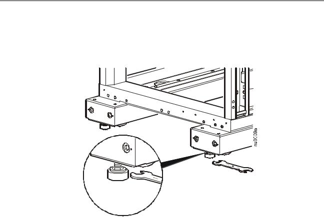
Leveling feet are attached under the enclosure at each corner. The leveling feet can help provide a stable base if the selected floor space is uneven, but they are not intended to compensate for a badly sloped surface. To level the enclosure:
1.Use a 14-mm end of the open-ended wrench (provided) to extend the leveling foot until it makes firm contact with the floor.
2.Repeat step 1 for each of the remaining leveling feet.
3.Use a level to determine which feet need further adjustment to level the enclosure. Adjust as necessary.
10 |
InfraStruXure System - Installation and Start-Up |
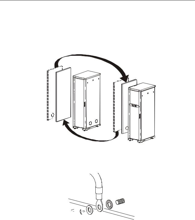
Exchange Side Panels
Before installing the InfraStruXure PDU, Symmetra PX UPS, and XR Battery Enclosure, exchange side panels so that the adjacent panels will have matching holes for joining the enclosures together and for routing input and output wiring between them. The following side panels will need to be exchanged:
•Adjacent side panels of a PDU and UPS
•Adjacent side panels of a XR Battery Enclosure and a UPS
•Adjacent side panels of two XR Battery Enclosures
 psx0136a
Exchange Side Panels
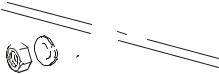
1. Detach the ground wires from the side panels.
 gen0303a
2.Remove the solid side panels from the side of the UPS that will be adjacent to the PDU and the XR Battery Enclosure in the planned configuration.
InfraStruXure System - Installation and Start-Up |
11 |
Loading...