


 Loading...
User Manual Back-UPS™
BE425M/425M-LM, BN450M/450M-CA
Safety and General Information
Inspect the package contents upon receipt. Notify the carrier and dealer if there is any damage.
SAVE THESE INSTRUCTIONS - This section contains important instructions that should be followed during installation and maintenance of the UPS and batteries.
 DANGER
HAZARD OF ELECTRIC SHOCK, EXPLOSION, OR ARC FLASH
•This UPS is intended for indoor use only.
•Do not operate this UPS in direct sunlight, in contact with fluids, or where there is excessive dust or humidity.
•Connect the UPS power cable directly to a wall outlet.
•Be sure the air vents on the UPS are not blocked. Allow adequate space for proper ventilation.
Failure to follow these instructions will result in death or serious injury.
Inventory
|
2a |
46 |
|
bu |
|

Connect the Battery
The Back-UPS is shipped with one battery cable disconnected.
|
2a |
46 |
|
bu |
|
|
3a |
46 |
|
bu |
|
Remove the “Stop! Connect the Battery” label that covers the outlets.
The battery connector is located on the underside of the unit.
|
4a |
46 |
|
bu |
|
|
5a |
46 |
|
bu |
|
Slide the battery connector handle away from its disconnected position.
Turn the battery connector to a 90-degree upright position and push it into the unit.
Specifications
Model |
|
BE425M / BE425M-LM |
|
BN450M / BN450M-CA |
Input |
Voltage |
120 Vac |
Nominal |
|
|
Frequency |
50/60 Hz + 1Hz auto-sensing |
||
|
Brownout Transfers |
92 Vac Typical |
||
|
Over-voltage Transfer |
139 Vac Typical |
||
Output |
UPS Capacity |
425 VA, 255 W |
|
450 VA, 255 W |
|
No. of Outlets |
6 |
|
|
|
Battery Backup/Surge Outlets |
4 / 2 |
||
|
Total output current |
6A |
|
|
|
Voltage - On Battery |
115 Vac ± 8% |
||
|
Frequency - On Battery |
50/60 Hz + 1 Hz |
||
|
Transfer Time |
4 ms Typical |
||
Protection |
EMI/RFI Filter |
Full time |
||
and |
AC Input |
Resettable circuit breaker |
||
Filtering |
|
|
|
|
Battery |
Type |
Sealed, maintenance-free, lead acid, 12V |
||
|
Average Life |
3 - 5 years, the number of discharge cycles, poor |
||
|
|
quality AC power, environmental temperature and |
||
|
|
humidity may shorten the battery lifetime |
||
|
Charging Time |
8 hours |
||
|
|
|
|
|
2 |
Back-UPS BE425M/425M-LM, BN450M/450M-CA |
Model |
BE425M / BE425M-LM |
BN450M / BN450M-CA |
|
Physical |
Net Weight |
5.7 lb (2.6 kg) |
|
|
Dimensions |
9.98 in x 4.13 in x 5.51 in |
|
|
LxWxH |
25.35 cm x 10.5 cm x 14.02 cm |
|
|
Operating Temperature |
32º F to 104º F (0º C to 40º C) |
|
|
Storage Temperature |
-4º F to 122º F (–20º C to 50º C) |
|
|
Operating Relative Humidity |
0 to 95% non-condensing humidity |
|
|
Operating Elevation |
0 to 10,000 ft (0 to 3000 m) |
|
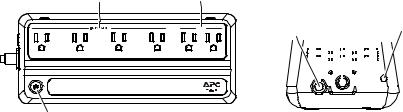
Connect Equipment
Battery Backup + Surge |
Surge Protection |
Protection Outlets |
Outlets |
|
Surge |
Back-UPS 450 |
|
|
|
|
|
|
|
|
|
|
|
|
Building |
|
Circuit |
AC Power |
|
Wiring |
||||||||||
|
Fault |
||||||||||||
Breaker |
|
|
Inlet |
|
|||||||||
|
|
|
|
|
|||||||||
|
|
|
|
|
|
|
|
|
|
|
|
|
|
|
|
|
|
|
|
|
|
|
|
|
|
|
|
|
|
|
|
|
|
|
|
|
|
|
|
|
|
|
|
|
|
|
|
|
|
|
|
|
|
|
|
|
|
|
|
|
|
|
|
|
|
|
|
|
|
|
|
|
|
|
|
|
|
|
|
|
|
|
|
|
|
|
|
|
|
|
|
|
|
|
|
|
|
|
|
|
|
|
|
|
|
|
|
|
|
|
|
POWER |
bu461a |
bu460a |
|
||
|
|
|
Button |
|
|
Feature |
Function |
Suggested Use |
Battery Backup + |
• Receive power from the battery for a |
Connect a computer, monitor |
Surge Protection |
limited period of time when a power |
and other critical peripheral |
Outlets |
outage, or brownout condition |
devices that need to remain on |
|
occurs. |
during power outages or AC |
|
• Provide protection from power |
problems. |
|
surges or spikes. |
|
Surge Protection |
• Provide protection from power |
Connect non-critical |
Outlets |
surges or spikes. |
peripheral devices (such as |
|
|
printer, scanner, etc.) that do |
|
|
not need to remain on during |
|
|
power outages or AC |
|
|
problems. |
|
|
|
Turn On the Back-UPS
Press the POWER button. It will illuminate green and a single short beep indicating that the Back-UPS is on and providing protection for connected equipment.
The Back-UPS battery will charge regardless of whether the Back-UPS is switched on or off as long as it is connected to AC power. The UPS will have full runtime capability after the initial 24-hour charging period, connected to AC power.
If the red Building Wiring Fault indicator (located on the end near the power cord) is lit, your building wiring may present a shock hazard that should be corrected by a qualified electrician.
Back-UPS BE425M/425M-LM, BN450M/450M-CA |
3 |
Turn Off the Back-UPS
Press the POWER button for at least 2 seconds. At the first beep, release the button and the UPS will turn off. A 2 second delay has been added to mitigate unintentional contact with the POWER button.
Quick Mute
The Back-UPS is able to temporarily mute user correctable alarms such as On Battery.
During such alarms, a short press (less than 2 seconds) of the POWER button will temporarily mute the alarm until the condition has been reset. A short double beep will confirm that Quick Mute has been activated. Pressing the POWER button for more than 2 seconds will turn off the UPS.
Other critical events such as Battery replacement and Charger notification can not be temporarily muted. The unit in these cases must be turned off.
On Battery Indicator Modes
With the UPS turned on, configuring the On Battery Indicator modes below is done by holding down the POWER button and waiting for the third beep. At the third beep, the POWER button will cycle red / green. Release the POWER button and its color will indicate the mode the UPS is in. Press the POWER button to cycle through each mode. See the following table for the 3 mode selection colors. Once the mode has been selected, wait 5 seconds and the setting will be committed to the UPS.
Mode |
Visual |
Audible Indicator |
Mode Selection |
|
Indicator |
Color |
|||
|
|
|||
Quiet Alarm |
The POWER |
No alarm until Low Battery |
Flashing green |
|
(default) |
button is solid |
notification where the alarm beeps |
||
|
green and |
twice every 30 seconds |
|
|
|
flashes twice |
|
|
|
No Alarm |
No alarm while the UPS is On |
|
||
every 2 seconds |
Flashing red |
|||
|
until Low |
Battery |
|
|
|
Battery |
|
|
|
Full Alarm |
Alarm sounds 4 beeps every 30 |
|
||
notification |
|
|||
|
seconds until Low Battery |
|
||
|
where it will |
|
||
|
notification where the alarm beeps |
Flashing amber |
||
|
flash green in |
|||
|
every half second. As the UPS shuts |
|||
|
rapid |
down, it sounds one beep every 4 |
|
|
|
succession. |
|
||
|
seconds |
|
||
|
|
|
||
|
|
|
|
Voltage Sensitivity Adjustment (optional)
The Back-UPS detects and reacts to line voltage distortions by transferring to battery backup power to protect connected equipment. In situations where either the Back-UPS or the connected equipment is too sensitive for the input voltage level it is necessary to adjust the transfer voltage.
1.Turn off the UPS while connected to a wall outlet.
2.Press and hold the ON/OFF button for 10 seconds. The POWER button will alternate greenred to indicate that the Back-UPS is in Program mode.
3.The POWER button will flash either green, amber, or red to indicate the current sensitivity level. Refer to the table for an explanation of the transfer voltage sensitivity levels.
4.To exit Program mode wait five seconds and all LED indicators will extinguish. Program mode is no longer active.
4 |
Back-UPS BE425M/425M-LM, BN450M/450M-CA |
Loading...