


PowerView™
Model AP9215
User’s
Manual

Thank You !
Thank you for selecting the American Power Conversion PowerView. It has been designed for many years of reliable, maintenance-free service in combination with your American Power Conversion Uninterruptible Power Source. American Power Conversion is dedicated to the development of high-performance electrical power conversion and control products and we hope that you will find this product a valuable, convenient addition to your computing system.
Please read this manual! It provides important installation and operating instructions that will help you get the most from your PowerView.
Save this manual! It includes instructions for obtaining factory service should the proper operation of the accessory come into question..

Contents |
|
Introduction ............................................................. |
2 |
Supported UPS Models ...................................................... |
2 |
Controls and Indicators ..................................................... |
3 |
Installation ............................................................... |
4 |
General Navigation .................................................. |
5 |
Menu Structure ......................................................... |
6 |
Control .............................................................................. |
7 |
Status ................................................................................ |
8 |
Setup ................................................................................. |
9 |
Accessories ..................................................................... |
11 |
Logging .......................................................................... |
12 |
PowerView Information and Configuration .................... |
13 |
Diagnostics ..................................................................... |
14 |
Help ............................................................................... |
14 |
Replacing the Language EPROM ............................. |
15 |
Mounting Template ................................................ |
16 |
1
Introduction
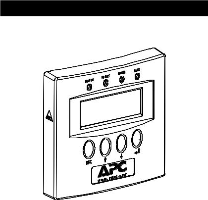
PowerView is a compact control panel and display which provides full control, monitoring and configuration of the connected UPS.
Figure 1 PowerView Front Panel
Supported UPS Models
PowerView supports the following APC UPS model families: Smart-UPS: SU450, SU700, SU1000, SU1400, SU2200, SU3000 Matrix-UPS: all models
Symmetra: all models
The following APC UPS families are not supported by PowerView: Back-UPS: all models
Smart-UPS: AP250, AP400, AP600, AP900, AP1250, AP2000, SUVS420, SUVS650, SUVS1000, SUVS1400, SU420, SU620
2
Controls and Indicators
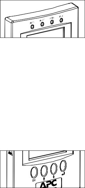
Indicators
Figure 2 Front Panel Indicators
LOAD ON: Indicates that the load connected to the UPS is receiving power (On-line, On-Battery or Bypass).
ON BATT: Indicates that power to the attached load is being supplied by the UPS’s batteries (unavailable while in Bypass).
BYPASS: Indicates that power to the attached load is being supplied through the UPS’s filtering and surge suppression circuits directly. The UPS will not power the load from battery in the event of a power failure. (This feature is available only on Matrix-UPS and Symmetra models).
FAULT: Indicates that the UPS has detected a problem or certain configuration changes (includes both hardware failures and abnormal conditions such as overload or over temperature).
Controls
The control keys are used to navigate between menus, to select menu items, and to input alphanumeric information. The section entitled General Navigation on page 6 provides additional information.
Figure 3 Control Keys
3
Installation
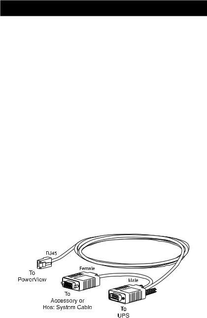
PowerView is connected directly to the UPS through a single interface cable (PN 940-0110) included with the PowerView unit. Follow the steps below to connect PowerView to the UPS:
1.Connect the modular RJ45 plug on the end of the interface cable to the connector at the rear of PowerView.
2.Check the rear of the UPS to determine whether there is a cable already connected to the 9-pin computer interface connector. If there is a cable already connected to this connector, shut down any UPS monitoring software running on the host system, then loosen the thumb screws and remove the existing cable. If there is no cable connected, continue with Step 3.
3.Connect the male end of the 940-0110 cable to the computer interface connector at the rear of the UPS and secure it with the thumbscrews.
4.If it was necessary to remove a cable in Step 2, connect the removed cable to the female connector on the 940-0110 cable and tighten the thumb screws. If no cable was removed, the unused connector may be left unconnected.
PowerView may be mounted to the wall with screws using features on the back or it may be mounted with the supplied hook and loop fasteners. A template for mounting PowerView to the wall is supplied at the end of the manual. PowerView will also sit upright on a flat surface by folding out the wire bail on the rear of the unit.
Figure 4 PowerView Interface Cable
4
 Loading...