


 Loading...
Switched Rack PDU
USER’S GUIDE
®
Contents
Introduction 1
Product Description . . . . . . . . . . . . . . . . . . . . . . . . . . . . . . . . . . 1
Access Procedures. . . . . . . . . . . . . . . . . . . . . . . . . . . . . . . . . . . . 3
How to Recover From a Lost Password . . . . . . . . . . . . . . . . . . . . . 6
Upgrading Firmware through a Serial Connection. . . . . . . . . . . . . . 8
Front Panel . . . . . . . . . . . . . . . . . . . . . . . . . . . . . . . . . . . . . . . 10
Watchdog Features . . . . . . . . . . . . . . . . . . . . . . . . . . . . . . . . . 14
Control Console 15
How to Log On . . . . . . . . . . . . . . . . . . . . . . . . . . . . . . . . . . . . 15
Main Screen . . . . . . . . . . . . . . . . . . . . . . . . . . . . . . . . . . . . . . . 18
Control Console Menus . . . . . . . . . . . . . . . . . . . . . . . . . . . . . . . 21
Web Interface 24
How to Log On . . . . . . . . . . . . . . . . . . . . . . . . . . . . . . . . . . . . 24
Summary Page . . . . . . . . . . . . . . . . . . . . . . . . . . . . . . . . . . . . . 27
Navigation Menu . . . . . . . . . . . . . . . . . . . . . . . . . . . . . . . . . . . 29
Device and Outlet Management Menus 33
How to Configure and Control Outlet Groups. . . . . . . . . . . . . . . . 33
Outlet Settings for Outlets and Outlet Groups . . . . . . . . . . . . . . . 42
Switched Rack PDU Settings. . . . . . . . . . . . . . . . . . . . . . . . . . . . 46
Scheduling Outlet Actions (Web Interface Only) . . . . . . . . . . . . . . 49
Event-Related Menus 53
Introduction. . . . . . . . . . . . . . . . . . . . . . . . . . . . . . . . . . . . . . . 53
Event Log . . . . . . . . . . . . . . . . . . . . . . . . . . . . . . . . . . . . . . . . 55
Event Actions (Web Interface Only). . . . . . . . . . . . . . . . . . . . . . . 60
Event Recipients . . . . . . . . . . . . . . . . . . . . . . . . . . . . . . . . . . . . 63
E-mail Feature . . . . . . . . . . . . . . . . . . . . . . . . . . . . . . . . . . . . . 64
How to Configure Individual Events . . . . . . . . . . . . . . . . . . . . . . 68
I

Switched Rack PDU
USER’S GUIDE
®
Data Menu (Web Interface Only) 69
Log Option . . . . . . . . . . . . . . . . . . . . . . . . . . . . . . . . . . . . . . . 69
Configuration Option . . . . . . . . . . . . . . . . . . . . . . . . . . . . . . . . 70
Network Menu 71
Introduction . . . . . . . . . . . . . . . . . . . . . . . . . . . . . . . . . . . . . . 71
Option Settings . . . . . . . . . . . . . . . . . . . . . . . . . . . . . . . . . . . . 73
System Menu 96
Introduction . . . . . . . . . . . . . . . . . . . . . . . . . . . . . . . . . . . . . . 96
Option Settings . . . . . . . . . . . . . . . . . . . . . . . . . . . . . . . . . . . . 98
Boot Mode 110
Introduction . . . . . . . . . . . . . . . . . . . . . . . . . . . . . . . . . . . . . 110
DHCP Configuration Settings . . . . . . . . . . . . . . . . . . . . . . . . . . 112
Security 117
Security Features . . . . . . . . . . . . . . . . . . . . . . . . . . . . . . . . . . 117
Encryption . . . . . . . . . . . . . . . . . . . . . . . . . . . . . . . . . . . . . . 122
Creating and Installing Digital Certificates . . . . . . . . . . . . . . . . . 126
Firewalls . . . . . . . . . . . . . . . . . . . . . . . . . . . . . . . . . . . . . . . . 133
Using the APC Security Wizard 134 |
|
Overview . . . . . . . . . . . . . . . . . . . . . . . . . . . . . . . . . . . . . . . |
134 |
Create a Root Certificate & Server Certificates . . . . . . . . . . . . . . |
137 |
Create a Server Certificate and Signing Request . . . . . . . . . . . . . |
142 |
Create an SSH Host Key . . . . . . . . . . . . . . . . . . . . . . . . . . . . . |
146 |
APC Device IP Configuration Wizard 148 |
|
Purpose and Requirements . . . . . . . . . . . . . . . . . . . . . . . . . . . 148
Install the Wizard. . . . . . . . . . . . . . . . . . . . . . . . . . . . . . . . . . 149
Use the Wizard . . . . . . . . . . . . . . . . . . . . . . . . . . . . . . . . . . . 150
II

Switched Rack PDU
USER’S GUIDE
®
How to Export Configuration Settings 153
Retrieving and Exporting the .ini File . . . . . . . . . . . . . . . . . . . . 153
The Upload Event and Error Messages . . . . . . . . . . . . . . . . . . . 158
Using the APC Device IP Configuration Wizard. . . . . . . . . . . . . . 160
File Transfers 161 |
|
Introduction . . . . . . . . . . . . . . . . . . . . . . . . . . . . . . . . . . . . . |
161 |
Upgrading Firmware: Methods and Tools . . . . . . . . . . . . . . . . . |
162 |
Verifying Upgrades and Updates . . . . . . . . . . . . . . . . . . . . . . . |
170 |
Product Information 171 |
|
Warranty and Service . . . . . . . . . . . . . . . . . . . . . . . . . . . . . . . 171
Life-Support Policy . . . . . . . . . . . . . . . . . . . . . . . . . . . . . . . . . 173
Index 174
III

Switched Rack PDU
USER’S GUIDE
®
Introduction
Product Description
Features of the Switched Rack PDU
The APC® Switched Rack Power Distribution Unit (PDU) is a stand-alone, network-manageable device that provides current monitoring and allows programmable control of eight, sixteen, or twenty-four power outlets (depending on the model).
You can manage a Switched Rack PDU through its Web interface, its control console, the InfraStruXure® Manager, or SNMP:
•The Web interface supports using HTTPS access with Secure Sockets Layer (SSL) and using HTTP access.
•You can access the control console through a serial connection, Telnet, or Secure SHell (SSH).
•Your Rack PDU is compatible with the APC InfraStruXure system and can be monitored and managed through the InfraStruXure Manager.
•You can use an SNMP browser and the APC PowerNet® Management Information Base (MIB) to manage your Rack PDU.
Switched Rack PDUs have these additional features:
•Current monitoring per phase or bank
•Configurable alarm thresholds that provide network and visual alarms to help avoid overloaded circuits
•Independent outlet control
•Configurable power delays
•24 independent outlet user accounts
1

Switched Rack PDU
USER’S GUIDE
®
•Four levels of user access accounts—Administrator, Device Manager, Read Only User, and Outlet User
•Event and data logging—the event log is accessible by Telnet, Secure CoPy (SCP), File Transfer Protocol (FTP), serial connection, or Web browser (using HTTPS access with SSL, or using HTTP access). The data log is accessible by Web Browser, SCP, and FTP
•E-mail notifications for Rack PDU and system events
•SNMP traps, Syslog messages, and e-mail notifications based on the severity level of Rack PDU and system events
•A selection of security protocols for authentication and encryption
The Rack PDU does not provide power protection. Therefore, APC does not recommend plugging a unit directly into any unprotected power source, such as a wall outlet.
Initial setup
You must define the following three TCP/IP settings for the Switched Rack PDU before it can operate on the network:
•IP address of the Rack PDU
•Subnet mask
•IP address of the default gateway
To configure the TCP/IP settings, see the Installation and Quick Start manual provided as a PDF file on the Utility CD that came
See also with your Rack PDU and as a printed manual.
2

Switched Rack PDU
USER’S GUIDE
®
Access Procedures
Overview
The Switched Rack PDU has two internal interfaces (control console and Web interface) that allow you to manage the Rack PDU.
For more information about the internal user interfaces, see Control Console and Web Interface.
The SNMP interface also allows you to use an SNMP browser with the PowerNet® Management Information Base (MIB) to manage the Rack PDU.
To use the PowerNet MIB with an SNMP browser, see the
PowerNet® SNMP Management Information Base (MIB)
Reference Guide (\doc\en\mibguide.pdf), which is provided on the See also Utility CD that came with your Switched Rack PDU.
Access priority for logging on
Only one user at a time can log on to the Rack PDU to use its internal user interface features. The priority for access is as follows:
•Local access to the control console from a computer with a direct serial connection to the Rack PDU always has the highest priority.
•Telnet or Secure SHell (SSH) access to the control console from a remote computer has priority over Web access.
•Web access, either directly or through the InfraStruXure Manager, has the lowest priority.
3

Switched Rack PDU
USER’S GUIDE
®
Types of user accounts
The Rack PDU has four levels of access (Administrator, Device Manager, Read-Only User, and Outlet User), all of which are protected by password and user name requirements.
•An Administrator can use all of the management menus available in the control console and the Web interface. The Administrator’s default user name and password are both apc.
•A Device Manager can use only the following menus:
–The Device Manager menu and its sub-menus in the control console, and all menus in the top section of the navigation panel of the Web Interface (Switched Rack PDU and Outlets).
–The Log option in the Events menu in the Web interface. A Device Manager can also access the event log in the control console by
pressing CTRL-L.
The Device Manager’s default user name is device; the password is apc.
•An Outlet User can access only the following menus:
–the Control option of the Outlets menu of the Web interface.
–the Device Manager menu and the Phase/Bank Monitor, Outlet Control, and Power Supply Status sub-menus in the control console.
•A Read-Only User has the following restricted access:
–Access through the Web interface only.
–Access to the same menus as a Device Manager, but without the capability to change configurations, control devices, or delete data.
Links to configuration options are visible but are disabled, and the event and data logs display no Delete button.
The Read-Only User’s default user name is readonly, and the default password is apc.
To set User Name and Password values for the four account types, see User Manager and Outlet User Manager.
4

You must use the Web interface to configure values for the Read-Only User, and you must use the control console to configure values for an Outlet User.
Switched Rack PDU
USER’S GUIDE
®
5

Switched Rack PDU
USER’S GUIDE
®
How to Recover From a Lost Password
You can use a local computer, a computer that connects to the Rack PDU or other device through the serial port to access the control console.
1.Select a serial port at the local computer, and disable any service that uses that port.
2.Connect the serial cable (990-0144) to the selected port on the computer and to the configuration port at the Rack PDU:
3.Run a terminal program (such as HyperTerminal®) and configure the selected port as follows:
–9600 bps
–8 data bits
–no parity
–1 stop bit
–no flow control
4.Press ENTER, repeatedly if necessary, to display the User Name prompt. If you are unable to display the User Name prompt, verify the following:
–The serial port is not in use by another application.
–The terminal settings are correct as specified in step 3.
–The correct cable is being used as specified in step 2.
5.Press the Reset button. The Status LED will flash alternately orange and green. Press the Reset button a second time immediately while the LED is flashing to reset the user name and password to their defaults temporarily.
6.Press ENTER as many times as necessary to redisplay the User Name prompt, then use the default, apc, for the user name and password. (If you take longer than 30 seconds to log on after the User Name prompt is redisplayed, you must repeat step 5 and log on again.)
6

7.From the Control Console menu, select System, then User Manager.
8.Select Administrator, and change the User Name and Password settings, both of which are now defined as apc.
9.Press CTRL-C, log off, reconnect any serial cable you disconnected, and restart any service you disabled.
Switched Rack PDU
USER’S GUIDE
®
7
Switched Rack PDU
USER’S GUIDE
®
Upgrading Firmware through a Serial Connection
For a complete description of how to download a firmware upgrade for your Rack PDU, see Upgrading Firmware: Methods and Tools. That section also explains how to use network-based file transfer tools, which complete a firmware upgrade more quickly than the XMODEM protocol described here, which uses a serial connection.
You can use a local computer that connects to the Rack PDU through the serial port on the front panel of the unit.
1.Select a serial port at the local computer, and disable any service which uses that port.
2.Use the supplied serial cable (940-0144) to connect the selected port to the serial port on the front panel of the Rack PDU.
3.Run a terminal program (such as HyperTerminal) and configure the selected port for 9600 bps, 8 data bits, no parity, 1 stop bit, and no flow control. Save the changes.
4.Press ENTER, repeatedly if necessary, to display the User Name prompt.
5.Enter your user name and password (both apc, by default, for administrators only) and press the ENTER key.
6.From the Control Console menu, select, in order, System, Tools, File Transfer, and XMODEM.
7.At the prompt Perform transfer with XMODEM-CRC? type YES, and press ENTER.
8.The system will then prompt you to choose a transfer rate and to change your terminal settings to match the transfer rate. Press ENTER to set the Switched Rack PDU to accept the download.
8

Switched Rack PDU
USER’S GUIDE
®
9.In the terminal program, send the file using the XMODEM protocol. When the transfer finishes, the console will prompt you to restore the baud rate to normal.
Do not interrupt the download.
Caution
The Rack PDU will restart when the download is complete.
Upgrading the firmware will not interfere with the operation of the outlets.
9

Switched Rack PDU
USER’S GUIDE
®
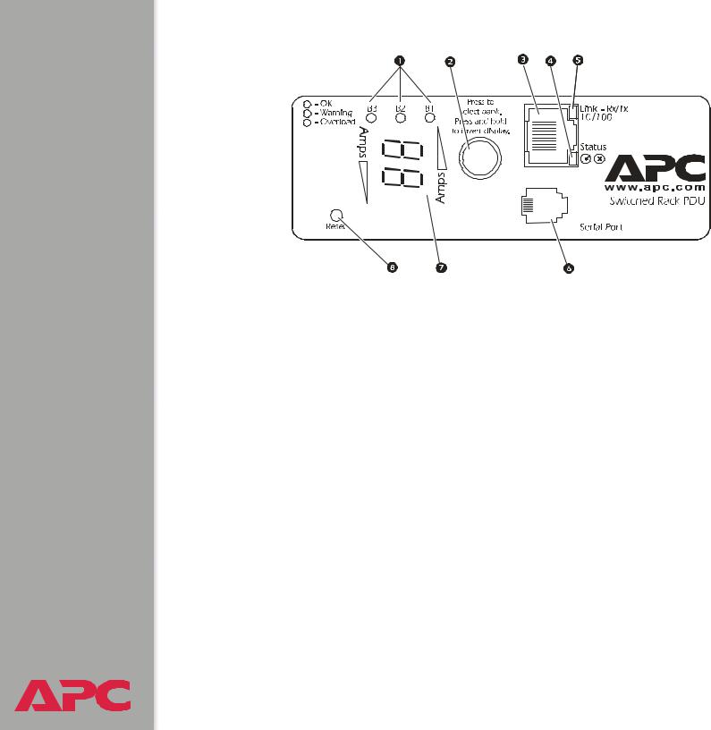
Front Panel
Single-phase
Three-phase
Three-phase Switched Rack PDUs have one of the following two front panels:
10
Switched Rack PDU
USER’S GUIDE
®
|
|
|
|
|
|
|
|
|
|
|
|
|
|
|
|
|
|
|
|
|
|
|
|
Item |
Function |
||||
|
|
|
|
|
|
Load Indicator LED |
Identifies overload and warning conditions for the |
||||
|
|
|
displayed phase or bank. See Load indicator LED. |
||
|
|
|
|
|
|
Input Selector |
On 3-phase models, press the input selector to |
||||
|
|
|
monitor the current of the next phase or bank. |
||
|
|
|
For either 1- or 3-phase units, press and hold the |
||
|
|
|
input selector to display the IP address of the Rack |
||
|
|
|
PDU or to invert the display. At five seconds, the IP |
||
|
|
|
address is displayed; at ten seconds the displayed |
||
|
|
|
numbers invert. |
||
|
|
|
|
|
|
10/100 Base-T Connector |
Connects the Rack PDU to the network. |
||||
Status LED |
See Status LED. |
||||
Link-RX/TX LED |
See Link-RX/TX (10/100) LED. |
||||
RJ-12 Serial Port |
Connects the Rack PDU to a terminal emulator |
||||
|
|
|
program for local access to the control console. |
||
|
|
|
(Use the supplied serial cable 940-0144.) |
||
|
|
|
|
|
|
11

Switched Rack PDU
USER’S GUIDE
®
Item |
Function |
|
|
Digital Display |
Displays the current (amps) for the phase or bank |
|
indicated by the illuminated Load Indicator LED. On |
|
3-phase units, the Digital Display will cycle through |
|
the phases or banks, displaying the current for each |
|
for 3 seconds. |
|
If an internal communication failure or power supply |
|
failure occurs (for either a 1- or 3-phase model), the |
|
Digital Display displays Er, which you can clear by |
|
pressing the input selector. |
|
|
Reset Button |
Resets the Rack PDU without affecting the outlet |
|
status. |
|
|
Link-RX/TX (10/100) LED
This LED indicates the network status.
Condition |
Description |
|
|
Off |
The device that connects the Rack PDU to the network is off or |
|
not operating correctly. |
|
|
Flashing Green |
The Rack PDU is receiving data packets from the network at 10 |
|
Megabits per second (Mbps). |
|
|
Flashing Orange |
The Rack PDU is receiving data packets from the network at |
|
100 Megabits per second (Mbps). |
|
|
Solid Green or |
The Rack PDU is not receiving any network traffic. |
Orange |
|
|
|
12

Switched Rack PDU
USER’S GUIDE
®
Status LED
This LED indicates the network status of the Rack PDU.
Condition |
Description |
|
|
Off |
The Rack PDU has no power. |
|
|
Solid Green |
The Rack PDU has valid TCP/IP settings. |
|
|
Flashing Green |
The Rack PDU does not have valid TCP/IP settings.† |
Solid Orange |
A hardware failure has been detected in the Rack PDU. Contact |
|
APC Worldwide Customer Support. |
|
|
Flashing Orange |
The Rack PDU is making BOOTP requests. |
|
|
Flashing Orange and |
The Rack PDU is making DHCP requests. |
Green (alternating) |
|
|
|
† If you do not use a BOOTP or DHCP server, see the Installation and Quick Start manual provided in PDF on the Utility CD that came with your Rack PDU and as a printed manual to configure the TCP/IP settings.
Load indicator LED
The load indicator LED identifies overload and warning conditions for the displayed phase or bank.
Condition |
Description |
|
|
Solid Green |
The current of the displayed phase or bank is below the |
|
Current Overload threshold. |
|
|
Yellow |
The displayed phase or bank is in a Near Overload Warning |
|
condition. The current is above the Near Overload Warning |
|
threshold. |
|
|
Red |
The displayed phase or bank is in an Overload condition. The |
|
current is above the Overload Alarm threshold. |
|
|
13

Switched Rack PDU
USER’S GUIDE
®
Watchdog Features
Overview
To detect internal problems and recover from unanticipated inputs, the Rack PDU uses internal, system-wide watchdog mechanisms. When it restarts itself to recover from an internal problem, a System: Warmstart event is recorded in the event log.
Network interface watchdog mechanism
The Rack PDU implements internal watchdog mechanisms to protect itself from becoming inaccessible over the network. For example, if the Rack PDU does not receive any network traffic for 9.5 minutes (either direct traffic, such as SNMP, or broadcast traffic, such as an Address Resolution Protocol [ARP] request), it assumes that there is a problem with its network interface and restarts itself.
Resetting the network timer
To ensure that the Rack PDU does not restart if the network is quiet for 9.5 minutes, the Rack PDU attempts to contact the Default Gateway every 4.5 minutes. If the gateway is present, it responds to the Rack PDU, and that response restarts the 9.5-minute timer. If your application does not require or have a gateway, specify the IP address of a computer that is running on the network most of the time and is on the same subnet. The network traffic of that computer will restart the 9.5-minute timer frequently enough to prevent the Rack PDU from restarting.
14
Switched Rack PDU
USER’S GUIDE
®
Control Console
How to Log On
Overview
You can use either a local (serial) connection, or a remote (Telnet or SSH) connection to access the control console.
Use case-sensitive User Name and Password entries to log on (by default, apc and apc for an Administrator, or device and apc for a Device Manager). A Read-Only User has no access to the control console.
If you cannot remember your user name or password, see
How to Recover From a Lost Password.
There is no default password for Outlet User accounts. (An Administrator must define the password and other account characteristics for an Outlet User.)


 See Outlet User Manager.
15

Switched Rack PDU
USER’S GUIDE
®
Remote access to the control console
You can access the control console through Telnet or Secure SHell (SSH), depending on which is enabled. (An Administrator can enable these access methods through the Telnet/SSH option of the Network menu.) By default, Telnet is enabled. Enabling SSH automatically disables Telnet.
Telnet for basic access. Telnet provides the basic security of authentication by user name and password, but not the high-security benefits of encryption. To use Telnet to access the control console from any computer on the same subnet:
1.At a command prompt, type telnet and the System IP address for the Rack PDU (when the PDU uses the default Telnet port of 23), and then press ENTER. For example:
telnet 139.225.6.133
If the PDU uses a non-default port number (between 5000 and 32768), you need to include a colon or a space (depending on your Telnet client) after the IP address and then enter the port number.
2.Enter the user name and password (by default, apc and apc for an Administrator, or device and apc for a Device Manager).
SSH for high-security access. If you use the high security of SSL for the Web interface, use Secure SHell (SSH) for access to the control console. SSH encrypts user names, passwords and transmitted data.
The interface, user accounts, and user access rights are the same whether you access the control console through SSH or Telnet, but to use SSH, you must first configure SSH and have an SSH client program installed on your computer.
16

Switched Rack PDU
USER’S GUIDE
®
Local access to the control console
You can use a local computer that connects to the Rack PDU through the serial port on the front panel of the unit.
1.Select a serial port at the local computer, and disable any service which uses that port.
2.Use the supplied serial cable (940-0144) to connect the selected port to the serial port on the front panel of the Rack PDU.
3.Run a terminal program (such as HyperTerminal) and configure the selected port for 9600 bps, 8 data bits, no parity, 1 stop bit, and no flow control. Save the changes.
4.Press ENTER, repeatedly if necessary, to display the User Name prompt.
17
Switched Rack PDU
USER’S GUIDE
®
Main Screen
Example main screen
The main screen that is displayed when you log on to the control console of a Rack PDU:
User Name : apc |
|
|
|
Password |
: *** |
|
|
American |
Power Conversion |
Network Management Card AOS |
v2.6.4 |
(c) Copyright 2002 All Rights Reserved |
Rack PDU APP |
v2.6.6 |
|
-------------------------------------------------------------------------------
Name |
: MS3 Test |
Unit |
Date : 6/25/2004 |
|
Contact |
: Bill Cooper |
Time |
: 10:16:58 |
|
Location |
: Testing Lab |
User : Administrator |
||
Up Time |
: 0 Days 0 |
Hours 43 Minutes |
Stat |
: P+ N+ A+ |
Switched Rack PDU: Communication Established
------- Control Console -------------------------------------------------------
1- Device Manager
2- Network
3- System
4- Logout
<ESC>- Main Menu, <ENTER>- Refresh, <CTRL-L>- Event Log
18

Switched Rack PDU
USER’S GUIDE
®
Information and status fields
Main screen information fields.
•Two fields identify the APC operating system (AOS) and application (APP) firmware versions. The application firmware uses a name that identifies the type of device that connects to the network. In the Example main screen, the application firmware for the Rack PDU is displayed.
Network Management Card AOS |
v2.6.4 |
Rack PDU APP |
v2.6.6 |
• Three fields identify the system Name, Contact, and Location values.
Name |
: MS3 Test Unit |
Contact |
: Bill Cooper |
Location |
: Testing Lab |
To set the Name, Contact, and Location values, see System Menu.
•An Up Time field reports how long the Rack PDU has been running since it was last reset or since power was applied.
Up Time : 0 Days 0 Hours 43 Minutes
•Two fields identify when you logged on, by Date and Time.
Date : 6/25/2004 Time : 10:16:58
•A User field identifies whether you logged on as Administrator, Device Manager, or Outlet User.
User : Administrator
19

Switched Rack PDU
USER’S GUIDE
®
Main screen status fields.
•A Stat field reports the Rack PDU status.
Stat : P+ N+ A+
P+ |
The APC operating system (AOS) is functioning properly. |
|
|
N+ |
The network is functioning properly. |
|
|
N? |
A BOOTP request cycle is in progress. |
|
|
N– |
The Rack PDU failed to connect to the network. |
|
|
N! |
Another device is using the IP address of the Rack PDU. |
|
|
A+ |
The application is functioning properly. |
|
|
A– |
The application has a bad checksum. |
|
|
A? |
The application is initializing. |
|
|
A! |
The application is not compatible with the AOS. |
|
|
If the AOS status is not P+, contact APC Worldwide Customer Support, even if you can still access the Rack PDU.
•A Rack PDU model and name field reports the status of the Rack PDU. For example:
Switched Rack PDU: Communication Established
20

Switched Rack PDU
USER’S GUIDE
®
Control Console Menus
Menu structure
The menus in the control console list options by number and name. To use an option, type the corresponding number and press ENTER, then follow any on-screen instructions.
For menus that allow you to change a setting, you must use the Accept Changes option to save the changes you made.
While in a menu, you can also do the following:
•Type ? and press ENTER to access brief menu option descriptions (if the menu has help available).
•Press ENTER to refresh the menu.
•Press ESC to go back to the menu from which you accessed the current menu.
•Press CTRL-C to return to the main (control console) menu.
•Press CTRL-L to access the event log (Administrator and Device Manager only).
For information about the event log, see Event-Related
Menus.
21

Switched Rack PDU
USER’S GUIDE
®
Main menu
The main control console menu has options that provide access to the management features of the control console:
1- Device Manager
2- Network
3- System
4- Logout
When you log on as Device Manager or as an Outlet User, you will not have access to the Network or System menus.
Device Manager option
This option accesses the Device Manager menu. Select the components you want to manage from this menu. To do any of the following tasks, see Switched Rack PDU Settings:
1- Phase/Bank Monitor/Configuration
2- Phase/Bank Outlet Restriction Configuration
3- Outlet Control/Configuration
4- Power Supply Status
Option 4 is not available to outlet users.
22

Switched Rack PDU
USER’S GUIDE
®
Network option
To do any of the following tasks, see Network Menu:
•Configure the TCP/IP settings for the Rack PDU or, when the Rack PDU will obtain its TCP/IP settings from a server, configure the settings for the type of server (DHCP or BOOTP) to be used.
•Use the Ping utility.
•Define settings that affect the FTP, Telnet, Web interface and SSL, SNMP, e-mail, DNS, and Syslog features of the Rack PDU.
System option
To do any of the following tasks, see System Menu:
•Control Administrator, Device Manager, and Outlet User access
•Define the system Name, Contact, and Location values
•Set the date and time used by the Rack PDU
•Restart the Rack PDU
•Reset control console settings to their default values
•Access system information about the Rack PDU
23
Switched Rack PDU
USER’S GUIDE
®
Web Interface
How to Log On
Overview
You can use the DNS name or System IP address of the Switched Rack PDU for the URL address of the Web interface.
If you are using HTTPS (SSL/TSL) as your access protocol, your login credentials are compared with information in a server certificate. If the certificate was created with the APC Security Wizard, when you log on you must use the same identifier for the Rack PDU as you specified for the common name in the certificate (either the IP address or the DNS name).
Use your case-sensitive user name and password settings to log on. The default user name differs by account type:
•apc for an Administrator
•device for a Device Manager
•readonly for a Read Only User
The default password is apc for all three account types.
There is no default password for Outlet User accounts. (An Administrator must define the password and other account characteristics for an Outlet User.)

 See Outlet User Manager.
24

Switched Rack PDU
USER’S GUIDE
®
See Web/SSL (Web/SSL/TLS in the control console) to select, enable, and disable the protocols that control access to the Web interface and to define the Web-server ports for the protocols.
For information about the Web page that appears when you log on to the Web interface, see Summary Page.
Supported Web browsers
As your browser, you can use Microsoft® Internet Explorer (IE) 5.0 (and higher) or Netscape® 4.0.8 (and higher, except Netscape 6.x) to access the Rack PDU through its Web interface. Other commonly available browsers also may work but have not been fully tested by APC.
Data verification, the event log, and the data log require that you enable the following for your Web browser:
•JavaScript
•Java
•Cookies
In addition, the Rack PDU cannot work with a proxy server. Therefore, before you can use a Web browser to access its Web interface, you must do one of the following:
•Configure the Web browser to disable the use of a proxy server for the Rack PDU.
•Configure the proxy server so that it does not proxy the specific IP address of the Rack PDU.
25

Switched Rack PDU
USER’S GUIDE
URL address formats
Type the Rack PDU’s DNS name or IP address in the Web browser’s URL address field and press ENTER. Except when you specify a non-default web server port in Internet Explorer, http:// or https:// is automatically added by the browser.
If the error “You are not authorized to view this page” occurs (Internet Explorer only), someone is logged onto the Web interface or control console. If the error “No Response” (Netscape) or “This page cannot be displayed” (Internet Explorer) occurs, Web access may be disabled, or the Rack PDU may use a non-default Webserver port that you did not specify correctly in the address. (For Internet Explorer, you must type http:// or https://as part of the address when any port other than 80 is used.)

 For more information, see Port assignments.
•For a DNS name of Web1, the entry would be one of the following:
–http://Web1 if HTTP is your access mode
–https://Web1 if HTTPS (SSL/TLS) is your access mode
•For a System IP address of 139.225.6.133, when the Rack PDU uses the default port (80) at the Web server, the entry would be one of the following:
–http://139.225.6.133 if HTTP is your access mode
–https//139.225.6.133 if HTTPS (SSL/TLS) is your access mode
•For a System IP address of 139.225.6.133, when the Rack PDU uses a non-default port (5000, in this example) at the Web server, the entry would be one of the following:
|
–http://139.225.6.133:5000 if HTTP is your access mode |
|
–https://139.225.6.133:5000 if HTTPS (SSL/TLS) is your |
® |
access mode |
26

Switched Rack PDU
USER’S GUIDE
®
Summary Page
When you log on to the Web interface at the Switched Rack PDU, the status view is at the right side of the screen, the quick status tab is at the upper right, and the navigation menu is at the left.
Status
The Status view has three sections:
•The Device Status section reports any active alarm or warning conditions and displays the load for each phase or bank, including a graphic representation of the load thresholds.
•The Outlet Status section shows the number, phase or bank (for 3- phase models), state (on, off), and name of the outlet.
•The Switched Rack PDU Parameters section shows the following:
–The Name, Contact, and Location information for the Rack PDU
–The date and time you logged on
–The Type of User (Administrator, Device Manager, Read Only User, or Outlet User)
–The time (Up Time) the Rack PDU has been running continuously since it was last reset or power was applied
–The rating of the Rack PDU (1- or 3-phase, and the maximum number of amps per phase or bank)
27
Loading...