


User’s Manual
Rack LCD Console KVM Switch
AP5808
AP5816

This manual is available in English on the enclosed CD.
Dieses Handbuch ist in Deutsch auf der beiliegenden CD-ROM verfügbar. Este manual está disponible en español en el CD-ROM adjunto.
Ce manuel est disponible en français sur le CD-ROM ci-inclus.
Данное руководство на русском языке имеется на прилагаемом компакт-диске.
CD
CD .

Contents |
|
General Information........................................................ |
1 |
Overview . . . . . . . . . . . . . . . . . . . . . . . . . . . . . . . . . . . . . . . . |
. . . . . . . . 1 |
Symbols used in this manual . . . . . . . . . . . . . . . . . . . . . . . . . . . . . . |
1 |
Cross-reference symbol used in this manual . . . . . . . . . . . . . . . . . |
1 |
Safety . . . . . . . . . . . . . . . . . . . . . . . . . . . . . . . . . . . . . . . . . . . . . . . . . . . 2
Components . . . . . . . . . . . . . . . . . . . . . . . . . . . . . . . . . . . . . . . . . . . . . 3
Front View . . . . . . . . . . . . . . . . . . . . . . . . . . . . . . . . . . . . . . . . . . . . . . |
3 |
Rear View . . . . . . . . . . . . . . . . . . . . . . . . . . . . . . . . . . . . . . . . . . . . . . . |
5 |
Compatible Cables . . . . . . . . . . . . . . . . . . . . . . . . . . . . . . . . . . . . . . . |
5 |
Installation ....................................................................... |
6 |
Brackets. . . . . . . . . . . . . . . . . . . . . . . . . . . . . . . . . . . . . . . . . . . . . . . . . 6
Single KVM Rack LCD Installation . . . . . . . . . . . . . . . . . . . . . . . . . . . 7
KVM cable installations . . . . . . . . . . . . . . . . . . . . . . . . . . . . . . . . . . . 7
Power On the KVM Rack LCD . . . . . . . . . . . . . . . . . . . . . . . . . . . . . . 7
Multiple KVM Switches Installed in Series . . . . . . . . . . . . . . . . . . . . . 8
Installation . . . . . . . . . . . . . . . . . . . . . . . . . . . . . . . . . . . . . . . . . . . . . . |
8 |
Server connections . . . . . . . . . . . . . . . . . . . . . . . . . . . . . . . . . . . . . . |
8 |
Power On the KVM Rack LCD and KVM switches . . . . . . . . . . . . . . |
8 |
Operation ......................................................................... |
9 |
Basic Functions . . . . . . . . . . . . . . . . . . . . . . . . . . . . . . . . . . . . . . . . . . 9
Opening the KVM Rack LCD . . . . . . . . . . . . . . . . . . . . . . . . . . . . . . . 9 Closing the KVM Rack LCD . . . . . . . . . . . . . . . . . . . . . . . . . . . . . . . . 9 Powering off and restarting . . . . . . . . . . . . . . . . . . . . . . . . . . . . . . . . 9 OSD (On Screen Display) configuration . . . . . . . . . . . . . . . . . . . . . . 9 Monitor settings . . . . . . . . . . . . . . . . . . . . . . . . . . . . . . . . . . . . . . . . 10 Hot Plugging . . . . . . . . . . . . . . . . . . . . . . . . . . . . . . . . . . . . . . . . . . . 10 Port Selection . . . . . . . . . . . . . . . . . . . . . . . . . . . . . . . . . . . . . . . . . . 10 Port ID Numbering . . . . . . . . . . . . . . . . . . . . . . . . . . . . . . . . . . . . . . 11 USB Peripheral Devices . . . . . . . . . . . . . . . . . . . . . . . . . . . . . . . . . . 11
On Screen Display (OSD) Operation . . . . . . . . . . . . . . . . . . . . . . . . . 11
OSD Overview . . . . . . . . . . . . . . . . . . . . . . . . . . . . . . . . . . . . . . . . . . 11 OSD Login . . . . . . . . . . . . . . . . . . . . . . . . . . . . . . . . . . . . . . . . . . . . . 11 OSD Hotkey . . . . . . . . . . . . . . . . . . . . . . . . . . . . . . . . . . . . . . . . . . . . 11 OSD Main Screen . . . . . . . . . . . . . . . . . . . . . . . . . . . . . . . . . . . . . . . 12 OSD Main Screen Headings . . . . . . . . . . . . . . . . . . . . . . . . . . . . . . . 12 OSD Navigation . . . . . . . . . . . . . . . . . . . . . . . . . . . . . . . . . . . . . . . . . 12 OSD Functions . . . . . . . . . . . . . . . . . . . . . . . . . . . . . . . . . . . . . . . . . 12 F5: SKP . . . . . . . . . . . . . . . . . . . . . . . . . . . . . . . . . . . . . . . . . . . . . . . 16 F6: BRC . . . . . . . . . . . . . . . . . . . . . . . . . . . . . . . . . . . . . . . . . . . . . . . 17 F7: SCAN . . . . . . . . . . . . . . . . . . . . . . . . . . . . . . . . . . . . . . . . . . . . . . 17 F8: LOUT . . . . . . . . . . . . . . . . . . . . . . . . . . . . . . . . . . . . . . . . . . . . . . 17
Rack LCD Console KVM Switch User’s Manual |
i |
Keyboard Port Operation. . . . . . . . . . . . . . . . . . . . . . . . . . . . . . . . . . 18
Hotkey Port Control . . . . . . . . . . . . . . . . . . . . . . . . . . . . . . . . . . . . . . 18
Invoke Hotkey Mode . . . . . . . . . . . . . . . . . . . . . . . . . . . . . . . . . . . . . 18
Selecting the Active Port . . . . . . . . . . . . . . . . . . . . . . . . . . . . . . . . . 19
Auto Scan Mode . . . . . . . . . . . . . . . . . . . . . . . . . . . . . . . . . . . . . . . . 19
Skip Mode . . . . . . . . . . . . . . . . . . . . . . . . . . . . . . . . . . . . . . . . . . . . . . 20
Keyboard/Mouse Reset . . . . . . . . . . . . . . . . . . . . . . . . . . . . . . . . . . . 20
Hotkey Beeper Control . . . . . . . . . . . . . . . . . . . . . . . . . . . . . . . . . . . 20
Quick Hotkey Control . . . . . . . . . . . . . . . . . . . . . . . . . . . . . . . . . . . . 20
OSD Hotkey Control . . . . . . . . . . . . . . . . . . . . . . . . . . . . . . . . . . . . . 21
Port OS Control . . . . . . . . . . . . . . . . . . . . . . . . . . . . . . . . . . . . . . . . . 21
Restore Default Values . . . . . . . . . . . . . . . . . . . . . . . . . . . . . . . . . . . 21
Hotkey Summary Table . . . . . . . . . . . . . . . . . . . . . . . . . . . . . . . . . . . 22
Firmware Upgrade Utility . . . . . . . . . . . . . . . . . . . . . . . . . |
. . . . . . . . . 23 |
Introduction . . . . . . . . . . . . . . . . . . . . . . . . . . . . . . . . . . . . . . . . . . . . |
23 |
Downloading the Firmware Upgrade Package . . . . . . . . . . . . . . . . |
23 |
Preparation . . . . . . . . . . . . . . . . . . . . . . . . . . . . . . . . . . . . . . . . . . . . . |
23 |
Start the Upgrade . . . . . . . . . . . . . . . . . . . . . . . . . . . . . . . . . . . . . . . |
23 |
Upgrade Succeeded . . . . . . . . . . . . . . . . . . . . . . . . . . . . . . . . . . . . . |
23 |
Upgrade Failed . . . . . . . . . . . . . . . . . . . . . . . . . . . . . . . . . . . . . . . . . . |
24 |
Firmware Upgrade Recovery . . . . . . . . . . . . . . . . . . . . . . . . . . . . . . |
24 |
Troubleshooting ............................................................ |
25 |
Specifications ................................................................ |
26 |
Connection Tables . . . . . . . . . . . . . . . . . . . . . . . . . . . . . . . . . . . . . . |
27 |
OSD Factory Default Settings . . . . . . . . . . . . . . . . . . . . . . . . . . . . . |
28 |
Dedicated Hotkeys . . . . . . . . . . . . . . . . . . . . . . . . . . . . . . . . . . . . . . |
28 |
SPHD Connectors . . . . . . . . . . . . . . . . . . . . . . . . . . . . . . . . . . . . . . . |
28 |
Warranty......................................................................... |
29 |
Two-Year Factory Warranty. . . . . . . . . . . . . . . . . . . . . . . . . . . . . . . . 29
Terms of warranty . . . . . . . . . . . . . . . . . . . . . . . . . . . . . . . . . . . . . . . 29 Non-transferable warranty . . . . . . . . . . . . . . . . . . . . . . . . . . . . . . . . 29 Exclusions . . . . . . . . . . . . . . . . . . . . . . . . . . . . . . . . . . . . . . . . . . . . . 29 Warranty claims . . . . . . . . . . . . . . . . . . . . . . . . . . . . . . . . . . . . . . . . . 30
ii |
Rack LCD Console KVM Switch User’s Manual |
General Information
Overview
Note the definitions for the icons here and be observant for them throughout this manual. They are intended to call attention to potential hazards and important information.
Symbols used in this manual
Electrical Hazard: Indicates an electrical hazard which, if not avoided, could result in injury or death.
Warning: Indicates a hazard which, if not avoided, could result in personal injury or death.
Caution: Indicates a potential hazard which, if not avoided, could result in damage to the equipment or other property.
Note: Indicates important information.
Cross-reference symbol used in this manual
See another section of this document or another document for more information on this subject.
Rack LCD Console KVM Switch User’s Manual |
1 |

Safety
Read and adhere to the following important safety considerations when working with the Integrated Analog KVM (Keyboard, Video, Monitor Switch) Rack LCD (Liquid Crystal Diode Monitor).
Note: 1. Read all of the instructions. Follow all warnings and instructions.
2.All work must be performed by American Power Conversion (APC®) authorized personnel only.
Electrical Hazard: 1. If you are not sure if your power source is compatible with the device requirements, consult your electrician or power company.
2.The device is designed for use with IT power distribution systems with up to 230V phase-to-phase voltage.
3.The device is equipped with a 3-wire grounding type plug. Have an electrician update your outlet if the plug does not fit. Do not attempt to defeat the grounding plug.
4.Do not overload the AC supply branch circuit that provides power to the rack. The total rack load should not exceed 80 percent of the branch circuit rating.
5.Do not exceed the total ampere rating of the extension cord if an extension cord is used.
6.Protect the system from sudden changes in electrical power with a surge suppressor or uninterruptible power supply (UPS).
Warning: 1. Route the power cord and cables so they cannot be stepped on or tripped over.
2.Avoid the risk of electrical shock or equipment damage. Never push anything through slots in the cabinet.
3.Avoid injury and equipment damage as a result of rack failure. Read and adhere to the installation and safety instructions that accompany your racks.
Caution: 1.Serious damage will result if the device is dropped or falls.
2.Do not block ventilation openings.
3.Do not place the device near or over radiators or heat registers.
4.Do not use the device near water. Do not spill any liquid on the device.
5.Do not use liquid or aerosol cleaners. Clean the device with a damp cloth.
6.Use only the hardware provided to install the KVM Rack LCD in the rack.
2 |
Rack LCD Console KVM Switch User’s Manual |
Components
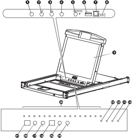
Front View
EXIT |
MENU |
LCD POWER |
UPGRADE |
|
|
|
FW UPGRADE |
|
|
Stand by |
|
|
|
|
NORMAL RECOVERY |
1 |
2 |
3 |
4 |
5 |
6 |
7 |
8 |
9 |
10 |
11 |
12 |
13 |
14 |
15 |
16 |
|
|
|
|
|
|
|
|
|
|
|
|
|
|
|
|
|
|
NUM |
CAPS |
SCROLL |
RESET |
|
|
|
|
|
|
|
|
|
|
|
|
|
|
|
LOCK |
LOCK |
LOCK |
|
|
PORT ID |
DOWN |
|
UP |
STATION ID |
DOWN |
|
UP |
|
|
|
|
|
|
|
|
|
|
aem0344b
Rack LCD Console KVM Switch User’s Manual |
3 |
Item Number Component |
Description |
|
|
EXIT button |
1. Pressing the EXIT button without opening the On Screen Display (OSD) |
|
|
initiates an auto adjustment which restores the display defaults of the OSD. |
2.While the OSD user interface is in use, press the EXIT button to exit the current menu and return to the previous menu or press the EXIT button to leave an adjustment menu when the adjustment is complete.
3.From the Main Menu screen, pressing the EXIT button, will exit the OSD.
Left/Down Arrows button Pressing this button moves left or down through the menu and decreases the
|
|
value when making an adjustment. |
|
Right/Up Arrows button |
Pressing this button moves right or up through the menu and increases the |
|
|
value when making an adjustment. |
|
MENU button |
1. If the OSD user interface has not been opened, pressing the MENU button |
|
|
initiates it and brings up the Main menu. |
|
|
2. While the OSD user interface is in use, when a setting choice is reached, |
|
|
pressing the MENU button brings up the setting’s adjustment screen. |
|
LCD POWER button |
Turns on power to the LCD monitor. An LED light next to the switch will |
|
|
illuminate when the monitor is in stand-by (power-saver) mode. |
|
USB port |
Connect a peripheral device (flash drive, CD-ROM drive) to the KVM Rack |
|
|
LCD. |
|
UPGRADE port |
An RJ-11 port to be used to transfer firmware upgrades from the |
|
|
administrator’s server to the KVM Rack LCD. |
|
FW UPGRADE |
The Firmware Upgrade switch should be in the NORMAL position during |
|
NORMAL / RECOVERY normal operation of the KVM Rack LCD. The switch is set to RECOVERY |
|
|
|
only when a Firmware Upgrade Recovery is performed. (See “Firmware |
|
|
Upgrade Recovery” on page 24 for more information.) |
|
LCD monitor |
The LCD display monitor of the KVM Rack LCD. |
|
RESET switch |
Press this recessed switch in with a small object (such as a pen point) to |
|
|
perform a system reset. |
|
SCROLL LOCK LED |
When illuminated, the SCROLL LOCK LED indicates the scroll lock function |
|
|
on the keyboard is enabled. |
|
CAPS LOCK LED |
When illuminated, the CAPS LOCK LED indicates the capitals lock function |
|
|
on the keyboard is enabled. |
|
NUM LOCK LED |
When illuminated, the NUM LOCK LED indicates the number lock function |
|
|
on the keyboard is enabled. |
|
STATION ID UP button |
Station ID selection button. Pressing the UP button repeatedly scrolls up |
|
|
through the list of available stations. |
|
STATION ID DOWN |
Station ID selection button. Pressing the DOWN button repeatedly scrolls |
|
button |
down through the list of available stations. |
|
STATION ID LED |
Two digit LED display shows the Station ID. |
|
display |
|
|
PORT ID UP button |
Port ID selection button. Pressing the UP button repeatedly scrolls up through |
|
|
the list of available ports. |
|
PORT ID DOWN button |
Port ID selection button. Pressing the DOWN button repeatedly scrolls down |
|
|
through the list of available ports. |
|
PORT ID LED display |
Two digit LED display shows the Port ID. |
|
ON LINE LED display |
When lit, indicates the computer attached to that port is up and running. |
4 |
Rack LCD Console KVM Switch User’s Manual |
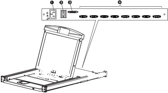
Rear View
1
CHAIN OUT |
8 |
7 |
6 |
5 |
4 |
3 |
2 |
1 |
|
0
POWER


 aem0345a
Item Number |
Component |
Description |
|
Power Socket |
Standard 3-prong AC power socket. |
|
Power Switch |
Standard ON/OFF rocker switch |
|
CHAIN OUT Port |
Port for connecting KVM stations in series to the KVM Rack LCD |
|
KVM Port Section |
The plugs for the cables that connect to the servers. |
Compatible Cables
PS2 KVM Cable |
USB KVM Cable (green overmolding) |
AP5264 |
AP5821 |
AP5250 |
AP5822 |
AP5254 |
AP5823 |
AP5258 |
|
Rack LCD Console KVM Switch User’s Manual |
5 |
Installation
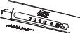
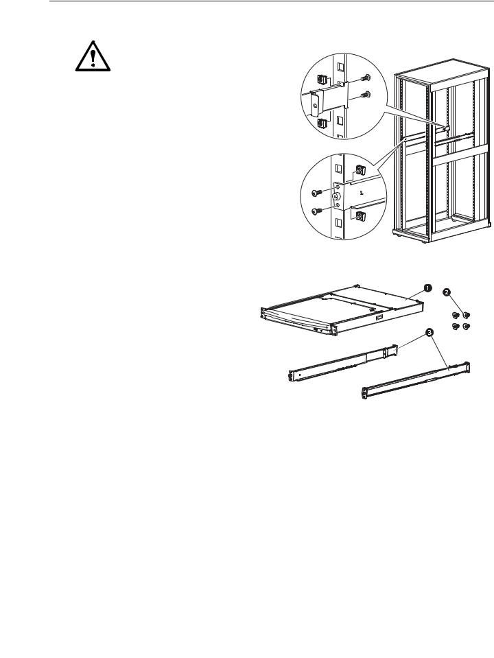
Brackets
Caution: Use only the hardware provided to install the KVM Rack LCD in the rack.
1. Attach the left and right mounting rails to the inside of the rack. The flange that supports the KVM Rack LCD station will be to the inside.
– Screw the front flanges to the rack first.
2. Slide the bars with the rear flanges toward the rack until the flanges make contact with the rack then screw the rear flanges to the rack.
na0347a
3.Slide the KVM Rack LCD ( ) onto the support flanges ( ). Use the screws ( ) supplied to loosely attach the front of the KVM Rack LCD to the front of the rack.
–Do not fully tighten the screws at this time.
6 |
Rack LCD Console KVM Switch User’s Manual |
4.Slide the rear attachment sliding brackets along the slide bars until they contact the
rear of the KVM Rack LCD. Use the supplied screws to attach the bars to the rear of the KVM Rack LCD
switch. Fully tighten these screws.
5. Slide the KVM Rack LCD open and closed two or three times to be sure it is operating smoothly.
6. If the KVM Rack LCD is moving properly in the brackets, fully tighten the screws inserted in step 3.
aem0348a
Single KVM Rack LCD Installation
In a single KVM Rack LCD installation, there are no additional KVM switches to be connected.
KVM cable installations
A custom cable is required for each server connection. The KVM end of the cable will only fit the modified SPHD port of the KVM Rack LCD or the KVM switch.
1.The USB KVM cable connects to the monitor port and to a USB port of the server
2.The PS/2 KVM cable connects to the monitor, keyboard and mouse ports of the server.
Note: The maximum distance between the KVM Rack LCD and a server is 10m (32.8 ft).
Power On the KVM Rack LCD
1.Plug the power cord into the power socket on the KVM Rack LCD and into an AC power outlet.
2.Place the power switch on the back of the KVM Rack LCD in the ON position to apply power.
Rack LCD Console KVM Switch User’s Manual |
7 |
 Loading...