


AIS 3000

AIS® 3000
10-40kVA
400V
Site Preparation and
Installation Manual


AIS® 3000 10-40kVA 400V
Site Preparation and Installation Manual
w
w
w
w
w
w
.a
.a
p
p
c
c
.c
.c
o
o
m
m
ww
w
ww
w
.apc.com
.apc.com
IMPORTANT SAFETY INSTRUCTIONS
– SAVE THESE INSTRUCTIONS
This manual contains important instructions that should be
followed during installation and maintenance of the UPS and batteries.


Contents
Safety .....................................................................1
SAVE THESE INSTRUCTIONS . . . . . . . . . . . . . . . . . . . . . . . . . . . 1
Symbols used in this guide . . . . . . . . . . . . . . . . . . . . . . . . . . . . 1
Environmental symbols . . . . . . . . . . . . . . . . . . . . . . . . . . . . . . . 2
General safety . . . . . . . . . . . . . . . . . . . . . . . . . . . . . . . . . . . . . . 2
Introduction ............................................................4
UPS Family Range and Components . . . . . . . . . . . . . . . . . . . . . 6
352mm Enclosures . . . . . . . . . . . . . . . . . . . . . . . . . . . . . . . . . . 6
523mm Enclosures . . . . . . . . . . . . . . . . . . . . . . . . . . . . . . . . . . 6
System sizes, part Nos., number of Battery Modules and
weights . . . . . . . . . . . . . . . . . . . . . . . . . . . . . . . . . . . . . . . . . . . 7
Part number coding: . . . . . . . . . . . . . . . . . . . . . . . . . . . . . . . . . 7
Battery Module . . . . . . . . . . . . . . . . . . . . . . . . . . . . . . . . . . . . . 8
Front Panel overview . . . . . . . . . . . . . . . . . . . . . . . . . . . . . . . . 8
Stabilizing Bracket . . . . . . . . . . . . . . . . . . . . . . . . . . . . . . . . . . . 9
User interface . . . . . . . . . . . . . . . . . . . . . . . . . . . . . . . . . . . . . 10
Options . . . . . . . . . . . . . . . . . . . . . . . . . . . . . . . . . . . . . . . . . 11
Battery Securing Bracket and Floor Anchoring . . . . . . . . . . . . . 11
Conduit Box . . . . . . . . . . . . . . . . . . . . . . . . . . . . . . . . . . . . . . 11
Extended Run Battery Enclosure (XR Enclosure) and Battery
Module . . . . . . . . . . . . . . . . . . . . . . . . . . . . . . . . . . . . . . . . . . 12
Part Numbers for XR Enclosures . . . . . . . . . . . . . . . . . . . . . . . 13
Part Number for Battery Module . . . . . . . . . . . . . . . . . . . . . . . 13
Maintenance Bypass Panels with Power Distribution Capability 14
Site Preparation .....................................................15
Installation Space Requirements . . . . . . . . . . . . . . . . . . . . . . . 15
Clearance for 523mm Enclosures . . . . . . . . . . . . . . . . . . . . . . . 15
Clearance for stand-alone 352mm Enclosures . . . . . . . . . . . . . 16
AIS® 3000 10-40kVA, 400V, Site Preparation and Installation Manual – 990-2258 i

Floor Anchoring Preparation . . . . . . . . . . . . . . . . . . . . . . . . . . 17
Drilling floor holes for floor anchoring . . . . . . . . . . . . . . . . . . . 17
Hole positions for floor anchors (stand-alone Enclosures) . . . . . 17
Operating Environment . . . . . . . . . . . . . . . . . . . . . . . . . . . . . 19
Operating conditions . . . . . . . . . . . . . . . . . . . . . . . . . . . . . . . . 19
Heat dissipation . . . . . . . . . . . . . . . . . . . . . . . . . . . . . . . . . . . 19
Audible noise . . . . . . . . . . . . . . . . . . . . . . . . . . . . . . . . . . . . . 19
Recommended source connections . . . . . . . . . . . . . . . . . . . . . 20
Recommended current protection . . . . . . . . . . . . . . . . . . . . . . 21
Minimum setting of breakers for 10kVA UPS . . . . . . . . . . . . . . 22
Minimum setting of breakers for 15kVA UPS . . . . . . . . . . . . . . 22
Minimum setting of breakers for 20kVA UPS . . . . . . . . . . . . . . 23
Minimum setting of breakers for 30kVA UPS . . . . . . . . . . . . . . 23
Minimum setting of breakers for 40kVA UPS . . . . . . . . . . . . . . 24
Recommended phase-conductor sizes for a 30°C
temperature environment . . . . . . . . . . . . . . . . . . . . . . . . . . . . 24
EPO switch wiring . . . . . . . . . . . . . . . . . . . . . . . . . . . . . . . . . . 25
Basic Wiring Overview . . . . . . . . . . . . . . . . . . . . . . . . . . . . . . 26
Site Preparation Checklist . . . . . . . . . . . . . . . . . . . . . . . . . . . . 27
Electrical Installation ............................................ 28
Total-Power-Off Procedure . . . . . . . . . . . . . . . . . . . . . . . . . . . 28
Front Panel . . . . . . . . . . . . . . . . . . . . . . . . . . . . . . . . . . . . . . . 30
Removal . . . . . . . . . . . . . . . . . . . . . . . . . . . . . . . . . . . . . . . . . 30
Installation . . . . . . . . . . . . . . . . . . . . . . . . . . . . . . . . . . . . . . . 31
System-Electrical Information . . . . . . . . . . . . . . . . . . . . . . . . . 32
Source connections . . . . . . . . . . . . . . . . . . . . . . . . . . . . . . . . . 33
Wiring . . . . . . . . . . . . . . . . . . . . . . . . . . . . . . . . . . . . . . . . . . 34
Input/Output Wiring – Single Mains (default) . . . . . . . . . . . . . 35
Wiring procedure - single mains . . . . . . . . . . . . . . . . . . . . . . . 35
Input/Output Wiring – Dual Mains . . . . . . . . . . . . . . . . . . . . . 37
Wiring procedure - dual mains . . . . . . . . . . . . . . . . . . . . . . . . . 37
ii AIS® 3000 10-40kVA, 400V, Site Preparation and Installation Manual – 990-2258

Communication Wiring to EPO and Optional Equipment . . . . 39
Pin connections J106 (XR Enclosure) and J108 (EPO) . . . . . . . 39
Pin connections J106 (UPS) to J200 (XR Enclosure - option) . . . 40
XR Enclosure, APC Maintenance Bypass Panel, and Generator
Control wiring . . . . . . . . . . . . . . . . . . . . . . . . . . . . . . . . . . . . . 40
Pin connections J108 (for EPO wiring options) . . . . . . . . . . . . 41
General Charge Setting . . . . . . . . . . . . . . . . . . . . . . . . . . . . . 42
Charge setting procedure . . . . . . . . . . . . . . . . . . . . . . . . . . . . 42
Leveling Feet . . . . . . . . . . . . . . . . . . . . . . . . . . . . . . . . . . . . . 43
Setting the leveling feet . . . . . . . . . . . . . . . . . . . . . . . . . . . . . 43
Floor Anchoring (option) . . . . . . . . . . . . . . . . . . . . . . . . . . . . 44
Floor anchoring of stand-alone systems . . . . . . . . . . . . . . . . . . 44
Battery securing . . . . . . . . . . . . . . . . . . . . . . . . . . . . . . . . . . . 45
Wiring Verification Procedure . . . . . . . . . . . . . . . . . . . . . . . . . 46
Installation Site Checklist . . . . . . . . . . . . . . . . . . . . . . . . . . . . 48
LIMITED FACTORY WARRANTY . . . . . . . . . . . . . . . . . . . . . . . . 49
APC product covered . . . . . . . . . . . . . . . . . . . . . . . . . . . . . . . . 49
Terms of warranty . . . . . . . . . . . . . . . . . . . . . . . . . . . . . . . . . . 49
Non-transferable warranty extends to first purchaser for use . . 49
Assignment of warranties . . . . . . . . . . . . . . . . . . . . . . . . . . . . 49
Drawings, descriptions . . . . . . . . . . . . . . . . . . . . . . . . . . . . . . 50
Warranty claims procedure . . . . . . . . . . . . . . . . . . . . . . . . . . . 50
Exclusions . . . . . . . . . . . . . . . . . . . . . . . . . . . . . . . . . . . . . . . . 50
AIS® 3000 10-40kVA, 400V, Site Preparation and Installation Manual – 990-2258 iii

Smart-UPS® VT 10-30kVA, 208V, Site Preparation and Installation – 990-1598
Safety
SAVE THESE INSTRUCTIONS
This guide contains important instructions that should be followed when handling the UPS, Battery
Enclosures, and Batteries.
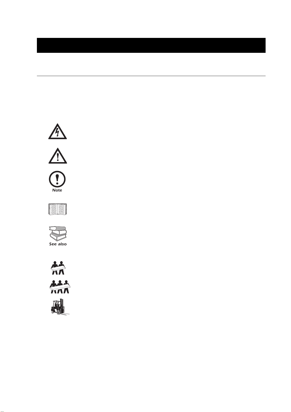
Symbols used in this guide
WARNING!
Risk of electric shock.
CAUTION!
Read this information to avoid equipment damage.
Indicates important information.
Indicates that more information is available on this subject in a different section of this
manual.
Indicates that more information is available on the same subject in a different manual.
Two people to lift a component weighing between 18 - 32 kg.
Three people to lift a component weighing between 32 - 54 kg.
Use a pallet jack or a forklift for components over 54 kg.
AIS® 3000 10-40kVA, 400V, Site Preparation and Installation Manual – 990-2258 1
Safety – SAVE THESE INSTRUCTIONS
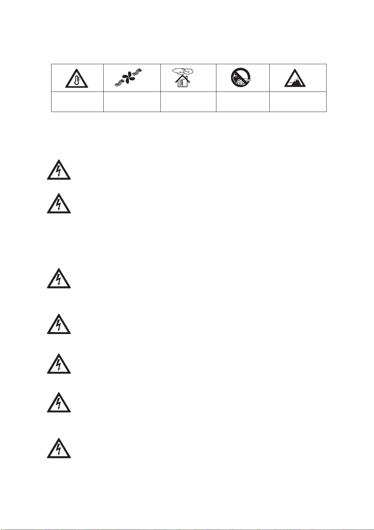
Environmental symbols
Temperature Ventilation
General safety
Humidity Dust/Fumes Altitude
requirements
WARNING!
All electrical power and control wiring must be installed by a qualified electrician and
comply with local and national codes.
WARNING!
When connected, the UPS contains energy from both AC and DC sources. If the UPS
has dual mains supply, be aware of the two AC supply sources. Risk of electric shock -
parts inside the UPS are energized from the battery supply even the AC power is
disconnected. Follow the Total-Power-Off procedure in this manual to completely de-
energize the system. Disconnect charging source prior to connecting or disconnecting
battery terminals.
WARNING!
Servicing of batteries should be performed or supervised by personnel knowledgeable
of batteries and the required precautions. Keep unauthorized personnel away from
batteries.
WARNING!
Batteries do not contain serviceable parts. Only APC authorized personnel may open
batteries.
WARNING!
Do not dispose of battery or batteries in a fire. The battery may explode. Do not open or
mutilate the battery or batteries. Released electrolyte is harmful to the skin and eyes. It
may be toxic.
WARNING!
Risk of Energy Hazard, 96 V, 7.2 Ampere-hour battery. Before replacing batteries,
remove watches, rings, or other metal objects. High energy through conductive
materials could cause severe burns.
WARNING!
When handling batteries, wear rubber gloves and boots. Do not lay tools or metal
objects on top of batteries.
2 AIS® 3000 10-40kVA, 400V, Site Preparation and Installation Manual – 990-2258

Safety – SAVE THESE INSTRUCTIONS
WARNING!
When replacing a Battery Unit, replace with the same number of the: APC SYBT1
(always replace a whole Battery Module (4 Battery Units) at a time).
WARNING!
Only trained personnel familiar with the construction and operation of the equipment
and the electrical and mechanical hazards involved, may install and remove system
components.
CAUTION!
Wait until you are ready to power up the system before installing Battery Modules in the
UPS. Failure to do so can result in a deep discharge of the batteries and cause permanent
damage. The time from the battery installation time till the UPS is powered up should
not exceed 72 hours or 3 days.
For configurations including customer-supplied external batteries, refer to
manufacturer’s battery installation and maintenance instructions.
AIS® 3000 10-40kVA, 400V, Site Preparation and Installation Manual – 990-2258 3
Introduction
Welcome to the Site Preparation and Installation Manual for the AIS® 3000. This manual contains
information on how to prepare your site for the installation of the UPS and optional APC equipment
(also available at www.apc.com) and instructions on how to carry out the electrical and mechanical
installation.
Separate manuals are available on:
• Receiving and Unpacking - part # 990-1961
• Operation - part # 990-2259
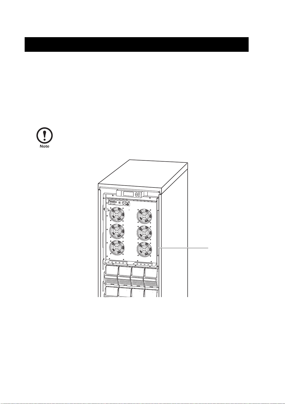
The user manuals are provided in the documentation storage area at the top right corner
on the UPS (behind the Front Panel).
Output
Pwr
!
Zone
Probe
10/100Base-T
Reset
10/100
AP9619 Network Management Card EM
Documentation
storage
Serial:
Model:
Serial:
Model:
BATTERY UNIT
Serial:
Model:
BATTERY UNIT
Serial:
Model:
BATTERY UNIT
BATTERY UNIT
Serial:
Model:
Serial:
Model:
BATTERY UNIT
BATTERY UNIT
Serial:
Model:
Serial:
Model:
BATTERY UNIT
BATTERY UNIT
4 AIS® 3000 10-40kVA, 400V, Site Preparation and Installation Manual – 990-2258

Introduction – SAVE THESE INSTRUCTIONS
For more information on APC products and services, visit us at www.apc.com
Most illustrations show 523mm Enclosures but apply to both Enclosure sizes. Any
differences between the two Enclosure sizes will be addressed in the manual.
AIS® 3000 10-40kVA, 400V, Site Preparation and Installation Manual – 990-2258 5
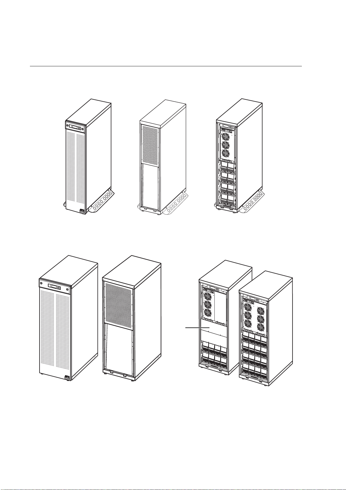
UPS Family Range and Components
352mm Enclosures
!
O
u
tput
Pw
r
Zo
n
e
P
r
ob
e
10/10
0
Ba
s
e-T
Reset
1
0
/10
AP9619 Network Management C
0
a
rd
E
M
Se
r
i
al
:
M
od
el:
BA
T
T
ERY UNIT
Seri
a
l:
M
o
del
:
BAT
T
E
R
Y
U
NIT
Ser
i
a
l:
Mo
del:
BA
T
T
E
R
Y
UN
I
T
S
e
r
i
a
l
:
M
o
d
el:
B
ATTERY UNIT
Ser
i
al
:
Mo
del:
BA
T
T
ERY UNIT
S
e
r
i
al
:
M
od
el:
B
A
T
T
ERY UN
I
T
Se
r
ia
l
:
M
od
e
l
:
BA
TTE
R
Y UN
IT
Se
r
ia
l
:
M
od
el:
BATTERY
UNIT
www.apc.com
www.apc.com
Front view Rear view Front view without cover
10-20kVA
523mm Enclosures
www.apc.com
www.apc.com
Front view Rear view
Blind plates
cover
empty battery
bays
Front view without cover
10-20kVA
!
Out
put
Pw
r
Zo
ne
Probe
10
R
/100
es
e
t
Bas
e-T
AP96
19
Net
1
w
0
ork Manage
/100
m
ent Ca
rd E
M
!
O
u
tput
Pwr
Zone
P
r
ob
e
10/100Base-T
R
e
set
AP96
1
9 Net
10/1
w
or
k
00
Management Card EM
S
erial
:
Mo
d
el
:
BATTERY UNIT
Se
ri
al
:
Mode
l
:
BATTERY UNIT
Ser
i
al:
Mode
l
:
BATTERY UNIT
S
e
ri
a
l:
M
o
d
el:
Serial:
Model:
BATTERY UNIT
S
er
ial:
M
o
del:
BATTERY UNIT
Serial:
Model:
BATTERY UNIT
S
er
ial:
Model:
Serial:
Model:
BATTERY UNIT
BATTERY UNIT
Serial:
Model:
BATTERY UNIT
Serial:
Model:
BATTERY UNIT
Serial:
Model:
BATTERY UNIT
Serial:
M
o
d
e
l:
BATTERY UNIT
Se
r
i
a
l:
Mo
d
e
l:
BATTERY UNIT
Serial:
M
o
del:
BATTERY UNIT
BATTERY UNIT
Serial
:
Mod
e
l:
BATTERY UNIT
S
er
i
a
l
:
Mod
e
l
:
BATTERY UNIT
Serial:
Model:
BATTERY UNIT
Serial:
Model:
BATTERY UNIT
S
e
ri
al:
Model:
BATTERY UNIT
Seri
al
:
Model:
BATTERY UNIT
Serial:
Model:
BATTERY UNIT
Serial:
Model:
BATTERY UNIT
Serial:
Model:
BATTERY UNIT
Front view without cover
30-40kVA
6 AIS® 3000 10-40kVA, 400V, Site Preparation and Installation Manual – 990-2258

Introduction – UPS Family Range and Components
System sizes, part Nos., number of Battery Modules and weights
Height (identical for all Enclosure sizes) 1490mm
Depth (identical for all Enclosure sizes) 854mm
System Size/ Enclosure
width
APC Part No. kg APC Part No. kg
Installed weight Installed weight
10kVA 352mm ISVT10KH1B2S 308.7 ISVT10KH2B2S 404.7
10kVA 523mm ISVT10KH1B4S 345.4 ISVT10KH2B4S 441.4
10kVA 523mm ISVT10KH3B4S 537.4 ISVT10KH4B4S 633.4
15kVA 352mm ISVT15KH2B2S 404.7
15kVA 523mm ISVT15KH2B4S 441.4 ISVT15KH3B4 537.4
15kVA 523mm ISVT15KH4B4S 633.4
20kVA 352mm ISVT20KH2B2S 404.7
20kVA 523mm ISVT20KH2B4S 472.0 ISVT20KH3B4S 568.0
20kVA 523mm ISVT20KH4B4S 664.0
30kVA 523mm ISVT30KH3B4S 569.0 ISVT30KH4B4S 665.0
40kVA 523mm ISVT40KH4B4S 665.0
Part number coding:
ISVT10KH1B2S
ISVT 10K H 1B 2* S
Product
kVA
Voltage
1 Batt.
Module
*) 4 = max. 4 Battery Modules
With
start-up
service
Max.
2 Batt.
Modules
AIS® 3000 10-40kVA, 400V, Site Preparation and Installation Manual – 990-2258 7

Introduction – UPS Family Range and Components
Battery Module
One Battery Module consists of 4 Battery Units (shipping in the UPS Enclosure).
S
e
rial:
Mod
e
l
:
BATTERY
UNIT
Seri
a
l:
M
o
de
l
:
BA
TTE
RY U
N
I
T
S
e
r
i
a
l
:
Mod
el
:
BATT
E
RY UN
I
T
Ser
i
a
l
:
M
o
de
l
:
BA
TTE
R
Y
U
NIT
4 x 24kg
Front Panel overview
w
w
w
w
w
w
.a
.a
p
p
c
c
.c
.c
o
o
m
Front Panel
for 352mm
Enclosure
m
Rear view of
Front Panel
for 352mm
Enclosure
with filters
Filter seen
from front
and rear
Front Panel
for 523mm
Enclosure
w
w
w
w
w
w
.a
.
a
p
p
c
c
.
.
c
c
o
o
m
m
Rear view of
Front Panel
for 523mm
Enclosure
with filters
Filter seen
from front
and rear
Front Panel attachment procedure described in the Front Panel section.
8 AIS® 3000 10-40kVA, 400V, Site Preparation and Installation Manual – 990-2258
Introduction – UPS Family Range and Components
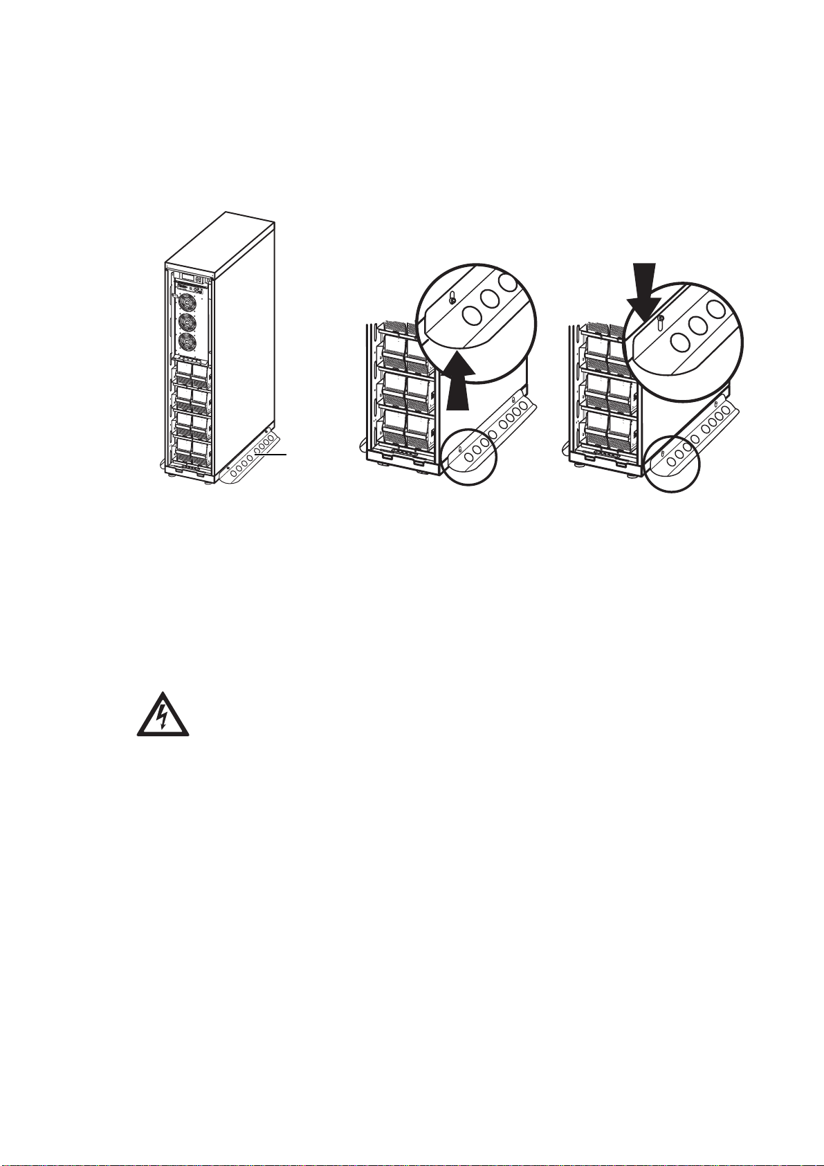
Stabilizing Bracket
Always install the Stabilizing Brackets on the 352mm Enclosure (shipped with the UPS) to enhance
the stability of the Enclosure.
!
Ou
tpu
t
Pwr
Z
o
ne
Probe
10/100Base-T
Re
se
t
10
/
1
0
AP9
0
6
1
9
Ne
twor
k
M
a
n
a
gem
e
n
t
C
ard
E
M
S
erial:
M
od
e
l
:
BATTERY UNIT
Serial:
M
ode
l
:
BATTERY UNIT
Se
r
i
a
l
:
M
odel
:
BATT
ER
Y
UNI
T
Se
r
i
al:
M
od
el:
BATTE
R
Y
U
NI
T
S
e
r
i
al
:
Mo
del
:
BA
T
T
E
R
Y
U
N
IT
Serial
:
Mod
el
:
B
AT
T
E
RY
U
N
IT
Se
r
ia
l
:
M
od
e
l
:
BATTERY UNIT
S
e
r
i
al
:
M
o
d
el:
BA
TTERY UN
IT
Se
rial
:
Mo
del
:
BATTERY UNIT
Ser
i
al
:
M
od
el
:
BATTERY UNIT
Stabilizing
Se
ria
l
:
Model:
BATTERY UNIT
Seria
l
:
M
odel:
BATTERY UNIT
Se
ri
al:
Model:
BATTERY UNIT
S
e
ria
l
:
Mo
de
l
:
BATTERY UNIT
Bracket
Serial:
M
od
e
l
:
BATTERY UNIT
Se
ri
al
:
M
ode
l
:
BATTERY UNIT
Se
r
i
al:
Model:
BATTERY UNIT
Ser
i
a
l:
Mod
e
l
:
BATTERY UNIT
Seri
al
:
M
o
de
l
:
BATTERY UNIT
S
eri
a
l:
Model:
BATTERY UNIT
If the Enclosure needs to be moved after Stabilizing Brackets have been attached to the Enclosure,
the Stabilizing Brackets must be pushed up into their high position.
Loosen the two screws of both Stabilizing Brackets, and push the bracket up into the high
position.
When the Enclosure has reached its new position, push the Bracket into its “down” position
again, and tighten the screws.
WARNING!
For stability reasons, do not remove Stabilizing Brackets from 352mm Enclosures.
AIS® 3000 10-40kVA, 400V, Site Preparation and Installation Manual – 990-2258 9
Introduction – UPS Family Range and Components
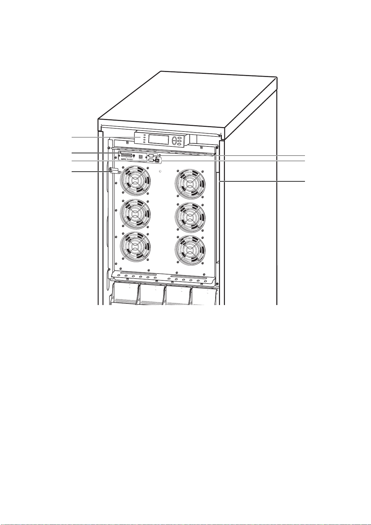
User interface
Output
Pwr
!
Zone
Probe
10/100Base-T
Reset
10/100
AP9619 Network Management Card EM
Serial:
Model:
BATTERY UNIT
Display: user-control interface used to configure the functionality, monitor the system, set alarm
Serial:
Model:
BATTERY UNIT
Serial:
Model:
BATTERY UNIT
Serial:
Model:
BATTERY UNIT
thresholds, and to provide audible and visual alarms.
Network Management Card with Environmental Monitor (AP9619): used for remote system
control and monitoring, e-mail notifications etc. See separate manual for the AP9619.
®
Computer-interface port for the connection of computers with APC Powerchute
Mechanical Bypass Lever: used to bypass the upstream mains power around the UPS to support
software.
the load directly = internal mechanical bypass operation.
Service port (for APC maintenance personnel only).
Display port for the connection of display communication cable.
Documentation storage.
10 AIS® 3000 10-40kVA, 400V, Site Preparation and Installation Manual – 990-2258
 Loading...