


 Loading...
Allied Telesis AT-X510-28GPX, AT-X510-28GSX, AT-X510-28GTX, AT-X510-52GPX, AT-X510-52GTX User Manual
AMF (Allied Telesis Management Framework) |
Software Reference Supplement for x-Series Switches |
AlliedWare Plus™ Operating System |
Version 5.4.3 |
SwitchBlade® x8112 |
SwitchBlade® x908
x900-24XS and x900-24XT
x900-12XT/S
x610-24Ts and x610-24Ts/X |
AT-x510-28GTX and AT-x510-52GTX |
x610-48Ts and x610-48Ts/X |
AT-x510-28GPX and AT-x510-52GPX |
x610-24Ts-PoE+ and x610-24Ts/X-PoE+ |
AT-x510-28GSX |
x610-48Ts-PoE+ and x610-48Ts/X-PoE+ |
|
x610-24SPs/X |
|
C613-50031-01-REV A |
|

Acknowledgments
This product includes software developed by the University of California, Berkeley and its contributors.
Copyright ©1982, 1986, 1990, 1991, 1993 The Regents of the University of California. All rights reserved.
This product includes software developed by the OpenSSL Project for use in the OpenSSL Toolkit (http://www.openssl.org/).
Copyright ©1998-2008 The OpenSSL Project. All rights reserved.
This product includes software licensed under the GNU General Public License available from:
http://www.gnu.org/licenses/gpl2.html
Source code for all GPL licensed software in this product can be obtained from the
Allied Telesis GPL Code Download Center at:
http://www.alliedtelesis.com/support/default.aspx
Allied Telesis is committed to meeting the requirements of the open source licenses including the GNU General Public License (GPL) and will make all required source code available.
If you would like a copy of the GPL source code contained in Allied Telesis products, please send us a request by registered mail including a check for US$15 to cover production and shipping costs and a CD with the GPL code will be mailed to you.
GPL Code Request
Allied Telesis Labs (Ltd)
PO Box 8011
Christchurch.
New Zealand
©2013 Allied Telesis Inc. All rights reserved.
This documentation is subject to change without notice. No part of this publication may be reproduced, stored in a retrieval system, or transmitted in any form or any means electronic or mechanical, including photocopying and recording for any purpose other than the purchaser’s internal use without the written permission of Allied Telesis, Inc.
Allied Telesis, AlliedWare Plus, EPSRing, SwitchBlade, and VCStack are trademarks or registered trademarks in the United States and elsewhere of Allied Telesis, Inc. Adobe, Acrobat, and Reader are either registered trademarks or trademarks of Adobe Systems Incorporated in the United States and/or other countries. Additional brands, names and products mentioned herein may be trademarks of their respective companies.
|
AMF Software Reference Supplement for Allied Telesis x-Series Switches |
|
2 |
AlliedWare PlusTM Operating System - Software Version 5.4.3-1.4 and later |
C613-50031-01 REV A |

Contents of this Software Reference
Supplement
This document introduces AMF for Allied Telesis x-series switches. It contains the following introductory material on AMF, including links to related information.
■Introduction to AMF on page 5
■How To Configure and Use AMF on Allied Telesis Switches on page 9
■AMF Commands on page 49
Getting the most from this manual
Although you can view this document using Acrobat version 5, to get the best from this manual, we recommend using Adobe Acrobat Reader version 8. You can download Acrobat Reader 8 free from http://www.adobe.com/.
|
AMF Software Reference Supplement for Allied Telesis x-Series Switches |
|
C613-50031-01 REV A |
AlliedWare PlusTM Operating System - Software Version 5.4.3-1.4 and later |
3 |

|
AMF Software Reference Supplement for Allied Telesis x-Series Switches |
|
4 |
AlliedWare PlusTM Operating System - Software Version 5.4.3-1.4 and later |
C613-50031-01 REV A |
Introduction to AMF
AMF, the Allied Telesis Management Framework, is a suite of network management features that simplify management of its member switches—from the network core out to its edge.
AMF simplifies switch recovery and firmware replacements and upgrades. It greatly reduces the network management and maintenance overhead.
AMF Capable Products and Software
AMF is supported on the following products when running software version 5.3.4-1.4 or later:
■Switchblade™ x8100 series switches.
■Switchblade™ x908 series switches.
■x900 series switches.
■x610 series switches.
■x510 series switches.
For additional information on AMF, its configuration and its operation on Allied Telesis switches, watch the following videos from our YouTube channel.
AMF overview videos
Video |
Topic |
|
Click the following link to view the video |
|
Introduction to Software Defined Networking (SDN): |
|
www.youtube.com/watch?v=bQRVe6TMtRU |
Click the following link to view the video Introducing
AMF:
www.youtube.com/watch?v=pkQbWFuwJQg
|
AMF Software Reference Supplement for Allied Telesis x-Series Switches |
|
C613-50031-01 REV A |
AlliedWare PlusTM Operating System - Software Version 5.4.3-1.4 and later |
5 |

Video |
Topic |
|
Click the following link to view the video AMF |
|
Centralized Network Management: |
|
www.youtube.com/watch?v=zhEnqc-YMI8 |
Click the following link to view the video Autoprovisioning:
www.youtube.com/watch?v=bQRVe6TMtRU
Click the following link to view the video Auto-
Upgrade:
www.youtube.com/watch?v=K0o6sWSfjZ0
|
AMF Software Reference Supplement for Allied Telesis x-Series Switches |
|
6 |
AlliedWare PlusTM Operating System - Software Version 5.4.3-1.4 and later |
C613-50031-01 REV A |
Video |
Topic |
|
Click the following link to view the video Auto |
|
Network Backup: |
|
www.youtube.com/watch?v=wwe8S3sXLjk |
Click the following link to view the video AMF Live
Demo: Zero-Touch Auto Recovery:
www.youtube.com/watch?v=txiGcb4BveM
|
AMF Software Reference Supplement for Allied Telesis x-Series Switches |
|
C613-50031-01 REV A |
AlliedWare PlusTM Operating System - Software Version 5.4.3-1.4 and later |
7 |

|
AMF Software Reference Supplement for Allied Telesis x-Series Switches |
|
8 |
AlliedWare PlusTM Operating System - Software Version 5.4.3-1.4 and later |
C613-50031-01 REV A |
Technical Guide
How To | Configure and Use AMF on Allied Telesis Switches
Introduction
The Allied Telesis Management Framework (AMF) is a suite of features that combine to simplify network management across all supported network devices from the core to the edge.
AMF also provides simplified unit recovery and firmware upgrade management. The primary function of AMF is to reduce the management and maintenance overhead on a network, while improving on responsiveness and handling of device failures within the network.
What information will you find in this document?
This How To Note describes AMF along with its benefits, concepts, and configuration guidelines. For more information on the commands used in this How To note, see the AMF Commands chapter later included within this document. Also for those who would like to know more about AMF, see the Introduction to AMF.
Which products and software version does it apply to?
This How To Note applies to the following Allied Telesis switches running AlliedWare Plus OS software version 5.4.3 or later:
SwitchBlade™ x8100 family
SwitchBlade™ x908 series switches
x900 series switches
x610 series switches
x510 series switches
C613-16174-00 REV D |
|
|
|
|
|
alliedtelesis.com x |
|
|
|
|
|
||
|
|
|
|
|
||
|
|
|
|
|
|
Introduction |
Contents |
|
Introduction............................................................................................................................................................................. |
9 |
What information will you find in this document?................................................................................... |
9 |
Which products and software version does it apply to? ..................................................................... |
9 |
Software feature licensing ................................................................................................................................... |
11 |
The key benefits of AMF .............................................................................................................................................. |
12 |
Unified command-line ......................................................................................................................................... |
12 |
Configuration backup and recovery ............................................................................................................ |
12 |
Rolling firmware upgrade .................................................................................................................................... |
12 |
AMF concepts..................................................................................................................................................................... |
13 |
Network name.......................................................................................................................................................... |
13 |
Node............................................................................................................................................................................... |
13 |
Master nodes.............................................................................................................................................................. |
13 |
Domains........................................................................................................................................................................ |
13 |
Core distance............................................................................................................................................................. |
14 |
Links................................................................................................................................................................................. |
15 |
Crosslinks...................................................................................................................................................................... |
15 |
Working-sets .............................................................................................................................................................. |
16 |
AMF network guidelines ............................................................................................................................................... |
16 |
Retention and use of the ‘manager’ username....................................................................................... |
16 |
Loop-free data plane ............................................................................................................................................. |
17 |
Aggregators................................................................................................................................................................. |
17 |
VCStacks....................................................................................................................................................................... |
17 |
AMF external removable media...................................................................................................................... |
17 |
AMF interaction with QoS and ACLs.......................................................................................................... |
18 |
NTP and AMF ........................................................................................................................................................... |
18 |
Configuring AMF ............................................................................................................................................................... |
19 |
Simple AMF example with a single master ............................................................................................... |
19 |
Verifying the AMF network................................................................................................................................ |
24 |
Using the AMF network................................................................................................................................................ |
25 |
AMF backups.............................................................................................................................................................. |
25 |
Safe removal of external storage media..................................................................................................... |
26 |
Performing a manual backup ...................................................................................................................................... |
27 |
Backups on VCStacks running as AMF masters .............................................................................................. |
28 |
Node recovery................................................................................................................................................................... |
30 |
Automatic node recovery .................................................................................................................................. |
30 |
A “Clean” node ........................................................................................................................................................ |
31 |
Manual node recovery.......................................................................................................................................... |
31 |
Node recovery on VCStacks............................................................................................................................ |
32 |
AMF safe configuration.................................................................................................................................................. |
34 |
How can I undo a safe configuration?.......................................................................................................... |
35 |
Page 10 | How to Configure and Use AMF on Allied Telesis Switches
|
I n trod u ction |
Adding a preconfigured device to the network |
..............................................................................................36 |
Using the unified CLI with working-sets............................................................................................................... |
38 |
The working-set........................................................................................................................................................ |
38 |
Working-set groups ................................................................................................................................................ |
38 |
Automatic working-set groups......................................................................................................................... |
39 |
User-defined working-set groups.................................................................................................................... |
40 |
Executing commands on working-sets ........................................................................................................ |
41 |
Interactive commands ........................................................................................................................................... |
43 |
Rolling-reboot firmware upgrade............................................................................................................................. |
44 |
Performing a rolling reboot upgrade............................................................................................................. |
45 |
Software feature licensing
A feature licence is required for each AMF master node in the AMF network. AMF master node licences are available for the SBx8100 and SBx908 platforms. A licence is not required for AMF member nodes.
How to Configure and Use AMF on Allied Telesis Switches | Page 11
The key benefits of AMF
The key benefits of AMF
The key benefits of AMF include its: unified command-line, simple configuration backup and recovery process, and time-saving rolling firmware upgrade.
Unified command-line
The primary means of configuring and controlling AlliedWare Plus (AW+) units is via a textbased command-line interface. In existing networks, this command-line is available via a serial console port as well as remote login sessions (e.g. SSH).
Under AMF, this concept is extended to allow control of an entire network of AW+ devices (or any part thereof) via a single session. It allows a network administrator to nominate all nodes or a subset of nodes within the AMF network, known as a working-set. Commands can then execute concurrently across all nodes in the nominated working-set as if it were a single unit. Any existing configuration or diagnostic actions can thus be applied to multiple devices, reducing repetitive and error-prone roll-out procedures. In this way, regularities in network design can be used to reduce maintenance cost and complexity, while still retaining complete flexibility in network design and control. Currently AMF supports a network of up to 42 nodes, and multiple AMF networks can exist side by side across a single physical network. A Virtual Chassis Stack (VCStack) is considered to be just one node by AMF.
Configuration backup and recovery
An AMF network has a master node that uses external storage to automatically backup complete configuration information of all the other nodes, including boot configuration, firmware, licenses, and user scripts. If a node subsequently fails, the AMF will automatically recognize and reconfigure an unconfigured replacement unit, completely recreating the stored state of the failed unit into the replacement unit. This new unit will then reboot and resume service, without any need for user intervention beyond physical hardware replacement. In this way AMF provides a complete zero-touch recovery solution.
If preferred (or if automatic recovery fails), the new hardware will be held in a safe nonforwarding state—ready for a network administrator to configure remotely via the AMF unified command-line.
Rolling firmware upgrade
Firmware upgrades on a production network are typically an infrequent but sensitive and labour-intensive process. AMF supports automated firmware roll-out to a user-selected subset of nodes. The user selects a target group of nodes, and the location where the new firmware is stored, then AMF takes care of the rest. Nodes are upgraded in a serial fashion, with each node tested before continuing with subsequent nodes.
If an upgrade fails, the upgrade process is automatically terminated and that node is reverted to the previous firmware version. In this way firmware updates are almost completely handsfree, while providing confidence that a bad update will not result in loss of service.
Page 12 | How to Configure and Use AMF on Allied Telesis Switches
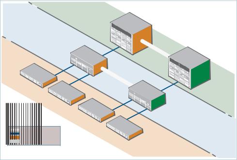
AMF concepts
AMF concepts
Network name
The AMF network name is used to determine the AMF network a node belongs to. All nodes within an AMF network must be configured with the same AMF name.
Node
AMF members are commonly referred to as nodes. A node can be a single switch, or a VCStack.
Master nodes
AMF master nodes are user defined and form the core domain of the AMF network. They are:
responsible for performing file system backups of all nodes in the AMF network.
required before an AMF network can form; at least one must be present.
AMF master nodes are supported on SBx908 and SBx8100 platforms; an AMF licence is required for each master. Only one AMF master license is required even if two CFCs are installed. The license is for the chassis, not the CFC.
Notes: A VCStack needs to have consistent licensing on all stack members, so an AMF master license would be required on both devices in an SBx908 stack.
When more than one AMF master node exists in an AMF network, it is important to know that these operate completely independently of each other, and there is no synchronization between AMF master nodes.
For redundancy, you can have multiple master nodes, each acting as a master for the network. But, there is no synchronization of status or data files between the masters. The behaviour of a master node is not changed at all by the presence of other master nodes.
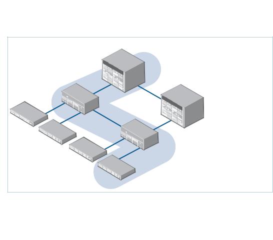
Domains
Every AMF node belongs to an AMF domain, which may be comprised of multiple nodes or only a single node. AMF master nodes are included in the core domain, and all other domains are rooted in the core domain. AMF domains are determined by AMF crosslinks, (see page 15). All nodes connected via AMF crosslinks are part of the same domain, and
How to Configure and Use AMF on Allied Telesis Switches | Page 13
AMF concepts
nodes connected via regular AMF links will be part of a higher or lower domain depending on whether they are closer to or further away from the core domain. Nodes within a domain must be connected in either a chain or ring topology.
This means that a maximum of two crosslinks should be configured on any single node. The advantage of an AMF domain is that two links from a domain to a single higher level domain (closer to the core) will provide redundant AMF links. It is recommended that an AMF domain should only be connected to a single higher level domain, though it may be connected to multiple lower level domains.
It is recommended that:
The maximum number of nodes per domain is 12 for SBx8100, x908, x900, x610, and x510.
Core distance
This is the distance (hop count) between a domain and the Core domain. The Core domain has a Core distance of 0, and the maximum recommended Core distance in an AMF network is 8.
|
|
|
|
|
|
|
|
|
|
Master |
AMF |
|
|
|
|
|
|
|
|
|
|
|
|
|
|
|
Node ID1 |
|
node |
|
|
|
|
|
|
|
|||
|
|
|
|
|
|
|
|
|
|
|
|
|
|
|
|
|
|||
|
|
|
|
|
|
|
|
|
|
|
|
|
|
|
|
|
|
|
|
|
|
|
|
|
|
AMF |
|
|
|
|
|
|
|
|
|
AMF |
|
|
|
|
|
|
Node ID3 |
Member |
|
|
|
|
|
|
|
|
Master |
|
|
||||
|
|
|
node |
|
|
|
|
|
|
|
node |
|
|
||||||
|
AMF |
|
|
|
|
|
|
|
|
|
|
Node ID2 |
|
|
|
|
|||
|
|
|
|
|
|
|
|
|
|
|
|
|
|
|
|
||||
|
|
|
|
|
|
|
|
|
|
|
|
|
|
|
|
|
|
||
Member |
node |
|
|
|
|
|
|
|
|
|
|
|
|
|
|
|
|
|
|
Node ID5 |
|
|
|
|
|
|
|
|
|
|
AMF |
|
|
|
|
|
|||
|
|
|
AMF |
|
|
|
|
|
|
|
|
|
CORE |
|
|||||
|
|
|
|
|
|
|
|
|
|
|
|
|
|
||||||
|
|
|
|
|
|
|
Node ID4 |
Member |
|
|
|
|
|
|
|||||
|
|
|
Member |
node |
|
|
|
node |
|
|
|
DISTANCE |
|||||||
|
|
|
|
|
|
|
|
|
|
|
|
|
|
||||||
|
|
Node ID6 |
|
|
AMF |
|
|
|
|
|
|
|
|
||||||
|
|
|
|
|
|
|
|
|
|
|
|
|
|
|
|||||
|
|
|
|
|
|
|
|
|
|
|
|
|
|
|
|
|
|||
|
|
|
|
|
|
|
|
|
|
|
|
|
|
|
|
|
0 |
||
|
|
|
|
|
|
Member |
node |
|
|
|
|
|
|
CORE |
|
|
|
|
|
|
|
|
|
|
Node ID7 |
|
AMF |
|
|
DISTANCE |
|
|
|||||||
|
|
|
|
|
|
|
|
|
|
|
|||||||||
|
|
|
|
|
|
|
|
|
|
|
|
|
|
|
|||||
amf-crosslink |
|
|
|
|
|
|
Member |
node |
|
|
|
1 |
|
||||||
|
|
|
|
|
|
|
|
|
|
|
|
|
|
||||||
amf-link |
|
|
|
|
|
|
|
Node ID8 |
|
|
|
|
|
|
|
|
|||
|
|
|
|
|
|
|
|
|
CORE |
|
|
|
|
|
|
||||
Domain Controller |
|
|
|
|
|
|
|
|
|
|
|
|
|
|
|
||||
Backup Domain Controller |
|
|
|
|
|
|
|
|
DISTANCE |
|
|
|
|
|
|||||
|
|
|
|
|
|
|
|
|
|
|
|
|
|
|
|
|
|||
|
|
|
|
|
|
|
|
|
|
|
|
|
|
2 |
|
|
|
|
|
|
|
|
|
|
|
|
|
|
|
|
|
|
|
|
|
|
|
|
|
Figure 1: AMF domains and Core distance |
|
|
|
|
|
|
|
|
|
|
|
|
|||||||
Page 14 | How to Configure and Use AMF on Allied Telesis Switches
AMF concepts
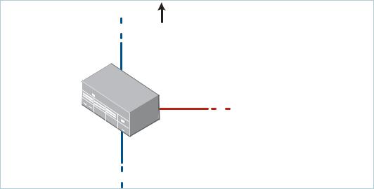
Links
AMF links are used to connect AMF nodes to AMF nodes in other AMF domains, and are either uplinks or downlinks. Uplinks are used to connect a domain with a higher Core distance (further from the Core) to a domain with a lower Core distance (closer to the Core. Downlinks are used to connect a domain with a lower Core distance to a domain with a higher Core distance.
AMF links are used to pass AMF management traffic between nodes, but can also be used to carry other network traffic. Configuring an interface as an atmf-link will automatically put the port into trunk mode. An AMF link must have at least one tagged VLAN, or have a native VLAN defined. An AMF link can be either a single link or a static aggregator.
Crosslinks
AMF crosslinks are used to connect AMF nodes to other AMF nodes within the same AMF domain. AMF master nodes must be connected using AMF crosslinks to ensure they are part of the core domain. Configuring an interface as an atmf-crosslink will automatically put the port into trunk mode. A crosslink can be either a single link or a static aggregator.
Core Domain
Uplink
AMF |
|
Member |
node |
|
|
Crosslink
Downlink
Figure 2: AMF uplinks, downlinks, and crosslinks
How to Configure and Use AMF on Allied Telesis Switches | Page 15
AMF network guidelines
Working-sets
An AMF working-set is a set of nodes, which is either arbitrarily user defined, or one of the pre-defined working-set groups (see "Working-set groups" on page 38). Specifying or selecting a working-set allows CLI commands to be executed on all nodes within the selected working-set with a single command. A working-set can be defined, selected and configured from any node within an AMF network.
|
|
|
|
AMF Network |
|
|
||
|
|
|
|
|
Master |
1 |
|
|
|
|
|
|
|
|
|
|
|
|
|
|
Member |
1 |
|
|
|
|
|
|
|
|
|
|
|
|
|
Member |
3 |
|
|
|
|
|
|
|
|
|
|
|
AMF |
|
|
|
|
|
Member |
|
|
|
|
Member |
|
|
|
|
|
working-set |
|
|
|||
|
|
|
|
|
|
|
||
|
|
4 |
|
|
|
|
|
2 |
|
|
|
Member |
5 |
|
|
|
|
|
|
|
|
|
|
|
|
|
|
|
|
|
|
Member |
6 |
|
|
|
|
|
|
|
|
|
||
Master |
2 |
|
Figure 3: AMF working-set containing nodes Master1, Member1, Member2, and Member6
AMF network guidelines
Retention and use of the ‘manager’ username
The default username for an Alliedware Plus login is manager, with a documented default password. Users should change this password on all their nodes to provide login security. In order to centrally manage nodes undergoing automated node recovery, or to expand the network by adding a new unconfigured node, it will be necessary to login with the default manager username.
It is possible to add new usernames and passwords to nodes, but to retain the ability to centrally manage the network, usernames should be uniformly configured across all AMF nodes within the AMF network.
Page 16 | How to Configure and Use AMF on Allied Telesis Switches
AMF network guidelines
Loop-free data plane
The current version of AMF does not control the data plane, so it is a requirement that the network is configured such that the data plane is kept loop free.
Note: Currently AMF does not support the use of STP on links between AMF nodes. Use of STP with redundant network links has the potential to block AMF control connections, and also could lead to periods of traffic leakage during the start of automatic node recovery. Hence, if there are physical loops in any of the data VLANs in the network, then EPSR must be used as the protection mechanism for those loops.
Aggregators
Dynamic Aggregators (LACP) cannot be used on ports configured as AMF links or crosslinks. Therefore any aggregated links in an AMF network need to be configured as static aggregators.
VCStacks
If any VCStacks are included as AMF nodes it is a requirement that the VCS virtual MAC feature is enabled to ensure correct operation of the AMF network. If the VCStack is running as an AMF master node it is also a requirement that removable external storage media is installed in both stack members.
AMF external removable media
All AMF master nodes require external storage media (e.g. USB memory stick, SD card) to be installed. This external storage is used to hold a backup of all relevant files from all nodes within the AMF network, including other master nodes, so it must be large enough to be able to accommodate all of the backed up files. Files that are backed up include all configuration files, release files, and scripts, but not core dumps, exception logs, or technical support files.
Typically a 4GB capacity external media device would be of sufficient size to hold backups for a 40 node AMF network.
When using Dual CFCs in a SBx8100, a memory stick is required in both CFCs.
How to Configure and Use AMF on Allied Telesis Switches | Page 17
AMF network guidelines
AMF interaction with QoS and ACLs
It's important that ACL and QoS rules do not block any traffic on VLAN 4091 and 4092 as they are the default AMF control VLANs. Likewise ACL and QoS rules should not block any Layer 3 traffic on 172.31.0.* or 172.31.128.* as these are the default AMF management traffic subnets. Packets with protocol type 0xfbae and BPDU packets that use the MAC address:
0180.c200.002e should also not be blocked.
Note: The AMF control VLANs and AMF management subnets can be manually changed.
With AMF enabled, the number of ACLs on the x510 switch decreases from 249 to 248. If this is an issue, then you can disable AMF, which will allow the previous maximum of 249.
Enabling AMF on the x610 switch provides 2048 ACLs.
NTP and AMF
AMF uses NTP to synchronize the system clocks across nodes within the network. For this to operate there must either be one or more external NTP servers configured on the network, or one single AMF node must be configured as the NTP 'master' using the command ntp master 11.
Note: It is not valid to have an NTP master configured on an AMF node anywhere in the network if any external NTP servers exist, as this will prevent clock synchronization.
If there is no external server, and instead the network has a node configured with the command: ntp master 11, the following commands will work as expected:
awplus (config)#atmf working set group all awplus (config)#clock set 16:51:00 24 Aug 2012
The clock set command may also be used prior to configuring an external NTP server to get the network roughly up to the correct time, so that NTP will synchronize faster.
The primary function of NTP within an AMF network is to ensure that time and date stamps on backups are consistent across member nodes within the backup. This is particularly important in an AMF network that has multiple AMF master nodes, to ensure that node recovery is performed with the most up to date backup.
Page 18 | How to Configure and Use AMF on Allied Telesis Switches
Configuring AMF
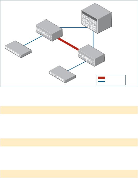
Configuring AMF
The following configuration example uses a simplified network to explain the steps required to configure AMF.
Simple AMF example with a single master
|
|
|
|
|
|
|
|
|
|
|
|
|
|
AMF |
|
|
|
|
|
|
|
|
|
|
|
|
|
|
Master |
1 |
|
||
|
|
|
|
|
|
|
|
|
port1. |
|
|
|
|
|
||
|
|
|
|
|
port1. |
|
|
|
|
|
|
|
|
|
||
|
|
|
|
Member |
1. |
|
|
|
1. |
|
|
|
|
|
||
|
|
|
|
|
1 |
|
|
|
|
1 |
|
|
|
|
|
|
|
|
port1. |
|
1 |
|
|
|
|
|
|
|
|
|
|
|
|
|
|
|
|
|
|
|
|
|
|
|
|
port1. |
|
|||
|
|
|
|
|
|
|
|
|
|
|
|
|
|
|||
|
|
1. |
|
|
|
|
|
|
|
|
|
|
|
|||
port1. |
|
|
3 |
|
|
|
|
|
|
|
|
|
|
|
||
|
|
|
|
|
|
|
|
|
|
|
port1. |
|
|
1. |
||
|
|
|
|
port1. |
|
|
|
|
|
|
|
|
2 |
|||
0. |
|
|
|
|
|
|
|
|
|
|
|
|
||||
|
1 |
|
|
|
|
|
|
|
|
1. |
|
|
|
|||
|
|
|
|
|
|
|
|
|
|
|
1 |
|
|
|
||
Member |
|
|
|
|
|
1. |
|
|
|
|
|
|
|
|
|
|
|
|
|
|
|
|
2 |
port1. |
|
|
Member |
|
|
|
|||
|
|
|
|
|
|
|
|
|
|
|
|
|
||||
|
3 |
|
|
|
|
|
|
|
1. |
|
|
|
|
|||
|
|
|
|
|
|
|
|
|
2 |
|
2 |
|
||||
|
|
|
|
|
|
|
|
|
|
|
|
|||||
|
|
|
|
|
|
|
|
|
port1. |
|
|
|||||
|
|
|
|
|
|
|
|
|
|
|
|
|
||||
|
|
|
|
|
|
|
|
|
|
|
|
|
|
|
||
|
|
|
|
|
|
|
|
|
|
1. |
|
|
|
|
|
|
|
|
|
|
|
|
port1. |
|
|
|
3 |
|
|
|
|
|
|
|
|
|
|
|
|
|
|
|
|
|
|
|
|
|
||
|
|
|
|
|
|
|
0. |
|
|
|
|
|
|
|
|
|
|
|
|
|
|
Member |
1 |
|
|
|
|
|
|
|
|||
|
|
|
|
|
4 |
|
|
|
|
|
|
Crosslink |
||||
|
|
|
|
|
|
|
|
|
|
|
|
|
|
|||
|
|
|
|
|
|
|
|
|
|
|
|
|
|
|
|
|
|
|
|
|
|
|
|
|
|
|
|
|
|
|
|
|
Link |
Figure 4: Simple AMF network
Configuration AMF Master
1. Set the host name.
awplus#conf t
awplus(config)#hostname AMF_Master
Host names are used as the AMF node name and must be unique within the AMF network.
2. Set the AMF network name.
AMF_Master (config)#atmf network-name atmf1
Note: The AMF network name must be the same on all nodes within the AMF network, and the device must be rebooted before the AMF network name takes effect.
3.Configure the device as the AMF master.
AMF_Master (config)#atmf master
An AMF network must have at least one master configured. A licence is required for each AMF master in the AMF network. If an AT-x8100 with dual CFCs is configured as an AMF master a licence is only required on the CFC master, as the licence with be synchronized
How to Configure and Use AMF on Allied Telesis Switches | Page 19
Configuring AMF
across CFCs. If an AT-x908 VCStack is configured as an AMF master, a licence is required to be installed on both stack members.
4. Configure the data VLANs.
AMF_Master(config)#vlan database
AMF_Master(config-vlan)#vlan 2-3
5. Disable RSTP globally (this is enabled by default).
AMF_Master (config)#no spanning-tree rstp enable
6. Configure ports as AMF-links.
AMF_Master(config)#int port1.1.1-1.1.2
AMF_Master(config-if)#switchport atmf-link
7. Configure data VLANs on AMF-links as required.
AMF_Master (config-if)#switchport trunk allowed vlan add 2-3
8. Save the configuration and reboot the switch.
AMF_Master #copy running-config startup-config
Building configuration...[OK]
AMF_Master#reload
Are you sure you want to reboot the whole chassis? (y/n): y
Configuration Member 1
1. Set the host name.
awplus#conf t awplus(config)#hostname Member1
Host names must be unique within the AMF network.
2. Set the AMF network name.
Member1(config)#atmf network-name atmf1
Note: The AMF network name must be the same on all nodes within the AMF network, and the device must be rebooted before the AMF network name takes effect.
3. Configure data VLANs.
Member1(config)#vlan database
Member1(config-vlan)#vlan 2-3
4.Disable RSTP globally (this is enabled by default).
Member1(config)#no spanning-tree rstp enable
Page 20 | How to Configure and Use AMF on Allied Telesis Switches
Configuring AMF
5. Configure ports as AMF-links.
Member1(config)#int port1.1.1,port1.1.3
Member1(config-if)#switchport atmf-link
6. Configure data VLANs on the AMF links as required.
Member1(config-if)#switchport trunk allowed vlan add 2-3
7. Configure AMF-crosslink.
Member1(config)#int port1.1.2
Member1(config-if)#switchport atmf-crosslink
Member1(config-if)#switchport trunk native vlan none
Note: AMF links and crosslinks are not required to be configured with data VLANs and can be used solely to provide AMF management VLAN redundancy.
8. Save the configuration and reboot the switch.
Member1#copy running-config startup-config Building configuration...
[OK]
Member1#reload
reboot system? (y/n): y
Configuration Member 2
1. Set the host name.
awplus#conf t awplus(config)#hostname Member2
Note: Hostnames are used as the AMF node name and must be unique within the AMF network..
2. Set the AMF network name.
Member2(config)#atmf network-name atmf1
Note: The AMF network name must be the same on all nodes within the AMF network, and the device must be rebooted before the AMF network name takes effect.
3. Configure a data VLAN.
Member2(config)#vlan database
Member2(config-vlan)#vlan 2-3
4.Disable RSTP globally (this is enabled by default).
Member2(config)# no spanning-tree rstp enable
How to Configure and Use AMF on Allied Telesis Switches | Page 21
Configuring AMF
5. Configure ports as AMF-links.
Member2(config)#int port1.1.1,port1.1.3
Member2(config-if)#switchport atmf-link
6. Configure data VLANs on the AMF-links as required.
Member2(config-if)#switchport trunk allowed vlan add 2-3
7. Configure AMF-crosslink.
Member2(config)#int port1.1.2
Member2(config-if)#switchport atmf-crosslink
Member2(config-if)#switchport trunk native vlan none
Note: AMF links and crosslinks are not required to be configured with data VLANs and can be used solely to provide AMF management VLAN redundancy.
8. Save the configuration and reboot the switch.
Member2#copy running-config startup-config Building configuration...
[OK]
Member2#reload
reboot system? (y/n): y
Configuration Member 3
1. Set the host name.
awplus#conf t awplus(config)#hostname Member3
Host names must be unique within the AMF network.
2. Set the AMF network name.
Member3(config)#atmf network-name atmf1
Note: The AMF network name must be the same on all nodes within the AMF network, and the device must be rebooted before the AMF network name takes effect.
3. Configure data VLANs on the AMF-link.
Member3(config)#vlan database
Member3(config-vlan)#vlan add 2-3
4.Disable RSTP globally (this is enabled by default).
Member3(config)#no spanning-tree rstp enable
Page 22 | How to Configure and Use AMF on Allied Telesis Switches

Configuring AMF
5. Configure ports as AMF-links.
Member3(config)#int port1.0.1
Member3(config-if)#switchport atmf-link
6. Configure data VLANs on the AMF links as required.
Member3(config-if)#switchport trunk allowed vlan add 2-3
7. Save the configuration and reboot the switch.
Member3#copy running-config startup-config Building configuration...
[OK]
Member3#reload
reboot system? (y/n): y
Configuration Member 4
1. Set the host name.
awplus#conf t awplus(config)#hostname Member4
Host names must be unique within the AMF network.
2. Set the AMF network name.
Member4(config)#atmf network-name atmf1
Note: The AMF network name must be the same on all nodes within the AMF network, and the device must be rebooted before the AMF network name takes effect.
3. Configure data VLANs
Member4(config)#vlan database
Member4(config-vlan)#vlan 2-3
4.Disable RSTP globally (this is enabled by default).
Member4(config)#no spanning-tree rstp enable
5.Configure ports as AMF-links.
Member4(config)#int port1.0.1
Member4(config-if)#switchport atmf-link
6. Configure data VLANs on the AMF links as required.
Member4(config-if)#switchport trunk allowed vlan add 2-3
How to Configure and Use AMF on Allied Telesis Switches | Page 23

Configuring AMF
7. Save the configuration and reboot the switch.
Member4#copy running-config startup-config Building configuration...
[OK]
Member4#reload
reboot system? (y/n): y
Verifying the AMF network
To check that all nodes have joined the AMF network use the show atmf summary command, which can be executed from any node in the AMF network:
AMF_Master#show atmf summary
ATMF Summary Information:
ATMF Status |
: Enabled |
Network Name |
: atmf1 |
Node Name |
: AMF_Master |
Role |
: Master |
Current ATMF Nodes |
: 5 |
AMF_Master# |
|
The Current ATMF Nodes field in the output above shows that all 5 nodes have joined the AMF network.
Use the show atmf nodes command to check information on individual nodes: |
||||||
AMF_Master#show atmf nodes |
|
|
|
|
|
|
Node Information: |
|
|
|
|
|
|
* = Local device |
|
|
|
|
|
|
SC = Switch Configuration: |
|
|
|
|
|
|
C = Chassis |
S = Stackable |
N = Standalone |
|
|
|
|
Node |
Device |
ATMF |
|
|
|
Node |
Name |
Type |
Master |
SC |
|
Parent |
Depth |
--------------------------------------------------------------------- |
||||||
* AMF_Master |
AT-SBx81CFC400 |
Y |
C |
none |
0 |
|
Member1 |
SwitchBlade x908 |
N |
S |
AMF_Master |
1 |
|
Member2 |
SwitchBlade x908 |
N |
S |
AMF_Master |
1 |
|
Member4 |
x510-52GTX |
|
N |
S |
Member2 |
2 |
Member3 |
x510-52GTX |
|
N |
S |
Member2 |
2 |
Current ATMF node count 5 |
|
|
|
|
|
|
Note: The Parent field refers to the parent domain and not the upstream device. In the example output above, Member2 is the domain controller for the parent domain for Member3 and Member4.
Page 24 | How to Configure and Use AMF on Allied Telesis Switches

Using the AMF network
Using the AMF network
AMF backups
AMF backups are an essential part of AMF network operation, as they are the mechanism by which AMF master nodes update their records of the AMF network. By default, AMF master nodes are configured to perform automatic scheduled backups of the entire AMF network once per day at 3.00am. AMF backups are stored on external removable media (e.g. USB Flash stick, SD card), thus it is a requirement that all AMF masters have external removable media installed that is of sufficient capacity to hold all of the relevant files stored in the Flash by every node in the AMF network.
Typically a 4GB capacity external media device would be of sufficient size to hold backups for a 40 node AMF network.
The AMF node backup system has been designed such that the external media used to store the backup data can still be used to store other data, however care needs to be taken to ensure that enough space is reserved for future AMF backups.
AMF requires up to 128MB backup space for SBx8100 nodes and up to 64MB backup space for other nodes. The show atmf backup command output will provide warnings if capacity on the backup media falls below a safe level.
Here is some example output of the show atmf backup command showing a backup media space warning:
master1#show atmf backup
Scheduled Backup ...... |
Disabled |
Schedule ............ |
1 per day starting at 12:45 |
Next Backup Time .... 25 May 2012 12:45 |
|
Backup Media .......... |
SD (Total 3827.0MB, Free 7.1MB) |
|
WARNING: Space on backup media is below 64MB |
Current Action ........ |
Idle |
Started ............. |
- |
Current Node ........ |
- |
How to Configure and Use AMF on Allied Telesis Switches | Page 25
Using the AMF network
Safe removal of external storage media
Removing external storage media, or rebooting the master node, while an AMF backup is underway could potentially cause corruption to files in the backup. Although files damaged as a result of mishandling backup media will be replaced during the next backup cycle, if the file system on the media becomes damaged it may require reformatting before being inserted into the AMF master. To avoid any damage to the AMF backup files or file system it is recommended that the following procedure is followed before rebooting or removing any external storage media from an AMF master.
1.Disable backups to prevent a scheduled backup from occurring while the card is being removed.
2.Terminate any backup already in process.
3.Verify that it is safe to remove the media by checking for a Disabled scheduler and Idle backup.
Here is an example output showing the safe external storage media removal procedure:
master1#conf t |
|
master1(config)#no atmf |
backup enable |
master1(config)#exit |
|
master1#atmf backup stop |
|
master1#show atmf backup |
|
Scheduled Backup ...... |
Disabled |
Schedule ............ |
1 per day starting at 12:45 |
Next Backup Time .... |
25 May 2012 12:45 |
Backup Media .......... |
SD (Total 3827.0MB, Free 3257.1MB) |
Current Action ........ |
Idle |
Started ............. |
- |
Current Node ........ |
- |
... |
|
|
|
Once the media has been reinstalled, ensure that the backup scheduler is re-enabled: master1#conf t
master1(config)#atmf backup enable master1(config)#exit
Page 26 | How to Configure and Use AMF on Allied Telesis Switches

Performing a manual backup
Performing a manual backup
Whenever a new device is added to the AMF network or when the configuration has changed on a member node, it is always advisable to perform a manual backup from the AMF master in order to ensure the removable media installed on the master node has an up to date backup of all nodes within the AMF.
To perform a manual backup of the entire AMF network, on the AMF master enter the command atmf backup now:
AMF_Master#atmf backup now
Backup successfully initiated
AMF_Master#
To check the status of the AMF backup use the command show atmf backup.
Example output of the show atmf backup command during backup:
AMF_Master#show atmf backup |
|
|
|
Scheduled Backup ...... |
Enabled |
|
|
Schedule ............ |
1 per day starting at 03:00 |
|
|
Next Backup Time .... |
14 Dec 2012 03:00 |
|
|
Backup Media .......... |
USB (Total 3692.6MB, Free 1782.7MB) |
||
Current Action ........ |
Doing manual backup |
|
|
Started ............. |
13 Dec 2012 05:20 |
|
|
Current Node ........ |
Member1 |
|
|
Node Name |
Date |
Time |
In ATMF On Media Status |
------------------------------------------------------------------------------
AMF_Master |
13 Dec 2012 |
05:20:16 |
Yes |
Yes |
Good |
Member1 |
- |
- |
Yes |
Yes |
- |
Member2 |
- |
- |
Yes |
No |
- |
Member3 |
- |
- |
Yes |
No |
- |
Member4 |
- |
- |
Yes |
No |
- |
Example output of the show atmf backup command after backup has completed:
AMF_Master#show atmf backup |
|
Scheduled Backup ...... |
Enabled |
Schedule ............ |
1 per day starting at 03:00 |
Next Backup Time .... |
13 Dec 2012 03:00 |
Backup Media .......... |
USB (Total 3692.6MB, Free 1651.1MB) |
Current Action ........ |
Idle |
Started ............. |
- |
Current Node ........ |
- |
Node Name Date Time In ATMF On Media Status
------------------------------------------------------------------------------
ATMF_Master |
13 |
Dec 2012 |
05:20:16 |
Yes |
Yes |
Good |
|
Member1 |
13 |
Dec 2012 |
05:20:27 |
Yes |
Yes |
Good |
|
Member2 |
13 |
Dec 2012 |
05:20:40 |
Yes |
Yes |
Good |
|
Member3 |
13 |
Dec |
2012 |
05:20:52 |
Yes |
Yes |
Good |
Member4 |
13 |
Dec |
2012 |
05:21:08 |
Yes |
Yes |
Good |
Note: The file system used by the AMF backup does not support the backing up of files that have the same name but have different case (e.g. “test.txt” and “TEST.txt”), and only one of these files will be stored in the backup. For this reason it is recommended that all files on a node have unique file names.
How to Configure and Use AMF on Allied Telesis Switches | Page 27

Backups on VCStacks running as AMF masters
Backups on VCStacks running as AMF masters
When a VCStack or SBx8100 with dual CFCs is running as an AMF master node, it is important to note that an AMF backup will only occur on the external removable media installed in the VCS master (or Active CFC). This means that following a failover event, the new VCS master will not have an AMF backup stored on its external storage media, and will not be able to provide configuration backup and recovery when required.
To avoid this situation, the recommended solution is to use trigger scripts to automatically perform a manual backup of the AMF network following a failover event.
Example manual backup activation script called triggered-atmfbackup.scp:
enable wait 180
atmf backup now
Note: There is a syntax difference between the configuration commands required to create the necessary trigger on the SBx8100 and SBx908.
Example trigger script configuration for the SBx8100:
awplus#conf t awplus(config)#trigger 1
awplus(config-trigger)#type chassis active-CFC-fail awplus(config-trigger)#script 1 triggered-atmfbackup.scp
Example trigger script configuration for the SBx908:
awplus#conf t awplus(config)#trigger 1
awplus(config-trigger)#type stack master-fail awplus(config-trigger)#script 1 triggered-atmfbackup.scp
If there are multiple AMF master nodes in the network, you may also want to use a trigger script or perform a manual backup of all master nodes whenever there is a failover event to ensure that all backups are up to date. Create an atmf working-set group which contains all master nodes, and then use the atmf working-set command in the trigger script to execute the manual backup on all nodes within the working set group.
To create a working-set containing all AMF master nodes, first manually select all AMF masters using the atmf working-set command:
Master#atmf working-set Master1,Master2
===================
Master1, Master2:
===================
Working set join atmf1[2]#
Page 28 | How to Configure and Use AMF on Allied Telesis Switches
Backups on VCStacks running as AMF masters
Next, create a user defined working-set group containing the nodes in the current workingset using the atmf group command:
atmf1[2]#conf t
atmf1[2](config)#atmf group AMF_masters
Here is an example manual backup activation script called atmfbackup_all_masters.scp:
enable wait 180
atmf working-set group AMF_masters atmf backup now
How to Configure and Use AMF on Allied Telesis Switches | Page 29
Node recovery
Node recovery
Automatic node recovery
AMF has been designed so that when a node fails it can be replaced with an unconfigured device of the same type, and AMF will automatically upgrade and configure the new device from the most recent backup. Often the replacement device will be a factory default, brand new “out of the box” device, but it may be that you want to replace the failed unit with one that has been previously used elsewhere. In this instance it is necessary to return the replacement device to a “clean” state so that AMF can recognize it as a suitable replacement, and begin automatic recovery. (See section "A “Clean” node" on page 31)
When a failed node is replaced with an unconfigured device, AMF immediately disables forwarding on the device, shuts down all non-AMF ports, and applies the AMF safe configuration. (See section "AMF safe configuration" on page 34.) AMF then checks whether any of the AMF master nodes has a valid backup for the replacement node, and if it finds one it begins to attempt automatic node recovery. Once automatic node recovery has completed, it will then reboot the replacement node which will then rejoin the AMF network with identical files and configuration, to the failed node it replaced.
Here is some example console output showing automatic node recovery:
Warning: No changes should be made to the device's configuration while a node recovery is underway. A log message will appear on the console or other logged in session indicating when recovery has finished (whether successfully or with errors). This message can also be found by viewing the log with the show log command.
23:03:15 awplus |
ATMF[863]: ATMF network detected |
23:03:15 awplus |
ATMF[863]: ATMF safe config applied (forwarding |
disabled) |
|
23:03:25 awplus |
ATMF[863]: Shutting down all non ATMF ports |
23:03:26 x510_1 |
ATMF[863]: Automatic node recovery started |
23:03:26 x510_1 |
ATMF[863]: Attempting to recover as x510_1 |
23:03:26 x510_1 |
ATMF[863]: Checking master node availability |
23:03:32 x510_1 |
ATMF[863]: Master has joined. 2 members in total. |
23:03:32 x510_1 |
ATMF[863]: x908_VCS_2 has joined. 3 members in total. |
23:03:32 x510_1 |
ATMF[863]: x908_VCS_1 has joined. 4 members in total. |
23:03:37 x510_1 |
ATMFFSR[2950]: Retrieving recovery data from master |
node Master |
|
23:05:18 x510_1 |
ATMFFSR[2950]: File recovery from master node |
succeeded. Node |
will now reboot |
Flushing file system buffers...
Unmounting any remaining filesystems...
Restarting system.
Page 30 | How to Configure and Use AMF on Allied Telesis Switches
Loading...