


3B SCIENTIFIC® PHYSICS
Fadenstrahlröhre U8481430
Bedienungsanleitung
07/10 ALF
1. Sicherheitshinweise
Glühkatodenröhren sind dünnwandige, evakuierte Glaskolben. Vorsichtig behandeln: Implosionsgefahr!
•Röhre keinen mechanischen Belastungen aus-setzen.
Zu hohe Spannungen, Ströme sowie falsche Katodenheiztemperatur können zur Zerstörung der Röhre führen.
•Die angegebenen Betriebsparameter einhalten.
Beim Betrieb der Röhre können am Anschlussfeld berührungsgefährliche Spannungen und Hochspannungen anliegen.
•Für Anschlüsse nur Sicherheits-Experimentier- kabel verwenden.
•Schaltungen nur bei ausgeschaltetem Versorgungsgerät vornehmen.
•Röhre nur bei ausgeschaltetem Versorgungsgerät einund ausbauen.
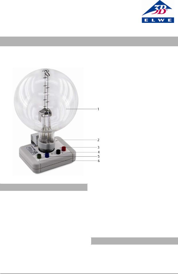
1Fadenstrahlröhre
2Anschlusssockel
3Anschluss für Anode
4Anschluss für Katode
5Anschluss für Wehnelt-Zylinder
6Anschluss für Heizung
Im Betrieb erwärmt sich der Röhrenhals.
•Röhre vor dem Wegräumen abkühlen lassen.
Die Einhaltung der EC Richtlinie zur elektromagnetischen Verträglichkeit ist nur mit den empfohlenen Netzgeräten garantiert.
2. Beschreibung
Die Fadenstrahlröhre dient zur Untersuchung der Ablenkung von Elektrodenstrahlen im homogenen Magnetfeld unter Verwendung des Helmholtzspulenpaars U8481500 sowie zur quantitativen Bestimmung der spezifischen Ladung des Elektrons e/m.
In einem Glaskolben befindet sich die Elektronenkanone, bestehend aus einer indirekt geheizten Oxidkatode, einem Wehneltzylinder und einer Lochanode in einer Neonrestgas-Atmosphäre mit präzise eingestelltem Gasdruck. Die Gasatome werden längs der Elekt-
1
ronenflugbahn ionisiert und es entsteht ein leuchtender, scharf begrenzter Strahl. Eingebaute Messmarken erlauben die parallaxenfreie Bestimmung des Kreisbahndurchmessers des im Magnetfeld abgelenkten Strahls.
Die Fadenstrahlröhre ist auf einem Sockel mit farbigen Anschlussbuchsen montiert. Zum Schutz der Röhre ist im Sockel eine Schutzschaltung installiert, die die Spannung oberhalb der auf dem Röhrensockel angegebenen „Cutoff-Voltage“ (Abschaltspannung) abschaltet. Die Schutzschaltung verhindert, dass eine zu hohe Spannung die Heizung zerstört und sorgt dafür, dass beim Einschalten die Spannung „weich“ hochfährt.
3. Technische Daten |
|
|
|
|
|
Gasfüllung: |
Neon |
|
Gasdruck: |
1,3 x 10⁻⁵ bar |
|
Heizspannung: |
4 bis 12 V DC (siehe Angabe |
|
|
„Cutoff-Voltage“ auf dem Röh- |
|
|
rensockel) |
|
Heizstrom: |
300 bis 450 mA |
|
Wehneltspannung: |
0 bis -50 V |
|
Anodenspannung: |
200 bis 300 V |
|
Anodenstrom: |
< 0,3 mA |
|
Fadenstrahlkreis: |
20 bis 120 mm Ø |
|
Messmarkenabstand: |
20 mm |
|
Kolbendurchmesser: |
160 mm |
|
Gesamthöhe: |
260 mm |
|
Anschlusssockel: |
115 x 115 x 35 mm3 |
|
Masse: |
ca. 820 g |
|
4. Allgemeine Grundlagen
Auf ein Elektron, das sich mit der Geschwindigkeit v senkrecht zu einem homogenen Magnetfeld B bewegt, wirkt senkrecht zur Geschwindigkeit und zum Magnetfeld die Lorentz-Kraft
F = e v B |
(1) |
|||||
e: Elementarladung |
|
|||||
Sie zwingt das Elektron als Zentripetalkraft |
|
|||||
F = |
m v2 |
|
(2) |
|||
|
r |
|||||
|
|
|
||||
m: Elektronenmasse |
|
|||||
auf eine Kreisbahn mit dem Radius r. Daher ist |
|
|||||
e B = |
m v |
|
(3) |
|||
r |
||||||
|
|
|
||||
Die Geschwindigkeit v hängt von der Beschleunigungsspannung U der Elektronenkanone ab:
v = 2 e U |
(4) |
m |
|
Für die spezifische Ladung des Elektrons gilt somit:
e |
= |
2 U |
(5) |
|
|
||
m |
(r B)2 |
Misst man für verschiedene Beschleunigungsspannungen U und verschiedene Magnetfelder B jeweils den Kreisbahnradius r, so liegen die Messwerte in einem r2B2-2U-Diagramm gemäß Gl. (5) auf einer Ursprungsgeraden mit der Steigung e/m.
Das Magnetfeld B wird in einem Helmholtz-Spulenpaar erzeugt und ist proportional zum Strom IH durch eine einzelne Spule. Der Proportionalitätsfaktor k kann aus dem Spulenradius R = 147,5 mm und der Windungszahl N = 124 je Spule berechnet werden:
|
4 |
3 |
|
−7 Vs |
|
N |
|
|
mT |
||
2 |
|
|
|
|
|||||||
B = k IH mit k = |
|
|
|
4π 10 |
|
|
|
|
= 0 |
,756 |
|
|
|
|
Am |
R |
A |
||||||
|
5 |
|
|
|
|
|
|
||||
Damit sind sämtliche Bestimmungsgrößen für die spezifische Elektronenladung bekannt.
5. Zusätzlich erforderliche Geräte
1 DC-Netzgerät 300 V (230 V, 50/60 Hz) |
U8521371-230 |
oder |
|
1 DC-Netzgerät 300 V (115 V, 50/60 Hz) |
U8521371-115 |
und |
|
1 DC-Netzgerät 20 V, 5 A (230 V, 50/60 Hz) |
U33020-230 |
oder |
|
1 DC-Netzgerät 20 V, 5 A (115 V, 50/60 Hz) |
U33000-115 |
oder |
|
1 DC-Netzgerät 500 V (230 V, 50/60 Hz) |
U33000-230 |
oder |
|
1 DC-Netzgerät 500 V (115 V, 50/60 Hz) |
U33000-115 |
1 Helmholtz-Spulenpaar |
U8481500 |
1 bzw. 2 Analog-Multimeter AM50 |
U17450 |
Sicherheits-Experimentierkabel |
|
6. Bedienung
6.1 Aufbau
•Fadenstrahlröhre zwischen die Helmholtzspulen stellen.
•Um den Elektronenstrahl besser beobachten zu können, das Experiment in einem abgedunkelten Raum durchgeführen.
6.1.1 Betrieb mit dem DC-Netzgerät 300 V U8521371
•Beschaltung gemäß Fig. 1 durchführen.
•Volmeter an den 300-V-Ausgang des Netzgerätes anschließen.
2

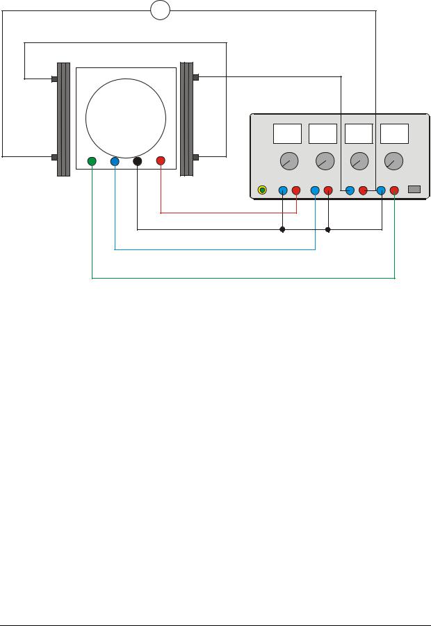
•Spulen gemäß Fig. 2 in Reihe an das DC-Netzgerät 20 V U33020 anschließen, so dass beide Spulen gleichsinnig vom Strom durchflossen werden.
6.1.2 Betrieb mit dem DC-Netzgerät 500 V U33000
•Beschaltung gemäß Fig. 4 durchführen.
6.2 Justierung des Elektronenbündels
•Heizspannung von z.B. 7,5 V anlegen. (Die Heizspannung muss unter der „Cutoff-Voltage“ liegen.)
•Ca. 1 Minute abwarten bis sich die Temperatur der Heizwendel stabilisiert hat.
•Anodenspannung langsam bis auf max. 300 V erhöhen (der zunächst waagerechte Elektronenstrahl wird durch ein schwaches, bläuliches Licht sichtbar).
•Wehnelt-Spannung so wählen, dass ein möglichst dünnes, scharf begrenztes Strahlenbündel zu sehen ist.
•Schärfe und Helligkeit des Strahlenbündels durch Variation der Heizspannung optimieren.
•Spulenstrom IH durch die Helmholtz-Spulen erhöhen und überprüfen, ob der Elektronenstrahl nach oben gekrümmt wird.
Falls keine Krümmung des Elektronenstrahls zu beobachten ist:
•Eine der Spulen umpolen, so dass der Strom gleichsinnig durch beide Spulen fließt.
U8521371
Off On
Falls die Krümmung des Elektronenstrahls nicht nach oben zeigt:
•Zum Umpolen des Magnetfeldes die Anschlusskabel am Netzgerät vertauschen.
•Spulenstrom weiter erhöhen und überprüfen, ob der Elektronenstrahl eine in sich geschlossene Kreisbahn bildet.
Falls die Kreisbahn nicht geschlossen ist:
•Fadenstrahlrohr samt Sockel etwas um die vertikale Achse drehen.
7. Versuchsbeispiel
Bestimmung der spezifischen Ladung des Elektrons e/m
•Spulenstrom so wählen, dass der Kreisbahnradius z. B. 5 cm beträgt. Eingestellten Wert notieren.
•Anodenspannung in 20-V-Schritten auf 200 V ver-
kleinern, jeweils den Spulenstrom IH so wählen, dass der Radius konstant bleibt. Diese Werte notieren.
•Weitere Messreihen für die Kreisbahnradien 4 cm und 3 cm aufnehmen.
•Zur weiteren Auswertung die Messwerte in einem r2B2-2U-Diagramm auftragen (siehe Fig. 3).
Die Steigung der Ursprungsgeraden entspricht e/m.
ı |
0... |
300 V |
0 |
...-50 V |
6... |
12 V |
PE |
O |
|
|
|
|
|
|
|
Fig. 1 Anschluss der Fadenstrahlröhre an das DC-Netzgerät 300 V U8521371
3
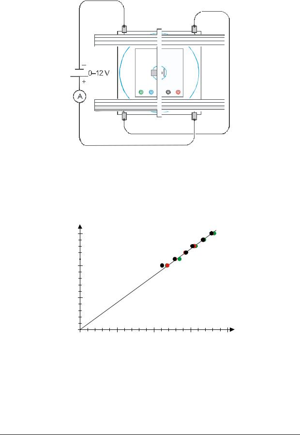
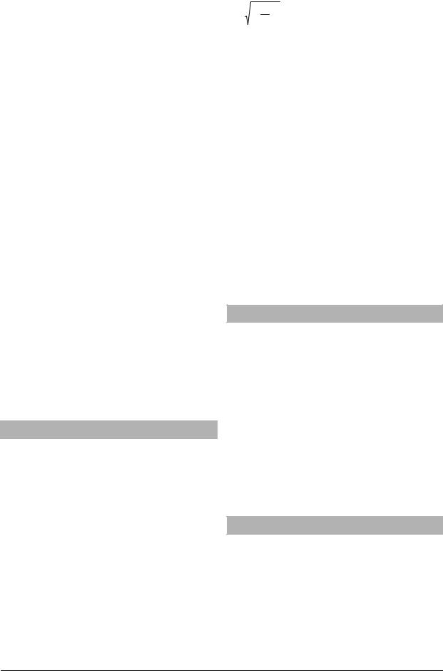
Fig. 2 Beschaltung der Helmholtz-Spulen
2U / V |
|
|
|
|
600 |
|
|
|
|
400 |
|
|
|
|
200 |
|
|
|
|
0 |
|
20 |
30 |
40 |
0 |
10 |
|||
|
|
|
B2 r2 / mT2 cm2 |
|
Fig. 3 r2B2-2U-Diagramm der Messwerte (schwarz: r = 5 cm, rot: r = 4 cm, grün: r = 3 cm)
4
A |
|
|
|
|
|
|
|
U33000 |
|
|
|
|
|
|
|
0...500 V |
0...50 V |
0...8 V |
0...12 V |
||||
- |
+ |
- |
+ |
- |
+ |
- |
+ |
Fig. 4 Anschluss der Fadenstrahlröhre an das DC-Netzgerät 500 V U33000 |
|
|
|
|
|||
Elwe Didactic GmbH • Steinfelsstr. 6 • 08248 Klingenthal • Deutschland • www.elwedidactic.com 3B Scientific GmbH • Rudorffweg 8 • 21031 Hamburg • Deutschland • www.3bscientific.com Technische Änderungen vorbehalten
© Copyright 2010 3B Scientific GmbH
3B SCIENTIFIC® PHYSICS
Fine Beam Tube U8481430
Instruction sheet
07/10 ALF
1. Safety instructions
Hot cathode tubes are thin-walled, highly evacuated glass tubes. Treat them carefully as there is a risk of implosion.
•Do not subject the tube to mechanical stresses.
If voltage or current is too high or the cathode is at the wrong temperature, it can lead to the tube becoming destroyed.
•Do not exceed the stated operating parameters.
When the tube is in operation, the terminals of the tube may be at high voltages with which it is dangerous to come into contact.
•Only use safety experiment leads for connecting circuits.
•Only change circuits with power supply switched off.
1Fine beam tube
2Connector base
3Connection for anode
4Connection for cathode
5Connection for Wehnelt cylinder
6Connection for heater
•Set up or dismantle the tubes only when the power supply unit is switched off.
When the tube is in operation, the stock of the tube may get hot.
•Allow the tube to cool before putting away the apparatus.
The compliance with the EC directive on electromagnetic compatibility is only guaranteed when using the recommended power supplies.
2. Description
The Fine Beam Tube is used for investigating the deflection of cathode rays in a uniform magnetic field produced by a pair of Helmholtz coils (U8481500). In addition, it can also be used for quantitative determination of the specific charge of an electron e/m.
1
Located inside a glass bulb with a neon residual gas atmosphere is an electron gun, which consists of an indirectly heated oxide cathode, a Wehnelt cylinder and a perforated anode. The gas atoms are ionised along the path of the electrons and a narrow, well-defined, luminescent beam is produced. Incorporated measurement marks facilitate a parallax-free determination of the diameter of the circular path of the beam deflected in the magnetic field.
The Fine Beam Tube is mounted on a base with coloured connectors. In order to protect the tube, a protective circuit is built into the base, which shuts off any voltage in excess of the base’s pre-set cut-off voltage. The protective circuit prevents excessive voltages from damaging the heater filament and ensures a “smooth” switch-on response once the voltage is applied.
3. Technical data |
|
|
|
Gas filling: |
Neon |
Gas pressure: |
1,3 x 10⁻⁵ bar |
Filament voltage: |
4 to 12 V DC (see cut-off- |
|
voltage on tube socket) |
Filament current: |
300 to 450 mA |
Wehnelt voltage: |
0 bis -50 V |
Anode voltage: |
200 to 300 V |
Anode current: |
< 0.3 mA |
Diameter of fine beam path: 20 to 120 mm |
|
Division spacing: |
20 mm |
Tube diameter: |
160 mm |
Total height incl. base: |
260 mm |
Base plate: |
115 x 115 x 35 mm3 |
Weight: |
approx. 820 g |
4. Basic principles
An electron moving with velocity v in a direction perpendicular to a uniform magnetic field B experiences a Lorentz force in a direction perpendicular to both the velocity and the magnetic field
F = e v B |
(1) |
e: elementary charge
This gives rise to a centripetal force on the electron in a circular path with radius r, where
F = |
m v2 |
|
and |
(2) |
|
|
r |
||||
|
|
|
|
||
m is the mass of an electron. |
|
||||
Thus, |
|
|
|||
e B = |
m v |
|
(3) |
||
r |
|
||||
|
|
|
|
||
The velocity v depends on the accelerating voltage of the electron gun:
v = 2 e U |
(4) |
m |
|
Therefore, the specific charge of an electron is given by:
e |
= |
2 U |
(5) |
|
|
||
m |
(r B)2 |
If we measure the radius of the circular orbit in each case for different accelerating voltages U and different magnetic fields B, then, according to equation 5, the measured values can be plotted in a graph of r2B2 against 2U as a straight line through the origin with slope e/m.
The magnetic field B generated in a pair of Helmholtz coils is proportional to the current IH passing through a single coil. The constant of proportionality k can be determined from the coil radius R = 147.5 mm and the number of turns N = 124 per coil:
B = k IH where
|
|
4 |
3 |
|
−7 Vs |
|
N |
|
mT |
||
k = |
2 |
4π 10 |
|
= 0,756 |
|||||||
|
|
|
|
|
|
|
|
||||
5 |
|
|
Am |
R |
A |
||||||
Thus, all parameters for the specific charge are known.
5. Additionally required equipment
1 DC power supply 300 V (230 V, 50/60 Hz) |
U8521371-230 |
|
or |
|
|
1 DC power supply 300 V (115 V, 50/60 Hz) |
U8521371-115 |
|
and |
|
|
1 DC power supply 20 V, 5 A (230 V, 50/60 Hz) |
U33020-230 |
|
or |
|
|
1 DC power supply 20 V, 5 A (115 V, 50/60 Hz) |
U33000-115 |
|
or |
|
|
1 DC power supply 500 V (230 V, 50/60 Hz) |
|
U33000-230 |
or |
|
|
1 DC power supply 500 V (115 V, 50/60 Hz) |
|
U33000-115 |
1 Pair of Helmholtz coils |
|
U8481500 |
1 resp. 2 Analogue multimeter AM50 |
|
U17450 |
Safety leads |
|
|
6. Operation
6.1 Set up
•Place the fine beam tube between the Helmholtz coils.
•To get a clearer view of the electron beam, conduct the experiment in a darkened room.
6.1.1Set up with the DC power supply unit 300 V U8521371
•Set up the tube as in fig. 1.
2

•Connect the voltmeter in parallel to the 300-V output.
•Connect the coils in series to the DC power supply 20 V U33020, as shown in Fig. 2, so that equal current passes through both coils.
6.1.2Set up with the DC power supply unit 500 V U33000
•Set up the tube as in fig. 4.
6.2 Adjusting the electron beam
•Apply a heater voltage of say 7.5 V. (the heater voltage must be below the cut-off voltage).
•Wait about 1 minute for the heater temperature to stabilise.
•Slowly increase the anode voltage to 300 V (the electron beam is initially horizontal and is visible as a weak, bluish ray).
•Select the Wehnelt voltage so that a very clear and narrow electron beam is visible.
•Optimise the focus and brightness of the electron beam by varying the heater voltage.
•Increase the current IH passing through the Helmholtz coils and check that the electron beam curves upwards.
U8521371
Off  On
On
•If the electron beam is not deflected at all:
•Reverse the polarity of one of the coils so that current passes in the same direction through both coils.
If the electron beam does not curve upwards:
•Swap the connections on the power supply unit to reverse the polarity of the magnetic field.
•Continue increasing the current passing through the coils watch until the electron beam forms a closed circle.
If the path does not form a closed circle:
•Slightly turn the fine beam tube, along with its base, around its vertical axis.
7. Sample experiment
Determination of the specific charge of an electron e/m
•Select the current passing through the coils so that the radius of the circular path is for example 5 cm. Note the set current value.
• Decrease the anode voltage in steps of 20 V to 200 V. In each case, set the coil current IH so that the radius remains constant. Take down these values.
•Record other series of measured values for radii of 4 cm and 3 cm.
•For further evaluation, plot the measured values in a graph of r2B2 against 2U (see Fig. 3).
The slope of the line through the origin corresponds to e/m.
ı |
0... |
300 V |
0... |
-50 V |
6... |
12 V |
PE |
O |
|
|
|
|
|
|
|
Fig. 1 Electrical connections from the fine beam tube to the DC power supply unit 300 V U8521371
3
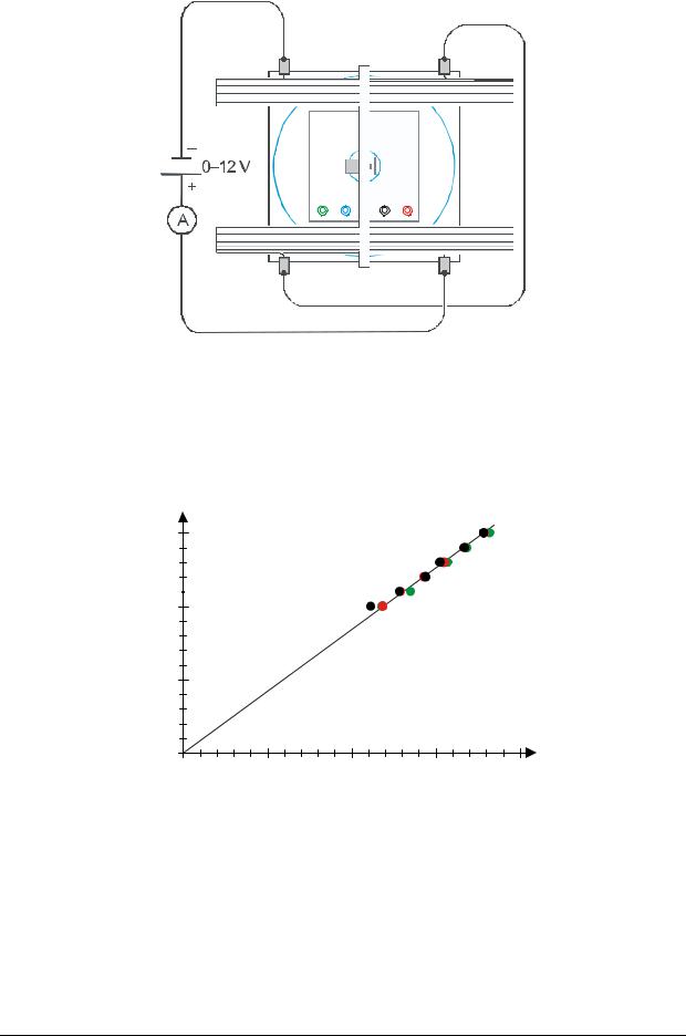
Fig. 2 Electrical connections to the pair of Helmholtz coils
2U / V |
|
|
|
|
600 |
|
|
|
|
400 |
|
|
|
|
200 |
|
|
|
|
0 |
|
|
|
|
0 |
10 |
20 |
30 |
40 |
|
|
|
B2 r2 / mT2 cm2 |
|
Fig. 3 Graph of r2B2 against 2U for values as measured (black: r = 5 cm, red: r = 4 cm, green: r = 3 cm)
4
A |
|
|
|
|
U33000 |
|
|
|
|
0...500 V |
0...50 V |
0...8 V |
0...12 V |
|
- |
+ |
- + |
- + |
- + |
Fig. 4 Electrical connections from the fine beam tube to the DC power supply 500 V U33000
Elwe Didactic GmbH • Steinfelsstr. 6 • 08248 Klingenthal • Germany • www.elwedidactic.com 3B Scientific GmbH • Rudorffweg 8 • 21031 Hamburg • Germany • www.3bscientific.com Subject to technical amendments
© Copyright 2010 3B Scientific GmbH
 Loading...