

3B SCIENTIFIC® PHYSICS
Teslameter, 20 mT, 200 mT U33110
Bedienungsanleitung
02/09 ALF
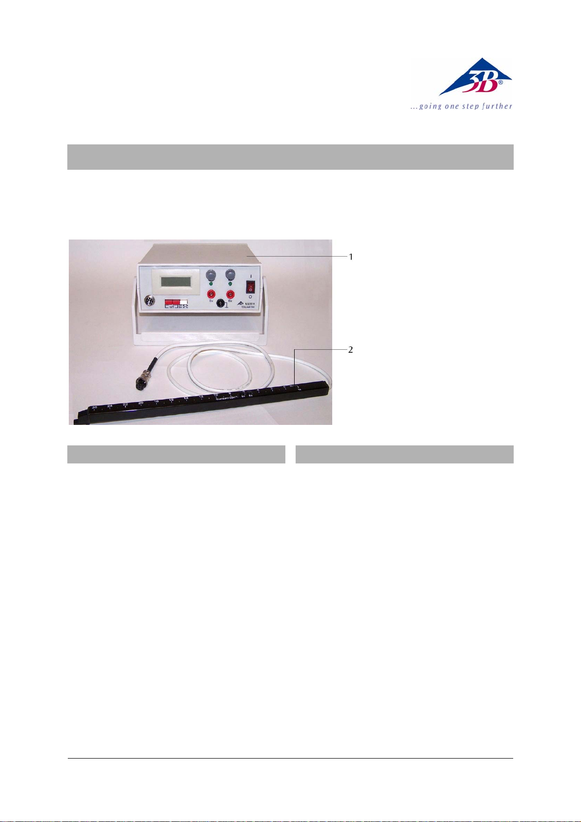
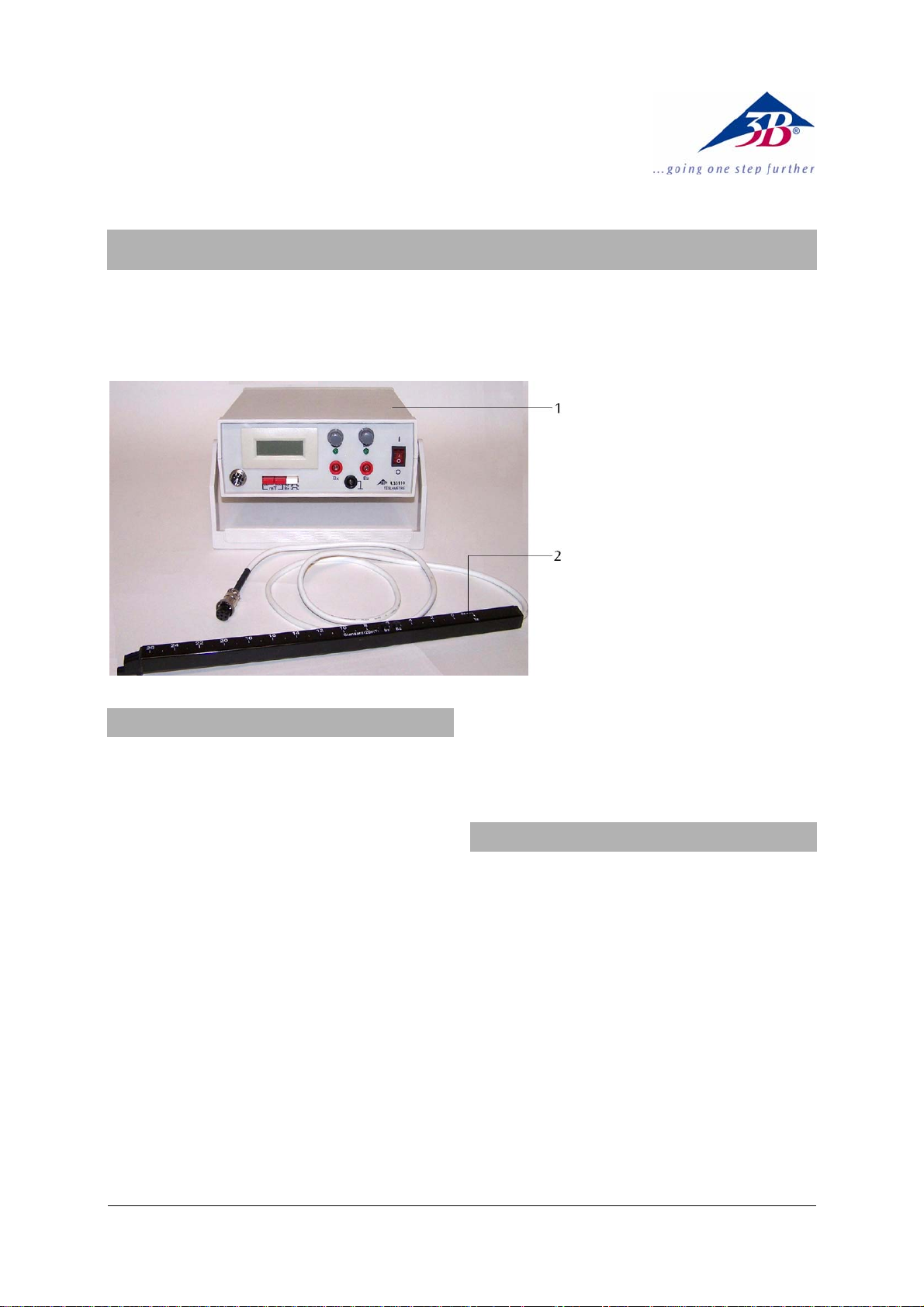
1 Teslameter
2 Magnetfeldsonde
1. Sicherheitshinweise
Das Teslameter, 20 mT, 200 mT entspricht den Sicherheitsbestimmungen für elektrische Mess-, Steuer-,
Regel- und Laborgeräte nach DIN EN 61010 Teil 1 und
ist nach Schutzklasse II aufgebaut. Es ist für den Betrieb in trockenen Räumen vorgesehen, die für elektrische Betriebsmittel geeignet sind.
Bei bestimmungsgemäßem Gebrauch ist der sichere
Betrieb des Gerätes gewährleistet. Die Sicherheit ist
jedoch nicht garantiert, wenn das Gerät unsachgemäß
bedient oder unachtsam behandelt wird.
Wenn anzunehmen ist, dass ein gefahrloser Betrieb
nicht mehr möglich ist (z.B. bei sichtbaren Schäden),
ist das Gerät unverzüglich außer Betrieb zu setzen.
• Vor Erstinbetriebnahme überprüfen, ob der auf
der Gehäuserückseite aufgedruckte Wert für die
Netzanschlussspannung den örtlichen Anforderungen entspricht.
• Vor Inbetriebnahme das Gehäuse und die Netzlei-
tung auf Beschädigungen untersuchen und bei
Funktionsstörungen oder sichtbaren Schäden das
Gerät außer Betrieb setzen und gegen unbeabsichtigten Betrieb sichern.
• Gerät nur durch eine Elektrofachkraft öffnen
lassen.
2. Beschreibung
Das Teslameter dient zur Messung der Flussdichte in
magnetischen Gleichfeldern.
Das Gerät beinhaltet einen Hallsensor zur Messung
axialer und tangentialer Magnetfelder bis zu 200 mT.
Die Magnetfeldsonde ist zur Abstandsmessung mit
einer metrischen Skala versehen.
Neben der digitalen Anzeige des Magnetfelds liefert
das Gerät auch eine zum Magnetfeld proportionale
Spannung, die einem Datenlogger, einem XYSchreiber oder einem analogen Multimeter zugeführt
werden kann.
Das Teslameter ist in zwei Spannungsversionen erhältlich. Das Gerät mit der Artikelnummer U33110-115 ist
für eine Netzspannung von 115 V (±10 %) ausgelegt,
das Gerät mit der Artikelnummer U33110-230 für eine
Netzspannung von 230 V (±10 %).
1

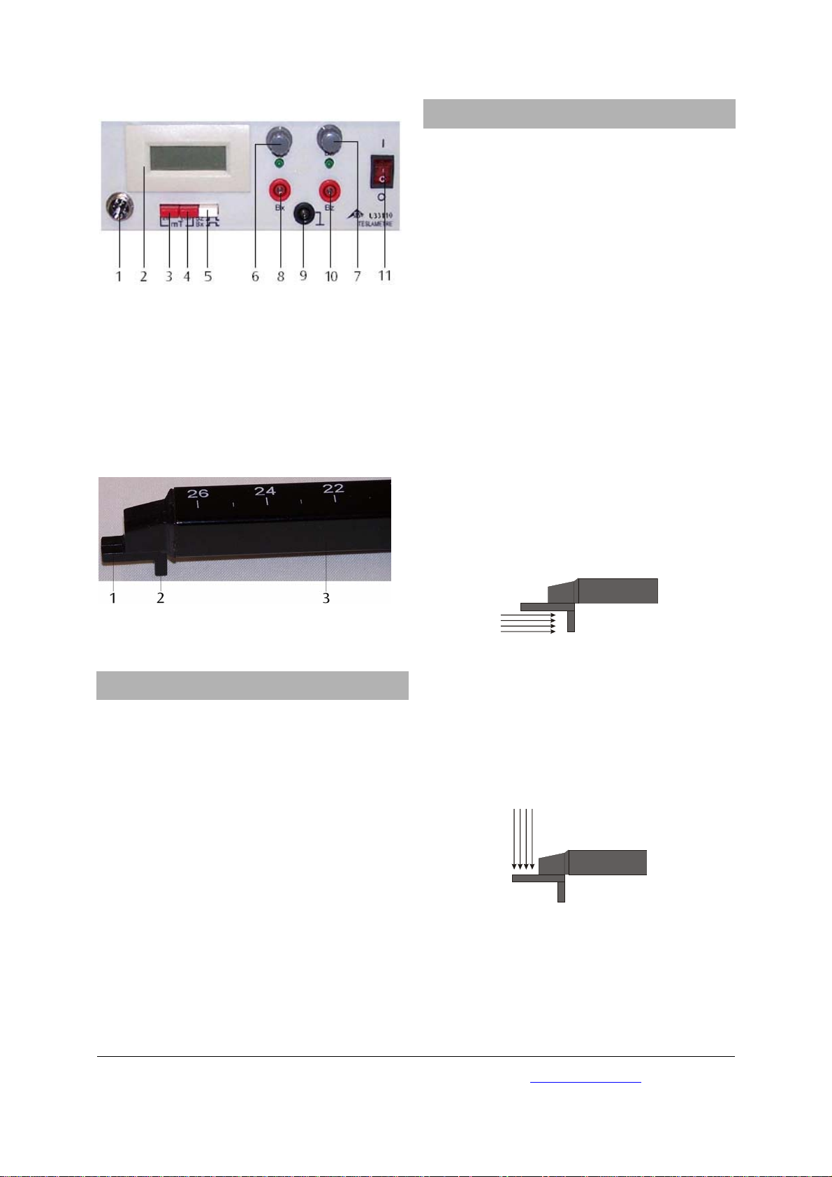
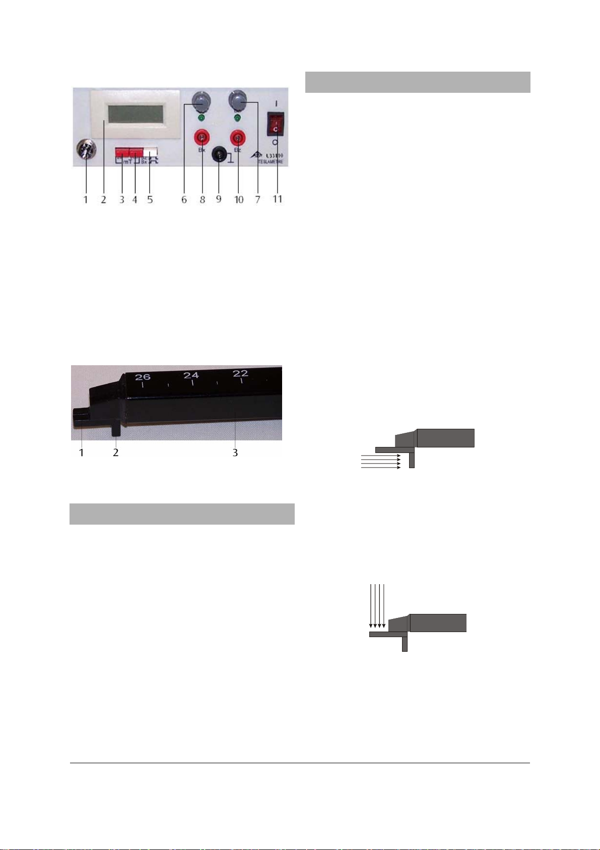
2.1 Bedienelemente
4.1 Nullpunkteinstellung
Es empfiehlt sich, den Nullpunktabgleich im Messbereich 20 mT vorzunehmen. Beim anschließenden
Umschalten in den größeren Messbereich ist dann
kein neuer Abgleich erforderlich.
Wenn Magnetfelder von Permanentmagneten gemessen werden sollen, ist der Nullpunktabgleich in ausreichendem Abstand vom Magneten durchzuführen.
Wenn die Felder stromdurchflossener Leiter gemessen
1 Anschlussbuchse für Magnetfeldsonde
2 Digitalanzeige
3 Messbereichswahlschalter 20 mT
4 Messbereichswahlschalter 200 mT
5 Messmoduswahlschalter axial (B
6 Nullpunktsteller B
7 Nullpunktsteller B
8 Ausgangsbuchse für Messmodus B
9 Massebuchse
10 Ausgangsbuchse für Messmodus B
11 Ein-/Ausschalter
mit LED Betriebsanzeige
X
mit LED Betriebsanzeige
Z
) und tangential (BZ)
X
X
Z
werden sollen, ist es empfehlenswert die Sonde bei
abgeschaltetem Magnetfeldstrom am vorgesehenen
Messort zu positionieren.
• Magnetfeldsonde an der Anschlussbuchse 1 an-
schließen.
• Messmodus 20 mT wählen.
• Nullpunktsteller so lange drehen, bis die Null oder
ein möglichst kleiner Wert im Anzeigefeld erscheint.
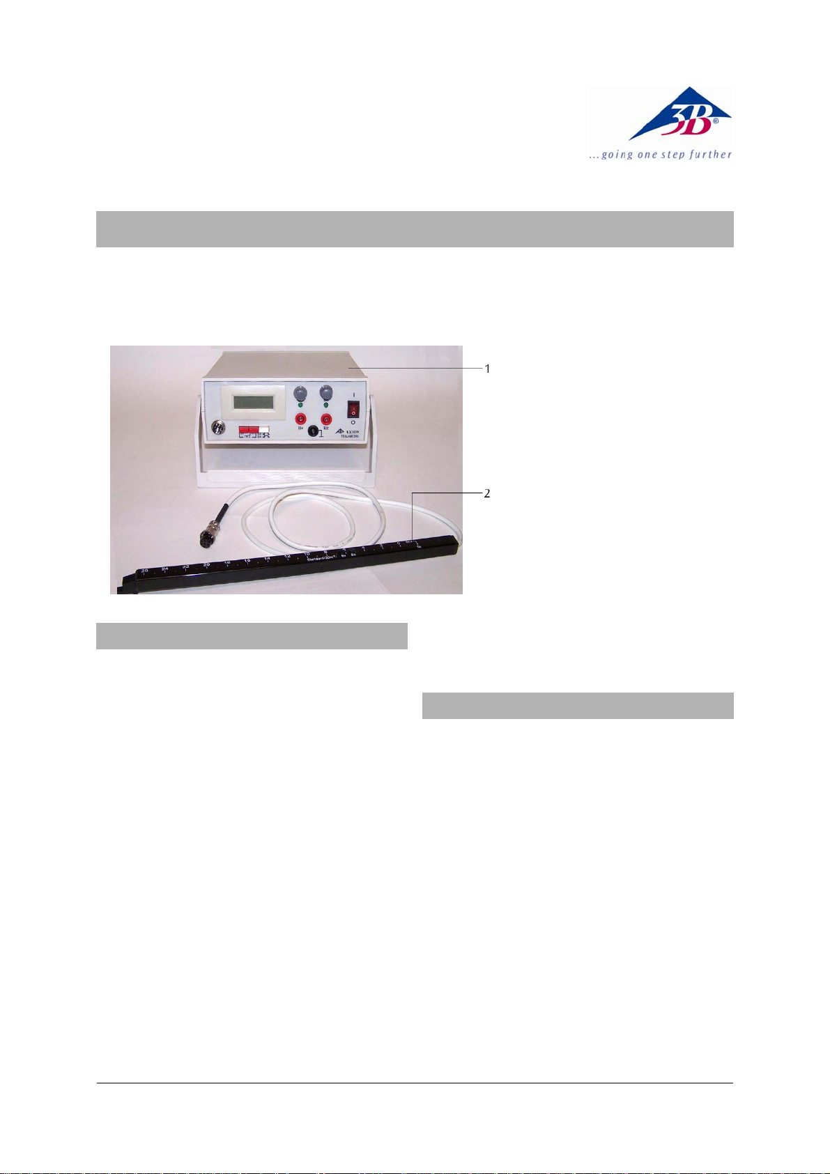
4.2 Messung axialer Magnetfelder
Mit der axialen Hallsonde wird die Komponente der
magnetischen Induktion in Richtung der Sondenachse
gemessen.
Zusätzlich kann die Feldrichtung erkannt werden: Zeigt
das Feld in die Richtung des Sondenträgers (z.B. vor
dem Nordpol eines Stabmagneten), so ist der angezeigte Wert positiv, bei umgekehrter Orientierung negativ.
Magnetfeldsonde: 1 axiale Hallsonde (x-Richtung), 2 tangentiale Hallsonde (z-Richtung), 3 Träger
3. Technische Daten
Messbereich 20 mT
Auflösung: 0,01 mT
Genauigkeit: 2 % ±3 digits
Messbereich 200 mT
Auflösung: 0,1 mT
Genauigkeit: 2 % ±1 digits
Anzeige: 3½-stelliges LCD mit Vor-
4.3 Messung tangentialer Magnetfelder
Mit der tangentialen Hallsonde wird die Komponente
der magnetischen Induktion, die senkrecht zur Trägerplatte orientiert ist, gemessen.
Zusätzlich kann die Feldrichtung erkannt werden:
Eine positive Anzeige bedeutet, dass das Feld aus der
Richtung der Trägeroberfläche mit Skala kommend in
die Sonde eintritt, während ein negativer Wert auf die
umgekehrte Feldrichtung hinweist.
zeichen fur die Feldrich tung
Ziffernhöhe: 13 mm
Eingang: BNC-Buchse
Ausgang: 4-mm-Sicherheitsbuchsen
Ausgangsspannung: 10 mV / mT (20 mT)
1 mV / mT (200 mT)
Abmessungen Gerät: 205 x 230 x 85 mm³
Abmessungen Sonde: 360 x 15 x 25 mm³
4.4 Benutzung des Analogausgangs
Über die Ausgangsbuchsen (8, 9, 10) kann eine zum
Magnetfeld proportionale Spannung externen Messgeräten (Datenlogger, XY-Schreiber, analoge Multimeter)
zugeführt werden. Die Ausgangsspannung korrespondiert mit der Digitalanzeige. Sie beträgt 10 mV pro mT
Messwert im 20 mT-Bereich und 1 mV pro mT Messwert im 200 mT-Bereich.
4. Bedienung
3B Scientific GmbH • Rudorffweg 8 • 21031 Hamburg • Deutschland • www.3bscientific.com
Technische Änderungen vorbehalten
© Copyright 2009 3B Scientific GmbH
3B SCIENTIFIC® PHYSICS
Teslameter, 20 mT, 200 mT U33110
Instruction sheet
02/09 ALF
1 Teslameter
2 Magnetic field probe
1. Safety instructions
The teslameter, 20 mT, 200 mT conforms to all safety
regulations for electrical measuring, control,
monitoring and laboratory equipment, as specified
under DIN EN 61010, Section 1, and the equipment
has been designed to meet protection class II. It is
intended for operation in a dry environment, suitable
for the operation of electrical equipment and
systems.
Safe operation of the equipment is guaranteed,
provided it is used correctly. However, there is no
guarantee of safety if the equipment is used in an
improper or careless manner.
If it may be assumed for any reason that nonhazardous operation will not be possible (e.g. visible
damage), the equipment should be switched off
immediately and secured against any unintended use.
• Before using the power supply unit for the first
time, confirm that the specifications printed on
the rear side of the housing are compatible with
the local mains voltage.
• Before using the power supply unit for the first
time, check the housing and the mains lead for
any damage. In the event of any
malfunction/operational defect or visible
damage, switch off the unit immediately and
secure it against unintended use.
• The equipment may only be opened/repaired by
qualified and trained personnel.
2. Description
The teslameter is used for the measurement of flux
densities in steady magnetic fields.
The unit includes a Hall sensor probe for measuring
axial and tangential magnetic fields up to 200 mT.
The magnetic field probe is provided with a metric
scale for measuring distances.
In addition to having a digital display, the unit
outputs a voltage proportional to the magnetic field
which can be measured with a data logger, XYrecorder or analogue multimeter.
The teslameter is available in 2 versions for differing
mains voltages. The teslameter with the order number
U33110-230 is for mains supplies of 230 V (±10%) while
the one with order no. U33110-115 is for 115 V (±10%)
systems.
1
2.1 Operating controls and connections
1 Connecting socket for magnetic field probe
2 Digital display
3 Measurement range selector, 20 mT
4 Measurement range selector, 200 mT
5 Measurement mode switch, axial (B
6 Zero adjustment knob for B
7 Zero adjustment knob for B
8 Output socket for axial mode B
9 Earth (ground) socket
10 Output socket for tangential mode B
11 On/off switch
) and tangential (BZ)
X
with LED indicator
X
with LED indicator
Z
X
Z
4. Operation
4.1 Zero adjustment
It is recommended that the zero adjustment should
be carried out with the measurement range set to 20
mT. If the range is subsequently changed to the larger
one, it is not necessary to repeat the adjustment.
If the magnetic field of a permanent magnet is to be
measured, the zero adjustment must be carried out at
a sufficiently large distance from the magnet.
If the fields of current-carrying conductors are to be
measured, it is recommended to first switch off the
magnetic field current and position the probe at the
point where the measurement is to be made.
• Connect the magnetic field probe to the probe socket 1.
• Select the 20 mT measurement range.
• Rotate the zero adjustment knob until the
indicated field value is zero or as small as possible.
4.2 Measurement of axial magnetic fields
The axial Hall probe measures the component of the
magnetic flux density along the direction of the probe
axis.
It is also possible to determine the direction of the
magnetic field: if the field lines are directed towards the
probe carrier (e.g., like the field coming from the north
pole of a bar magnet), the indicated value is positive,
whereas for the opposite direction it is negative.
Magnetic field probe: 1 axial Hall probe (x-direction), 2
tangential Hall probe (z-direction), 3 probe carrier
3. Technical data
Measurement range 20 mT
Resolution: 0.01 mT
Accuracy: 2 % ±3 digits
Measurement range 200 mT
Resolution: 0.1 mT
Accuracy: 2 % ±1 digits
4.3 Measurement of tangential magnetic fields
The tangential Hall probe measures the component of
the magnetic flux density in the direction
perpendicular to the carrier plate.
It is also possible to determine the direction of the
magnetic field: a positive reading indicates that the
field entering the tangential probe comes from the
direction of the carrier surface with the scale
markings, whereas a negative reading indicates that it
is in the opposite direction.
Digital display: 3½ digit LCD with sign
showing field direction
Height of digits: 13 mm
Input: BNC socket
Output: 4 mm safety sockets
Output voltage: 10 mV / mT (20 mT)
1 mV / mT (200 mT)
Dimensions of unit: 205 x 230 x 85 mm³
Dimensions of probe: 360 x 15 x 25 mm³
4.4 Using the analogue output signals
The output sockets (8, 9, 10) provide voltages
proportional to the magnetic field components that
can be fed to external measuring devices (data
loggers, XY graph plotters, or analogue multimeters).
The output voltage corresponds to the digital reading.
It amounts to 10 mV per mT field value in the 20 mT
operating range and 1 mV per mT field value in the
200 mT operating range.
3B Scientific GmbH • Rudorffweg 8 • 21031 Hamburg • Germany • www.3bscientific.com
Subject to technical amendments
© Copyright 2009 3B Scientific GmbH
3B SCIENTIFIC® PHYSICS
Teslamètre, 20 mT, 200 mT U33110
Instructions d'utilisation
02/09 ALF
1 Teslamètre
2 Sonde de champs magnétiques
1. Consignes de sécurité
Le teslamètre, 20 mT, 200 mT est conforme aux
directives de sécurité relatives aux appareils
électriques de mesure, de commande et de régulation
ainsi qu’aux appareils de laboratoire conformément à
la norme DIN EN 61010 Partie 1 et répond à la classe
de protection II. Il est conçu pour une utilisation dans
des endroits secs adaptés aux matériels électriques.
Une utilisation conforme à la destination garantit un
emploi de l’appareil en toute sécurité. La sécurité
n’est cependant pas garantie si l’appareil fait l’objet
d’un maniement inapproprié ou s’il est manipulé avec
imprudence.
S’il s’avère que son utilisation ne peut plus se faire
sans danger (par ex. dans le cas d’un
endommagement visible), l’appareil doit être
immédiatement mis hors service.
• Avant une première mise en service, vérifier si la
tension secteur indiquée sur le boîtier est
conforme aux exigences locales.
• Avant toute mise en service, vérifier que le boîtier
et le câble du secteur sont bien exempts de tout
endommagement et mettre l’appareil hors service
en le protégeant contre une marche involontaire
en cas de pannes de fonctionnement ou de
dommages visibles.
• Faire ouvrir l’appareil uniquement par un
électricien.
2. Description
Le teslamètre sert à mesurer la densité de flux de
champs magnétiques continus.
L'unité comprend un capteur-sonde à effet Hall
permettant de mesurer les champs magnétiques
axiaux et tangentiels jusqu'à 200 mT. La sonde de
champs magnétiques dispose d'une échelle métrique
permettant de mesurer les distances.
Cette unité dispose non seulement d'un affichage
numérique, mais elle permet également la sortie
d'une tension proportionnelle au champ magnétique
qui pourra être mesurée par un enregistreur de
données, un enregistreur XY ou un multimètre
analogique.
Le teslamètre existe en deux versions de tension
différentes. Le teslamètre portant le numéro d'article
U33110-230 est dimensionné pour une tension de
secteur de 230 volts (±10 %) ; le transformateur
portant le numéro d'article U33110-115 est
dimensionné pour une tension de 115 volts (±10 %).
1

2.1 Éléments de commande
1 Douille de jonction pour la sonde de champs magnétiques
2 Affichage numérique
3 Commutateur de sélection de la plage de mesures, 20 mT
4 Commutateur de sélection de la plage de mesures, 200 mT
5 Commutateur de sélection des modes de mesure axial
) et tangentiel (BZ)
(B
X
6 Dispositif de mise à zéro BX avec témoin de
fonctionnement LED
7 Dispositif de mise à zéro BZ avec témoin de
fonctionnement LED
8 Douille de sortie pour mode de mesure BX
9 Douille de masse
10 Douille de sortie pour mode de mesure B
11 Commutateur marche/arrêt
Z
Sonde de champs magnétiques : 1 sonde de Hall axiale
(direction X), 2 sondes de Hall tangentielles (direction Y), 3
supports
4. Manipulation
4.1 Réglage du point zéro
Nous vous recommandons de procéder à un
ajustement du point zéro dans la plage de mesures de
20 mT. Ce qui vous permettra de ne plus devoir
procéder à un nouvel ajustement si vous passez
ensuite à une plage de mesures supérieure.
Si vous voulez mesurer les champs magnétiques
d'aimants permanents, veillez à procéder à un
ajustement du point zéro à une distance
suffisamment éloignée des aimants.
Si vous voulez mesurer les champs de conducteurs
traversés par un courant électrique, nous vous
conseillons de positionner la sonde à l'emplacement
de mesure prévu après avoir arrêté le courant du
champ magnétique.
• Raccordez la sonde de champs magnétiques à la
douille de jonction 1.
• Sélectionnez le mode de mesure 20 mT.
• Tournez le dispositif de mise à zéro jusqu'à ce
que le zéro ou qu'une valeur aussi petite que
possible apparaisse dans le champ d’affichage.
4.2 Mesure de champs magnétiques axiaux
La sonde de Hall axiale permet de mesurer la
composante de l'induction magnétique en direction
de l'axe de la sonde.
Il est en outre possible de détecter la direction du
champ : si le champ s'oriente en direction du porteur
de la sonde (devant le pôle nord d'un barreau
aimanté, par exemple), la valeur affichée est alors
positive ; dans le cas d'une orientation inverse, cette
valeur sera alors négative.
3. Caractéristiques techniques
Plage de mesure 20 mT
Résolution : 0,01 mT
Précision : 2 % ±3 digits
Plage de mesure 200 mT
Résolution : 0,1 mT
Précision : 2 % ±1 digits
Affichage : LCD numérique à 3½
chiffres avec signe pour
la direction du champ
Hauteur des chiffres : 13 mm
Entrée : douille BNC
Sortie : douilles de sécurité de 4 mm
Tension de sortie : 10 mV / mT (20 mT)
1 mV / mT (200 mT)
Dimensions de l'unité : 205 x 230 x 85 mm³
Dimensions de la sonde : 360 x 15 x 25 mm³
4.3 Mesure de champs magnétiques tangentiels
La sonde de Hall tangentielle permet de mesurer la
composante de l'induction magnétique qui s'oriente
perpendiculairement par rapport à la plaque de support.
Il est en outre possible de détecter la direction du
champ : un affichage positif signifie que le champ
venant de la direction de la surface du support avec
échelle, pénètre dans la sonde, une valeur négative
signalant par contre la direction opposée du champ.
2

4.4 Utilisation de la sortie analogique
Via les douilles de sortie (8, 9, 10), il est possible
d'envoyer une tension proportionnelle au champ
magnétique à des instruments de mesure externes
(enregistreur de données, enregistreur XY, mulitmètres
analogiques). La tension de sortie correspond à
l'affichage numérique. Elle est de 10 mV par mT de
valeur mesurée dans la plage de 20 mT et de 1 mV par
mT de valeur mesurée dans la plage de 200 mT.
3B Scientific GmbH ▪ Rudorffweg 8 ▪ 21031 Hamburg ▪ Allemagne ▪ www.3bscientific.com
Sous réserve de modifications techniques
© Copyright 2009 3B Scientific GmbH


3B SCIENTIFIC® PHYSICS
Teslametro, 20 mT, 200 mT U33110
Istruzioni per l'uso
02/09 ALF
1 Teslametro
2 Sonda magnetica
1. Norme di sicurezza
Il teslametro, 20 mT, 200 mT risponde alle
disposizioni di sicurezza per apparecchi elettrici di
misura, di comando, di regolazione e da laboratorio
della norma DIN EN 61010 parte 1 ed è realizzato in
base alla classe di protezione II. L'apparecchio è
pensato per l’utilizzo in ambienti asciutti, adatti per
strumenti elettrici.
Un utilizzo conforme garantisce il funzionamento
sicuro dell'apparecchio. La sicurezza non è tuttavia
garantita se l'apparecchio non viene utilizzato in
modo appropriato o non viene trattato con cura.
Se si ritiene che non sia più possibile un
funzionamento privo di pericoli, l'apparecchio deve
essere messo immediatamente fuori servizio (ad es. in
caso di danni visibili).
• Prima di utilizzare l'apparecchio per la prima
volta, verificare che il valore stampato
sull'alloggiamento per la tensione di
alimentazione corrisponda ai requisiti locali.
• Prima della messa in funzione controllare che
l'alloggiamento non presentino danni; in caso di
disturbi nel funzionamento o danni visibili
mettere l’apparecchio fuori servizio e al sicuro da
ogni funzionamento involontario.
• Fare aprire l'apparecchio solo da un elettricista
specializzato.
2. Descrizione
Il teslametro viene utilizzato per la misurazione della
densità di flusso in campi magnetostatici.
L’unità comprende una sonda con sensore di Hall per
la misura dei campi magnetici assiali e tangenziali
fino a 200 mT. La sonda magnetica è dotata di una
scala metrica per la misura delle distanze.
Oltre ad avere un display digitale, l’unità produce una
tensione proporzionale al campo magnetico, che può
essere misurata con un registratore dati, un
registratore XY o un multimetro analogico.
Il teslametro è disponibile in 2 versioni di tensione. Il
teslametro con il numero articolo U33110-230 è
progettato per una tensione di rete di 230 V (±10 %),
Il teslametro con il numero articolo U33110-115 per
115 V (±10 %).
1

2.1 Elementi di comando
1 Presa di collegamento per sonda magnetica
2 Display digitale
3 Selettore range di misura 20 mT
4 Selettore range di misura 200 mT
5 Selettore modalità di misurazione assiale (B
tangenziale (B
6 Regolatore dello zero BX con indicatore di
funzionamento a LED
7 Regolatore dello zero BZ con indicatore di
funzionamento a LED
8 Presa di uscita per la modalità di misurazione BX
9 Presa di terra
10 Presa di uscita per la modalità di misurazione B
11 Interruttore ON/OFF
)
Z
) e
X
Z
4. Comandi
4.1 Impostazione dello zero
Si consiglia di effettuare la regolazione dello zero nel
range di misura 20 mT. Quando successivamente si
passa al range di misura superiore, non è necessario
effettuare una nuova regolazione.
Se devono essere misurati campi magnetici generati da
magneti permanenti, la regolazione dello zero deve
essere effettuata a una distanza sufficiente dal magnete.
Se devono essere misurati campi generati da
conduttori percorsi da corrente, è consigliabile
posizionare la sonda nel punto di misura previsto a
corrente disinserita.
• Collegare la sonda magnetica alla presa di
collegamento 1.
• Selezionare la modalità di misurazione 20 mT.
• Ruotare il regolatore dello zero finché nel campo
di visualizzazione non compare zero o un valore
più piccolo possibile.
4.2 Misurazione dei campi magnetici assiali
Con la sonda Hall assiale si misura la componente
dell’induzione magnetica nella direzione dell’asse
della sonda.
Inoltre è possibile riconoscere la direzione del campo:
se il campo è rivolto nella direzione del supporto della
sonda (ad es. davanti al polo nord di un magnete a
barra), il valore indicato è positivo; in caso di
orientamento contrario, negativo.
Sonda magnetica: 1 Sonda Hall assiale (direzione x), 2 Sonda
Hall tangenziale (direzione z), 3 Supporto
3. Dati tecnici
Gamma di misurazione 20 mT
Risoluzione: 0,01 mT
Precisione: 2 % ±3 digits
Gamma di misurazione 200 mT
Risoluzione: 0,1 mT
Precisione: 2 % ±1 digits
Display digitale: LCD numerico 3½ con segno
per la direzione del
campo
Altezza dei numeri: 13 mm
Ingresso: spina BNC
Uscita: spine di sicurezza da 4 mm
Tensione di uscita: 10 mV / mT (20 mT)
1 mV / mT (200 mT)
Dimensioni dell’unità: 205 x 230 x 85 mm³
Dimensioni della sonda: 360 x 15 x 25 mm³
4.3 Misurazione di campi magnetici tangenziali
Con la sonda Hall tangenziale si misura la
componente dell’induzione magnetica perpendicolare
alla piastra di supporto.
Inoltre è possibile riconoscere la direzione del campo:
un valore positivo significa che il campo entra nella
sonda dalla direzione della superficie di supporto con
scala, mentre un valore negativo indica la direzione
del campo opposta.
4.4 Utilizzo dell’uscita analogica
Attraverso le prese di uscita (8, 9, 10) è possibile
collegare a misuratori esterni (logger di dati,
registratori XY, multimetri analogici) una tensione
proporzionale al magnete. La tensione di uscita
corrisponde al display digitale. Il suo valore è di 10 mV
per ogni mT del valore misurato nel range 20 mT e 1
mV per ogni mT del valore misurato nel range 200 mT.
3B Scientific GmbH • Rudorffweg 8 • 21031 Amburgo • Germania • www.3bscientific.com
Con riserva di modifiche tecniche
© Copyright 2009 3B Scientific GmbH

3B SCIENTIFIC® PHYSICS
Teslámetro, 20 mT, 200 mT U33110
Instrucciones de uso
02/09 ALF
1 Teslámetro
2 Sonda de campo magnético
1. Advertencias de seguridad
El teslámetro corresponde a las regulaciones de
seguridad para dispositivos eléctricos de medición, de
mando, de control y de laboratorio, estipuladas por la
norma DIN EN 61010, parte 1, y ha sido montado
según la clase de protección II. Está previsto para el
uso en recintos secos, convenientes para los medios
de servicio eléctricos.
Su uso correcto, acorde con las prescripciones,
garantiza el servicio seguro del equipo. Sin embargo,
la seguridad no queda garantizada si el dispositivo se
usa incorrectamente o se lo manipula sin el cuidado
necesario.
Si es de suponer que ya no es posible un
funcionamiento libre de peligro (por ejemplo, por
daños visibles), se debe poner el equipo fuera de
servicio inmediatamente.
• Antes de la primera puesta en marcha, se debe
comprobar si el valor impreso en el lado posterior
de la caja corresponde a las exigencias locales de
tensión.
• Antes de poner en marcha el aparato se debe
examinar si existen daños en la caja y, en caso de
fallos en el funcionamiento o daños visibles, se
debe poner el equipo fuera de servicio asegurándolo contra una puesta en marcha involuntaria.
• Sólo un electrotécnico está autorizado a abrir el
aparato.
2. Descripción
El teslámetro sirve para la medición de densidades de
flujo en campos magnéticos continuos.
La unidad incluye una sonda, de sensor de efecto
Hall, útil para medir campos magnéticos axiales y
tangenciales de hasta 200 mT. La sonda de campo
magnético está provista de una escala métrica para
mediciones a distancia.
Además de tener un indicador digital, la unidad genera una tensión proporcional al campo magnético, el
cual se puede medir con un registrador de datos, un
registrador XY o un multímetro analógico.
El teslámetro se puede entregar en 2 versiones de
tensión. El teslámetro con el número de artículo
U33110-230 está diseñado para una tensión de red de
230 V (±10 %), el teslámetro con el número de
artículo U33110-115 es para 115 V (±10 %).
1

2.1 Elementos de mando y servicio
1 Casquillo de conexión para la sonda de campo
magnético
2 Display digital
3 Conmutador de alcance de medida de 20 mT
4 Conmutador de alcance de medida de 200 mT
5 Conmutador de alcance de medida axial (B
(B
)
Z
6 Ajuste de punto cero para B
trabajo
7 Ajuste de punto cero B
trabajo
8 Casquillo de salida para el modo de medida B
9 Casquillo de masa
10 Casquillo de salida para el modo de medida B
11 Interruptor ON / OFF
con LED de indicación de
X
con LED de indicación de
Z
) y tangencial
X
X
Z
4. Servicio
4.1 Ajuste del punto cero
Se recomienda hacer la compensación del punto cero en
el alcance de medida de 20 mT. Al cambiar a
continuación al alcance más amplio no es necesario
volver a realizar la compensación.
Cuando se deben medir campos magnéticos de
imanes permanentes se debe realizar la
compensación de cero a una distancia lo
suficientemente grande de los imanes.
Cuando se deben medir los campos de conductores
que llevan corriente, se recomienda colocar la sonda
en el punto de medición previsto teniendo la
corriente de campo magnético desconectada.
• Se conecta la sonda de campo magnético en el
casquillo de conexión 1.
• Se selecciona el modo de medida 20 mT.
• Se gira el ajuste de punto cero hasta que en el campo
de indicación se observe cero o un valor mínimo.
4.2 Medición de campos magnéticos axiales
Con la sonda de Hall axial se mide la componente de la
inducción magnética en dirección del eje de la sonda.
Además se puede reconocer la dirección del campo: Si
el campo muestra en la dirección del soporte de la
sonda (p. ej. enfrente del polo norte de un imán de
barra), el valor indicado será positivo, en la orientación
inversa correspondientemente negativo.
Sonda de campo magnético: 1 Sonda de Hall axial
(Dirección x), 2 Sonda de Hall tangencial (Dirección z),
3 Soporte
3. Datos técnicos
Rango de medición 20 mT
Resolución: 0,01 mT
Precisión: 2 % ±3 digits
Rango de medición 200 mT
Resolución: 0,1 mT
Precisión: 2 % ±1 digits
Display digital: LCD de 3½ dígitos con signo
para la dirección del campo
Altura de los dígitos: 13 mm
Entrada: casquillo BNC
Salida: casquillos de seguridad de 4 mm
Tensión de salida: 10 mV / mT (20 mT)
1 mV / mT (200 mT)
Dimensiones de
la unidad: 205 x 230 x 85 mm³
Dimensiones de la
punta sensora: 360 x 15 x 25 mm³
4.3 Medición de campos magnéticos tangenciales
Con la sonda de Hall tangencial se mide la componente
de la inducción magnética que está orientada
perpendicularmente a la placa soporte.
Además se puede reconocer la dirección del campo: Una
indicación positiva significa que el campo viniendo de
en la dirección de la superficie del soporte con escala
incide en la sonda, mientras que un valor negativo
indica una dirección de campo invertida.
4.4 Uso de la salida analógica
Por medio de los casquillos de salida (8, 9, 10) se le
puede entregar una tensión proporcional al campo
magnetico (datalogger, registradora X-Y, multímetros
analógicos). La tensión de salida corresponde a la indicación digital. Ésta es de 10 mV por mT en el alcance de
20 mT y de 1 mV por mT en el alcance de 200 mT.
3B Scientific GmbH • Rudorffweg 8 • 21031 Hamburgo • Alemania • www.3bscientific.com
No reservamos el derecho a modificaciones técnicas
© Copyright 2009 3B Scientific GmbH

3B SCIENTIFIC® FÍSICA
Teslâmetro, 20 mT, 200 mT U33110
Instruções para o uso
02/09 ALF
1 Teslâmetro
2 Sonda de campo magnético
1. Indicações de segurança
O teslâmetro, 20 mT, 200 mT é construído conforme
as regulamentações de segurança, segundo DIN EN
61010 Parte 1 e conforme a classe de segurança II.
Está previsto para ser operado em ambiente seco e é
apropriado para meios de operação elétricos.
No caso de ser utilizado conforme as indicações
operacionais de segurança esta garantida a operação
segura do aparelho. Esta segurança não estará
garantida caso o aparelho seja operado de modo
incorreto ou sem os necessários cuidados.
Caso seja determinado que o funcionamento sem
perigo não seja mais possível (por exemplo, em caso
de danificação do aparelho), deve-se imediatamente
deixar de utilizar o mesmo.
• Antes de a primeira utilização verificar se o valor
de tensão de rede impresso coincide com a
tensão de rede e condições de fornecimento
locais.
• Antes de conectar o aparelho à rede elétrica,
verificar se este esta livre de danos ou defeitos
funcionais, e caso sejam observados disfunções ou
danos visíveis, desligar imediatamente o aparelho e
garantir que não seja operado acidentalmente.
• Só permitir a abertura do aparelho por pessoal
especializado em eletricidade.
2. Descrição
O teslâmetro serve para a medição da densidade de
fluxo em campos magnéticos uniformes.
A unidade inclui uma ponta de sensor de Hall para
medir campos magnéticos axiais e tangenciais até 200
mT. A sonda de campo magnético está guarnecida
com uma escala métrica para medição de distância.
Além de ter uma indicação digital, a unidade produz
uma tensão proporcional ao campo magnético que
pode ser medido com um registrador de dados, um
registrador XY ou um multímetro análogo.
O teslâmetro esta disponível em 2 versões de tensão. O
teslâmetro com o número de item U33110-230 é
adequado para uma tensão de rede de 230 V (±10 %),
O teslâmetro com o número de item U33110-115 para
115 V (±10 %).
1
2.1 Elementos de serviço
1 Tomada de conexão para a sonda de campo magnético
2 Display digital
3 Seletor da faixa de medição 20 mT
4 Seletor da faixa de medição 200 mT
5 Seletor do modo de medição axial (B
6 Ajustador de ponto zero B
LED
7 Ajustador de ponto zero BZ com indicador de operação
LED
8 Tomada de saída do modo de medição B
9 Tomada de massa
10 Tomada de saída do modo de medição B
11 Interruptor ligar/ desligar
com indicador de operação
X
) e tangencial (BZ)
X
X
Z
4. Utilização
4.1 Calibração do ponto zero
É recomendado, proceder com o equilibro do ponto
zero na faixa de medição 20 mT. Ao comutar
seguidamente para uma faixa de medição maior, não
será necessário fazer uma nova calibração.
Quando os campos magnéticos de um imã
permanente têm que ser medidos, o equilibro do
ponto zero tem que ser executado numa distância
suficiente do imã.
Quando são medidos campos de condutores com
fluxos de corrente elétrica, é recomendável posicionar
a sonda com a corrente de campo magnético
desligada no lugar de medição prevista.
• Ligar a sonda magnética na tomada de conexão 1.
• Selecionar o modo de medição 20 mT.
• Girar o seletor de ponto zero até aparecer o zero ou
um valor o mais reduzido possível no campo do
indicador.
4.2 Medição de campos magnéticos axiais
Com a sonda de Hall axial se mede a componente de
indução magnética em direção do eixo da sonda.
Adicionalmente pode ser reconhecida a direção do
campo: Se o campo indica para a direção do portador da
sonda (Por exemplo, diante do pólo norte de um imã
permanente), o valor indicado é positivo, e com
orientação contrária é negativo.
Sonda de campo magnético: 1 sonda de Hall axial de
(Sentido x), 2 Sondas de Hall tangencial (Sentido z),
3 Portador
3. Dados técnicos
Faixa de medição 20 mT
Resolução: 0,01 mT
Precisão: 2 % ± 3 dígitos
Faixa de medição 200 mT
Resolução: 0,1 mT
Precisão: 2 % ±1 dígitos
Display digital: 3½ LCD dígital
antecedido de sinal
para a direção do
campo
Altura dos dígitos: 13 mm
Entrada: soquete BNC
Saída: soquetes de segurança
de 4 mm
Tensão de saída: 10 mV / mT (20 mT)
1 mV / mT (200 mT)
Dimensões da unidade: 205 x 230 x 85 mm³
Dimensões da ponta de sensor: 360 x 15 x 25 mm³
4.3 Medição de campos magnéticos tangenciais
Com a sonda de Hall tangencial se mede a
componente de indução magnética, que se encontra
vertical à placa portadora.
Adicionalmente pode-se reconhecer a direção do
campo: Uma indicação positiva significa que o campo
vem da direção da superfície portadora com escala
para entrar na sonda, enquanto um valor negativo
indicaria a direção de campo contrária.
4.4 Utilização da saída análoga
Através das tomadas de saída (8, 9, 10) pode-se levar
uma tensão proporcional ao campo magnético para
aparelhos externos de medição (Registrador de dados,
registrador XY, Multímetro análogo). A tensão de saída
corresponde a indicação digital. Ela vale 10 mV por
cada mT de valor de medição na faixa de medição 20
mT e 1 mV por cada um mT de valor de medição na
faixa de 200 mT.
3B Scientific GmbH • Rudorffweg 8 • 21031 Hamburgo • Alemanha • www.3bscientific.com
Sob reserva de modificações técnicas
© Copyright 2009 3B Scientific GmbH
 Loading...