


3B SCIENTIFIC® PHYSICS
Satz 4 Kalorimeterzylinder U30070
Bedienungsanleitung
11/08 ALF
1 Kalorimeter, Stahl
2 Kalorimeter, Messing
3 Kalorimeter, Kupfer
4 Kalorimeter, Aluminium
1. Sicherheitshinweise
Verbrennungsgefahr durch Heizelement oder Kalorimeter.
•Apparatur vor dem Abbau abkühlen lassen.
2. Beschreibung
Der Satz 4 Kalorimeterzylinder dient zur Bestimmung der spezifischen Wärmekapazitäten von Aluminium, Messing, Kupfer und Stahl.
Die Kalorimeterzylinder sind mit zwei Bohrungen versehen, um einen Heizstab (12,5 mm Durchmesser) sowie ein Thermometer oder eine Temperatursonde (8 mm Durchmesser) aufzunehmen.
3. Technische Daten
Masse Zylinder: |
|
ca. 1 kg (Genauigkeit ±2 %) |
||
|
|
|
|
|
|
|
Höhe |
Durchmesser |
Spezifische |
Material |
|
Wärme |
||
|
(mm) |
(mm) |
||
|
|
J/(kg*K) |
||
|
|
|
|
|
|
|
|
|
|
Aluminium |
|
84 |
75 |
896 |
|
|
|
|
|
Messing |
|
84 |
44 |
377 |
|
|
|
|
|
Kupfer |
|
85 |
43 |
385 |
|
|
|
|
|
Stahl |
|
92 |
44 |
452 |
|
|
|
|
|
4. Zusätzlich erforderliche Geräte
1 DC-Netzgerät 0 - 20 V, 0 - 5 A (230 V, 50/60 Hz) U33020-230
oder
1 DC-Netzgerät 0 - 20 V, 0 - 5 A (115 V, 50/60 Hz) U33020-115
1 |
Heizelement, 12 V |
U30075 |
1 |
Thermometer, -20°C bis +110°C |
U40911 |
1 |
Mechanische Stoppuhr, 30 min |
U40800 |
5.Bedienung
•Kalorimeterzylinder wiegen und die Masse notieren.
•Kalorimeterzylinder auf eine hitzefeste Unterlage stellen und ihn mit isolationsmaterial umgeben, so dass der Wärmeverlust so klein wie möglich ist.
•Heizelement und Thermometer in die entsprechenden Bohrungen einsetzen. Zuvor einige Tropfen Öl oder Wasser in die Thermometerbohrung geben, um einen guten thermischen Kontakt zwischen Thermometer und Kalorimeter herzustellen.
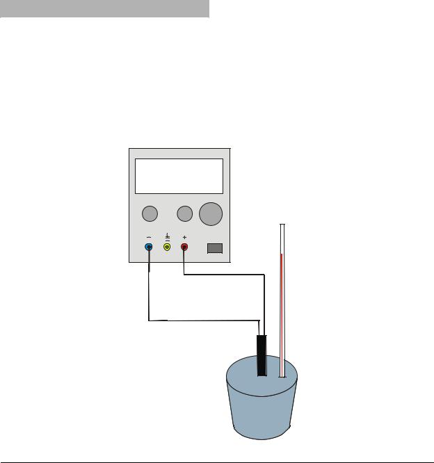
•Schaltung gemäß Fig. 1 herstellen.
•Netzgerät einschalten und einen Strom von ca. 4 A einstellen. Danach Netzgerät wieder ausschalten.
1
•Vor Start des Messlaufs einige Minuten warten. Dann die Anfangstemperatur des Kalorimeterzylinders ablesen.
•Netzgerät einschalten und gleichzeitig die Zeitmessung starten.
•Abwarten bis die Temperatur um ca. 20° C gestiegen ist. Zeit und Endtemperatur notieren.
Die spezifische Wärmekapazität ist gegeben durch die Gleichung:
I U t = m c (θ2 −θ1 )
mit I: Strom, U: Spannung, t: Zeit, m: Masse des Kalorimeterzylinders c: spezifische Wärmekapazität, θ1: Anfangstemperatur, θ2: Endtemperatur
6.Allgemeine Hinweise
6.1Hinweise zur Fehlerminimierung
Angenommen, dass die Stromund Spannungsanzeigen hinreichend genau sind, liegen die zwei Hauptfehlerquellen des Experiments beim Ablesen der Temperatur und im Wärmeverlust.
Der Wärmeverlust ist davon abhängig, wie hoch die Endtemperatur über der Raumtemperatur liegt. Er lässt sich dadurch minimieren, dass der Temperaturanstieg möglichst klein gehalten wird.
Wenn die Ablesegenauigkeit des Thermometers 1° C beträgt, dann ergibt sich ein relativ großer Fehler von 10% bei einem Temperaturanstieg um 10° C.
Deshalb gilt es einen Ausgleich zu finden zwischen dem Fehler, der durch Wärmeverlust bei einem großen Temperaturanstieg verursacht wird, und dem relativ großen Fehler beim Ablesen der Temperatur bei einer geringen Temperaturerhöhung.
Eine Erhöhung der Temperatur um 20° C ergibt eine Fehlerquote von 5% (bei einer Ablesegenauigkeit des Thermometers von 1° C) und einen relativ geringen Fehler durch Wärmeverlust.
6.2 Vermeidung von Wärmeverlust nach Rumford
Nach Rumford kann der Wärmeverlust durch folgenden Prozess vermieden werden. Wird der Kalorimeterzylinder vor dem Experiment für einige Stunden in einem Kühlschrank aufbewahrt, so liegt seine Anfangstemperatur um θ unter Raumtemperatur. Wenn dann seine Endtemperatur um θ über Raumtemperatur liegt, dann ist die aufgenommene Wärmemenge, solange seine Temperatur unter Raumtemperatur ist, gleich der Wärmemenge, die er abgibt, wenn seine Temperatur über Raumtemperatur ist. Es findet dann kein Wärmeverlust statt.
U33020 |
|
4.00 12.0 |
|
A |
V |
0...5 A |
0...20 V |
Fig. 1 Experimenteller Aufbau
3B Scientific GmbH • Rudorffweg 8 • 21031 Hamburg • Deutschland • www.3bscientific.com Technische Änderungen vorbehalten
© Copyright 2008 3B Scientific GmbH

3B SCIENTIFIC® PHYSICS
Set of 4 Metal Block Calorimeters U30070
Instruction Sheet
11/08 ALF
1. Safety instructions
There is a risk of burns from heater or calorimeter.
•Allow apparatus to cool before moving it.
2. Description
The set of 4 metal block calorimeters is used to determine the specific heat capacity of aluminium, brass, copper and steel.
The metal blocks are drilled with two holes to accommodate an immersion heater (12.5 mm dia.) and a thermometer or temperature probe (8 mm dia.).
3. Technical data
Mass of block: |
|
approx. 1 kg (±2% accuracy) |
||
|
|
|
|
|
Material |
|
Height |
Diameter |
Specific heat |
|
(mm) |
(mm) |
J/(kg*K) |
|
|
|
|||
|
|
|
|
|
Aluminium |
|
84 |
75 |
896 |
|
|
|
|
|
Brass |
|
84 |
44 |
377 |
|
|
|
|
|
Copper |
|
85 |
43 |
385 |
|
|
|
|
|
Steel |
|
92 |
44 |
452 |
|
|
|
|
|
1Steel calorimeter
2Brass calorimeter
3Copper calorimeter
4Aluminium calorimeter
4. Additionally required equipment
1 DC Power Supply 0 - 20 V, 0 - 5 A (230 V, 50/60 Hz) U33020-230
or
1 DC Power Supply 0 - 20 V, 0 - 5 A (115 V, 50/60 Hz) U33020-115
1 |
Immersion Heater, 12 V |
U30075 |
1 |
Thermometer -20°C to +110°C |
U40911 |
1 |
Mechanical stopwatch, 30 min |
U40800 |
5.Operation
•Weigh the calorimeter block and record its mass.
•Place the calorimeter block on a heat proof mat surrounded by insulation, so that the heat losses are kept to the minimum.
•Insert the immersion heater and the thermometer into the appropriate hole. Drop some oil or water into the thermometer hole to ensure good thermal contact between the thermometer and the block.
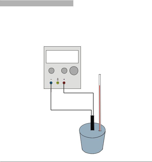
•Set up the circuitry according fig. 1.
•Switch on the power supply and adjust it to give a current of about 4 A. Switch the heater off.
1
•Before starting the experimental run, wait for a few minutes before taking the temperature of the calorimeter block.
•Switch on the heater and start the clock.
•Wait until the temperature has risen about 20oC and record the time and final temperature.
The specific heat capacity can then be calculated from the equation:
I U t = m c (θ2 −θ1 )
with I: current, U: voltage, t: time, m: mass of calorimeter block, c: specific heat capacity, θ1: initial temperature, θ2: final temperature
6.General notes
6.1Explanation of how to minimise the error
Assuming that the readings for the current and voltage are reasonable accurate, the two main sources of error in the experiment will be the readings of the temperature change and the effects of any heat loss.
Obviously the heat loss will depend on the excess temperature above the room temperature, so this can be minimised by keeping the temperature rise as small as possible.
If the thermometer can only be read accurately to 1o, then a temperature rise of 10o would give a 10% error, which is really too large for this type of experiment. Therefore, it is a balance between the error introduced by a large temperature increase causing heat losses, and a small temperature increase giving a large percentage error in the temperature readings. A 20o rise in temperature will give a 5% error in reading the thermometer (assuming it can only be read accurately to 1o) and a reasonable low error due to heat loss.
6.2 Rumford’s correction
Rumford argued that heat losses could be eliminated by the following process. If the metal block is kept in a fridge for several hours before the experiment, then it will start at, say, θ below room temperature. If its final temperature after the experiment was θ above room temperature, then the heat it took in while below room temperature would be equal to the heat it gave out while above room temperature, so there would be no heat loss.
U33020
4.00 12.0
A V
0...5 A |
0...20 V |
|
|
|
|
|
|
|
Fig. 1 Experimental set up
3B Scientific GmbH • Rudorffweg 8 • 21031 Hamburg • Germany • www.3bscientific.com Subject to technical amendment
© Copyright 2008 3B Scientific GmbH
 Loading...