


3B SCIENTIFIC® PHYSICS
Mikrovoltmeter U8530501
Bedienungsanleitung
02/08 SP
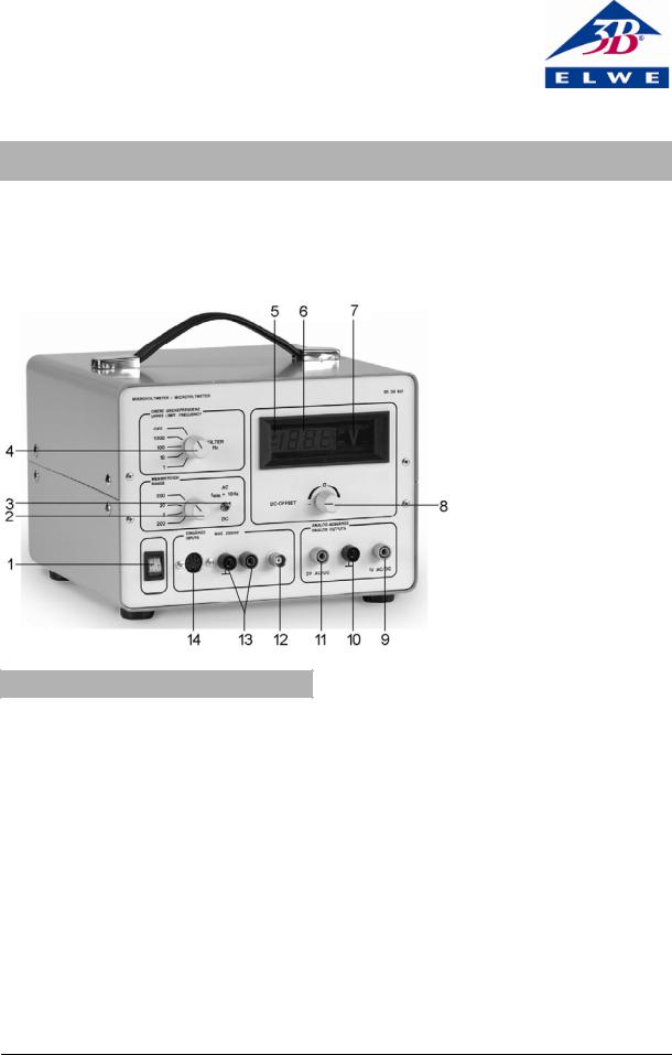
1 |
Netzschalter |
2 |
Messbereichswahl |
3 |
AC/ DC Umschalter |
4 |
Grenzfrequenzsteller |
5 |
Polaritätsanzeige |
6 |
Messwertanzeige |
7 |
Anzeige für Messeinheit |
8 |
DC-Offset |
9 |
AC/DC Ausgang 1 V |
10 |
Erdung / Masse |
11 |
AC/DC Ausgang 2 V |
12 |
Eingang BNC-Buchse |
13 |
Eingang 4-mm- |
|
Sicherheitsbuchsen |
14 |
Eingang 5-polige DIN-Buchse |
1. Sicherheitshinweise
Das Mikrovoltmeter entspricht den Sicherheitsbestimmungen für elektrische Mess-, Steuer-, Regelund Laborgeräte nach DIN EN 61010 Teil 1 und ist nach Schutzklasse I aufgebaut. Es ist für den Betrieb in trockenen Räumen vorgesehen, die für elektrische Betriebsmittel geeignet sind.
Bei bestimmungsgemäßem Gebrauch ist der sichere Betrieb des Gerätes gewährleistet. Die Sicherheit ist jedoch nicht garantiert, wenn das Gerät unsachgemäß bedient oder unachtsam behandelt wird.
Wenn anzunehmen ist, dass ein gefahrloser Betrieb nicht mehr möglich ist (z.B. bei sichtbaren Schäden), ist das Gerät unverzüglich außer Betrieb zu setzen.
In Schulen und Ausbildungseinrichtungen ist der Betrieb des Gerätes durch geschultes Personal verantwortlich zu überwachen.
•Vor Erstinbetriebnahme überprüfen, ob der auf der Gehäuserückseite aufgedruckte Wert für die Netzanschlussspannung mit dem ortsüblichen Wert übereinstimmt.
•Vor Inbetriebnahme das Gehäuse und die Netzleitung auf Beschädigungen untersuchen und bei Funktionsstörungen oder sichtbaren Schäden das Gerät außer Betrieb setzen und gegen unbeabsichtigten Betrieb sichern.
•Gerät nur an Steckdosen mit geerdetem Schutzleiter anschließen.
•Experimentierleitungen vor dem Anschluss auf schadhafte Isolation und blanke Drähte überprüfen.
•Gerät nur durch eine Elektrofachkraft öffnen lassen.
1

2. Beschreibung
Mit dem Gerät können extrem kleine Gleichund Wechselspannungen (max. 2 V), z.b. Thermo-, Induktionsund Photospannungen, gemessen und verstärkt werden. Die Anzeige erfolgt mit Hilfe eines LED-Displays. Zusätzlich kann ein Demonstrationsmessgerät angeschlossen werden. Das Messsignal wird über eine BNC-Buchse oder 4-mm- Sicherheitsbuchsen zugeführt. Ein Umschalter ermöglicht die Durchführung von ACbzw. DCMessungen.
In den Messeingang ist ein Filter zur Signalglättung oder oberen Begrenzung der Messfrequenz zuschaltbar. Es können 4 Festfrequenzen eingestellt werden. Der Filter ermöglicht die Verminderung von Störspannungen bei Gleichund Wechselspannungsmessungen. Eine zusätzliche DIN-Buchse ermöglicht einen einfachen Anschluss von Hallsonden.
Das Gerät U8530501-115 ist für eine Netzspannung von 115 V (±10 %) ausgelegt, U8530501-230 für 230 V (±10 %).
3. Technische Daten
Ausgangsspannung: |
0 – ±2 V |
Ausgangsstrom |
max. 1 mA |
Eingangswiderstand |
DC-Bereich: 100 kΩ |
|
AC-Bereich: 900 kΩ |
Messanzeige |
3,5-stellige LED-Anzeige |
Eingangsanschlüsse: |
zwei 4-mm- |
|
Sicherheitsbuchsen |
|
BNC-Buchse |
|
5-polige DIN-Buchse |
Ausgangsanschlüsse: |
drei 4-mm- |
|
Sicherheitsbuchsen |
Netzanschlussspannung: |
siehe Gehäuserückseite |
Primärsicherung: |
siehe Gehäuserückseite |
Abmessungen: |
235 x 250 x 180 mm³ |
Masse: |
ca. 3,3 kg |
4.Bedienung
4.1Betrieb als DC-Messgerät
•Betriebsspannung anlegen.
•Umschalter auf DC stellen.
•Messbereich einstellen (200 μV–200 mV).
•Eingang kurzschließen und mit DC-Offset Nullpunkt justieren.
•Kurzschluss entfernen und den Verbraucher an den Eingang anschließen.
4.2 Betrieb als AC-Messgerät
•Betriebsspannung anlegen.
•Umschalter auf AC stellen.
•Messbereich einstellen (200 μV–200 mV).
•Verbraucher an den Eingang anschließen.
4.3 Betrieb als DC-Messverstärker
•Betriebsspannung anlegen.
•Umschalter auf DC stellen.
•Messbereich einstellen (200 μV–200 mV).
•Eingang kurzschließen und mit DC-Offset Nullpunkt justieren.
•Kurzschluss entfernen und das Demonstrationsmessgerät (analoge Anzeige, Messbereich bis 2 V) an den Ausgang anschließen.
•Verbraucher an den Eingang anschließen.
4.4 Betrieb als AC-Messverstärker
•Betriebsspannung anlegen.
•Umschalter auf AC stellen.
•Messbereich einstellen (200 μV–200 mV).
•Demonstrationsmessgerät (Analoge Anzeige, Messbereich bis 2 V) an den Ausgang anschließen.
•Verbraucher an den Eingang anschließen.
Elwe Didactic GmbH • Steinfelsstr. 6 • 08248 Klingenthal • Deutschland • www.elwedidactic.com 3B Scientific GmbH • Rudorffweg 8 • 21031 Hamburg • Deutschland • www.3bscientific.com Technische Änderungen vorbehalten
© Copyright 2008 3B Scientific GmbH
3B SCIENTIFIC® PHYSICS
Microvoltmeter U8530501
Instruction sheet
02/08 SP
1 ON/OFF switch
2 Measuring range selector
3 AC/DC selector switch
4 Cut-off frequency regulator
5 Polarity display
6 Measured value display
7 Measuring unit display
8 DC offset
9 AC/DC output, 1 V
10 Earthing/ground
11 AC/DC output 2 V
12 Input BNC connector
13 Input 4-mm safety connector
14 Input 5-pin DIN connector
1. Safety instructions
The microvoltmeter conforms to all safety regulations for electrical measuring, control, monitoring and laboratory equipment, as specified under DIN EN 61010, Section 1, and the equipment has been designed to meet protection class I. It is intended for operation in a dry environment, suitable for the operation of electrical equipment and systems.
Safe operation of the equipment is guaranteed, provided it is used correctly. However, there is no guarantee of safety if the equipment is used in an improper or careless manner.
If it may be assumed for any reason that nonhazardous operation will not be possible (e.g. visible damage), the equipment should be switched off immediately and secured against any unintended use.
In schools and other educational institutions, the operation of the microvoltmeter unit must be su-
pervised by qualified personnel.
•Before using the microvoltmeter for the first time, confirm that the specifications printed on the rear side of the housing are compatible with the local mains voltage.
•Before using the microvoltmeter for the first time, check the housing and the mains lead for any damage. In the event of any malfunction/operational defect or visible damage, switch off the unit immediately and secure it against unintended use.
•The instrument may only be connected to the mains via a socket that has an earth connection.
•Before making any connections, check the experiment leads for damaged insulation and exposed wires.
•The equipment may only be opened/repaired by qualified and trained personnel.
1

2. Description
The microvoltmeter is used to measure and amplify extremely low AC/DC voltages (max. 2 V), e.g. thermo-electric voltages, induced voltages and photo-voltages. The values are indicated by an LED display. In addition, a large-format multimeter can be connected. The measured signal is conveyed via a BNC connector or 4-mm safety connectors. A selector switch makes it possible to carry out AC or DC measurements.
A filter for smoothing the signal or for fixing the upper limit of the measuring frequency can be connected to the measuring input. Four fixed frequencies can be set. The filter makes it possible to reduce noise voltage when conducting AC or DC voltage measurements. Thanks to an additional DIN connector, Hall probes can also be easily connected.
The apparatus U8530501 -115 is for operation with a mains voltage of 115 V (±10%), and the unit U8530501 -230 is for operation with a mains voltage of 230 V (±10%).
3. Technical data
Output voltage: |
0 to ±2 V |
Output current: |
max. 1 mA |
Input impedance: |
DC range: 100 kΩ |
|
AC range: 900 kΩ |
Display: |
3.5-figure value LED display |
Input connections: |
two 4-mm safety connectors |
|
BNC connector |
|
5-pin DIN connector |
Output connections: |
three 4-mm safety connec- |
|
tors |
Mains voltage: |
see rear of equipment hous- |
|
ing |
Primary fuse: |
see rear of equipment hous- |
|
ing |
Dimensions: |
235 mm x 250 mm x 180 mm |
Weight: |
3.3 kg approx. |
4.Operation
4.1Operation as a DC meter
•Turn on the mains voltage
•Set the selector switch to DC.
•Set the measuring range (200 μV-200 mV).
•Short the input and adjust the zero calibration with the DC offset knob.
•Remove the short and connect the load to the input.
4.2 Operation as an AC meter
•Turn on the mains voltage.
•Set the selector switch to AC.
•Set the measuring range (200 μV-200 mV).
•Connect the load to the input.
4.3 Operation as a DC instrumentation amplifier
•Turn on the mains voltage
•Set the selector switch to DC.
•Set the measuring range (200 μV-200 mV).
•Short the input and adjust the zero calibration with the DC offset knob.
•Remove the short and connect a demonstration multimeter (analog display, measuring range up to max. 2 V) to the output.
•Connect the load to the input.
4.4Operation as an AC instrumentation amplifier
•Turn on the mains voltage
•Set the selector switch to AC.
•Set the measuring range (200 μV-200 mV).
•Connect a demonstration multimeter (analog display, measuring range up to max. 2 V) to the output.
•Connect the consumer equipment to the input.
Elwe Didactic GmbH • Steinfelsstr. 6 • 08248 Klingenthal • Germany • www.elwedidactic.com 3B Scientific GmbH • Rudorffweg 8 • 21031 Hamburg • Germany • www.3bscientific.com Subject to technical amendments.
© Copyright 2008 3B Scientific GmbH
 Loading...